The AK-47 · Volume 23
The Retention Joint — Failure Modes, Hoop Stress and Groove Depth
This is the engineering volume. It works through what the barrel retention joint has to survive, how much of the barrel wall can be given up to it, and what depth and profile the analysis supports — with the arithmetic shown, because a safety factor without its inputs cannot be checked.
It also resolves the disagreement flagged at the end of Vol 22, and the resolution turns out to be the most useful thing in the volume.
23.1 The Joint, and Its Three Failure Modes
Two mechanisms hold the barrel. The interference fit carries the load in normal service through friction across the journal-to-bore interface. The cross-pin is a positive backstop for the case where the fit has fretted loose, the rifle has been dropped on the muzzle, or fouling and repeated firing have worked the joint.
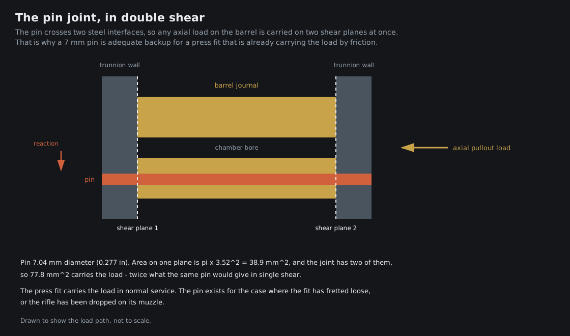
The pin works in double shear — it is supported in both trunnion walls, and any axial load on the barrel tries to cut it at both interfaces simultaneously. One plane through a 7.04 mm pin is π × 3.52² = 38.9 mm²; the joint has two of them, so 77.8 mm² carries the load. That is twice what the same pin gives in a single-shear joint, and it is why a pin this size is adequate for a backup role.
Three failure modes have to be designed against, and they are governed by different things:
Table 1 — Three failure modes have to be designed against, and they are governed by different things
| Failure mode | Where | Governed by |
|---|---|---|
| Pin shear | At each trunnion wall / journal interface | Pin section area × shear strength, doubled |
| Bearing | The groove walls in the journal | Pin diameter × groove depth × material yield |
| Burst or fatigue of the bore wall | The thin wall between the groove floor and the chamber bore | Lamé hoop stress, multiplied by the notch’s Kt, over cycles |
The first is comfortable. The interesting ones are the second and third, and they pull in opposite directions: bearing wants a deep groove, burst margin wants a shallow one.
23.2 First, Which Joint Is It?
The build’s two source documents describe two different joints. The build reference describes a hole drilled through the journal in place, with the pin passing through the barrel. The engineering analysis describes a groove cut across the journal surface, with the pin spanning it and never entering the barrel.
The geometry decides it, and the check takes four numbers.
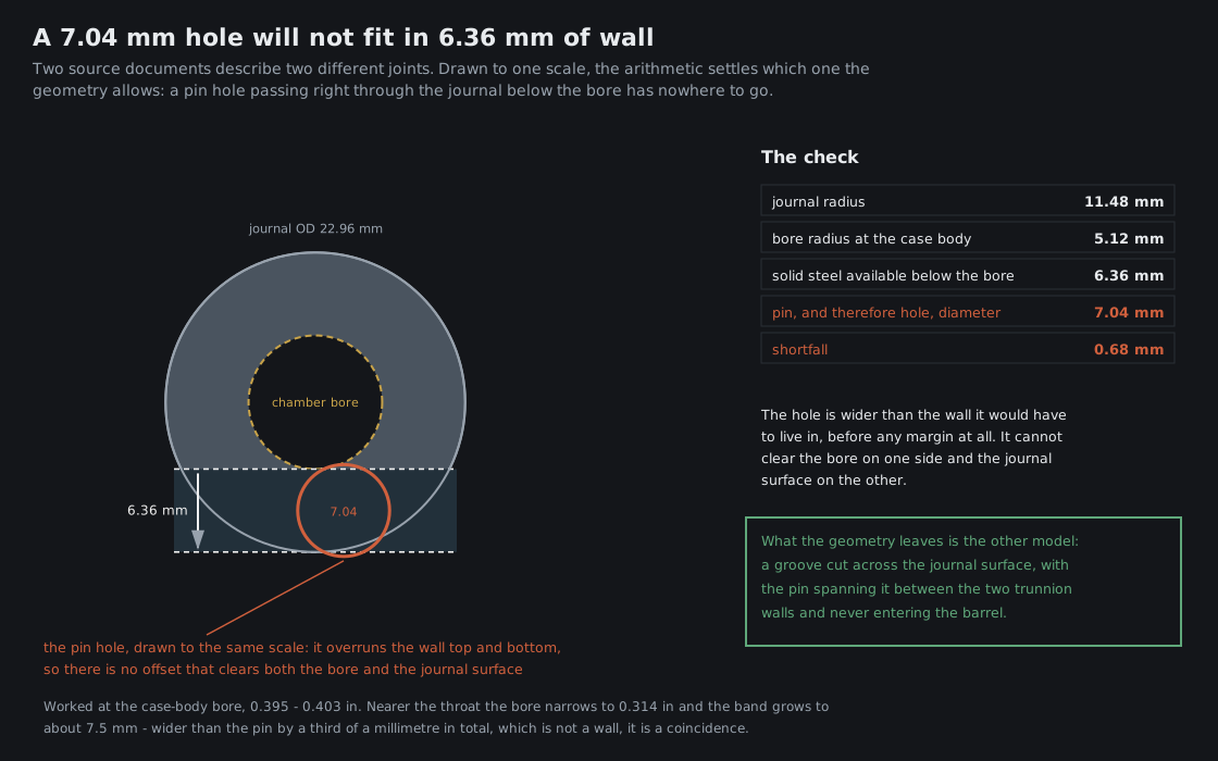
- Journal radius: 0.904 in / 2 = 0.452 in = 11.48 mm
- Chamber bore radius at the case body, the relevant inner surface where the pin would pass: 0.403 in / 2 = 0.2015 in = 5.12 mm
- Solid steel available below the bore: 11.48 − 5.12 = 6.36 mm
- Diameter of the hole a 7.04 mm pin needs: 7.04 mm
A 7.04 mm hole does not fit inside 6.36 mm of wall. It is 0.68 mm too wide before any margin at all, so there is no offset that clears the chamber bore on one side and the journal surface on the other. Further forward, where the bore has narrowed to 0.314 in, the band grows to about 7.5 mm — which exceeds the pin by about half a millimetre in total, a quarter of a millimetre a side, and that is not a wall.
So the through-hole model is not something to be argued about on engineering grounds; it is geometrically unavailable. The joint is a groove, which is also what factory practice on this pattern produces, and the rest of this volume analyses the groove.
Two caveats, stated plainly. The chamber bore figures come from a barrel drawing recorded in the build documentation and have not been confirmed on the specific barrel. And the finding is about the geometry, not about anyone’s competence — the two documents were written days apart, and the through-hole description reads as a reasonable inference about what drilling a virgin barrel would produce. The arithmetic is what settles it, which is exactly why it is written out here.
23.3 The Wall Budget
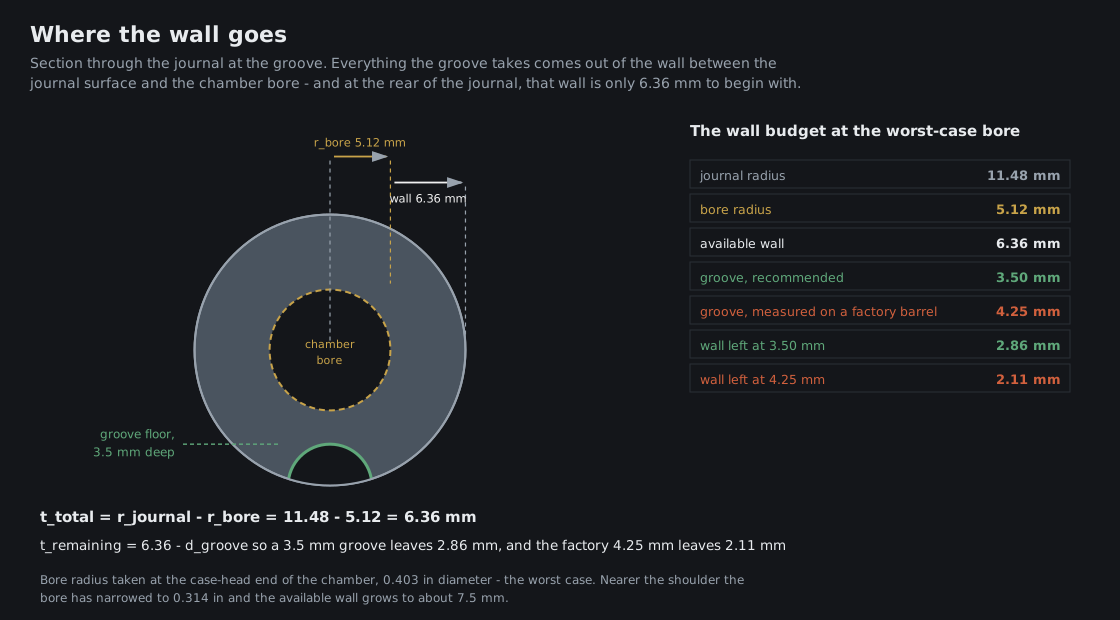
The constraint is the wall between the journal surface and the chamber bore at the groove’s axial position:
t_total = r_journal − r_bore = 11.48 − 5.12 = 6.36 mm
t_remaining = t_total − d_groove
The chamber bore is not one diameter. It steps down from the bolt face toward the muzzle, and which figure applies depends on where along the journal the groove sits:
Table 2 — The chamber bore is not one diameter. It steps down from the bolt face toward the muzzle, and which figure applies depends on where along the journal the groove sits
| Location in the chamber | Bore diameter | Bore radius | Wall available |
|---|---|---|---|
| Case head area | 0.403 in | 5.12 mm | 6.36 mm |
| Case body | 0.395 in | 5.02 mm | 6.46 mm |
| Case neck | 0.343 in | 4.36 mm | 7.12 mm |
| Throat / leade | 0.314 in | 3.99 mm | 7.49 mm |
| Rifled bore | 0.300 in | 3.81 mm | 7.67 mm |
Everything below uses the 0.403 in figure — the worst case, a groove toward the bolt-face end of the journal. A groove nearer the shoulder has more than a millimetre of extra wall to work with.
One error worth naming, because the build’s own analysis flags it against an earlier draft of itself: the rifled-bore diameter must not be used for this calculation. The barrel drawing’s section showing 0.300 in land-to-land and 0.310 in groove-to-groove applies forward of the chamber, not at the journal. Using 7.62 mm as the inner diameter at the groove overstates the available wall by more than 2 mm and is non-conservative in the direction that matters.
23.4 Hoop Stress: Lamé, Worked
Under chamber pressure the bore wall carries circumferential stress, maximum at the inner surface. The wall-to-radius ratio here is 6.36 / 11.48 = 0.55, far past the 0.1 threshold where thin-wall approximations apply, so the thick-wall solution is required:
σθ = P (ri² + ro²) / (ro² − ri²)
with P the internal pressure, ri the bore radius, and ro the outer radius — which the groove reduces to (r_journal − d_groove).
The design pressure used is 379 MPa (55,000 psi). That is deliberately above both published maxima: CIP’s for 7.62×39 is 355.0 MPa (51,490 psi) and SAAMI’s is 310.3 MPa (45,010 psi). The 379 MPa figure sits about 7 per cent above CIP, covering peak transients, ammunition variation and proof conditions, so every safety factor below is conservative against the published standards.
Worked at zero groove depth:
σθ = 379 × (5.12² + 11.48²) / (11.48² − 5.12²) = 379 × (26.2 + 131.8) / (131.8 − 26.2) = 379 × 158.0 / 105.6 = 379 × 1.497 = 567 MPa
Against a 4150V yield taken at 965 MPa, that is a safety factor of 1.70 before any groove is cut. For comparison, the thin-wall approximation σ = P r / t would give 379 × 5.12 / 6.36 = 305 MPa — about half the real figure, which is why it must not be used here.
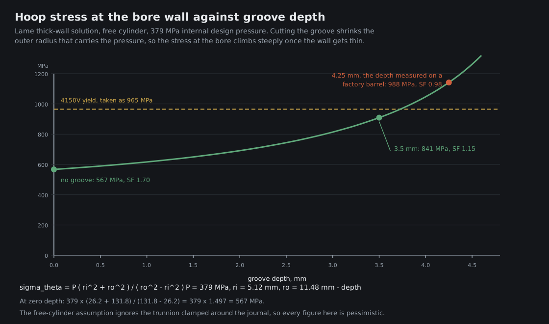
Table 3 — Hoop Stress: Lamé, Worked
| Groove depth | ro (mm) | Wall left | σθ | SF vs 965 MPa |
|---|---|---|---|---|
| 0 mm | 11.48 | 6.36 mm | 567 MPa | 1.70 |
| 2.0 mm | 9.48 | 4.36 mm | 680 MPa | 1.42 |
| 2.5 mm | 8.98 | 3.86 mm | 721 MPa | 1.34 |
| 3.0 mm | 8.48 | 3.36 mm | 774 MPa | 1.25 |
| 3.5 mm | 7.98 | 2.86 mm | 841 MPa | 1.15 |
| 4.0 mm | 7.48 | 2.36 mm | 930 MPa | 1.04 |
| 4.25 mm | 7.23 | 2.11 mm | 988 MPa | 0.98 |
| 4.5 mm | 6.98 | 1.86 mm | 1,057 MPa | 0.91 |
The steel figure deserves its own line. 4150 in the quenched-and-tempered condition is quoted at 1,100–1,300 MPa tensile with yield at or above 900 MPa; the 965 MPa used here is a conservative working value within that band, and 4150 is the alloy class accepted for US military barrel specification. The “V” denotes a vanadium addition for toughness.
23.5 Why the Factory Groove Is Deeper Than the Analysis Recommends
The groove measured on a factory barrel is about 4.25 mm, which the table puts at a free-cylinder safety factor of 0.98 — below yield-equivalent. Factory barrels do not fail at the groove, so the model is missing something, and it is worth saying what rather than treating the discrepancy as noise.
The Lamé calculation above assumes a free cylinder: a barrel with nothing around it. The journal is not free. It is enclosed in the trunnion bore under an interference fit, which is a compound-cylinder arrangement — the outer cylinder restrains the radial expansion of the inner one, and the barrel transmits part of the pressure load into the trunnion instead of carrying all of it alone. Actual stress at the groove is therefore lower, and by an amount this analysis does not quantify. Add that the groove is narrow, so the weakening is local rather than a reduction in section along the barrel, and that real barrel steel exceeds the conservative 965 MPa figure.
The correct reading is not that the table is wrong but that it is pessimistic by a margin that has not been calculated. A recommendation of 3.5 mm therefore buys margin against a model that is already conservative — which is the right posture for a one-off build with no proof-testing programme behind it.
23.6 Bearing, and a Second Inconsistency
When axial load tries to push the barrel out, the groove wall bears against the pin:
σb = F / (d_pin × d_groove)
The design load is 5,000 lbf (22,250 N) — deliberately pessimistic, representing the press fit having gone loose. At 3.5 mm depth the bearing area is 7.04 × 3.5 = 24.6 mm², so:
σb = 22,250 / 24.6 = 904 MPa
The build’s analysis tabulates that figure against a 620 MPa generic-steel yield, giving a safety factor of 0.68, and then notes in its own commentary that the barrel is hardened and the real figure should be 965 MPa — which turns 0.68 into about 1.06. The table and the note disagree, and the note is right. Anyone reading the table alone would conclude that every groove depth up to 5 mm crushes, which is not what the analysis actually concludes.
A second point where the source over-credits the joint: it states that total bearing capacity is twice the per-side figure because there are two groove walls. For a load in one direction only one wall bears — the other resists the opposite direction. The doubling is available to the pin in double shear, which genuinely is two planes under one load, but not to the groove walls.
Neither correction changes the recommendation. Both change what the margin actually is, which is the point of writing them down.
23.7 Profile: Where the Fatigue Life Is
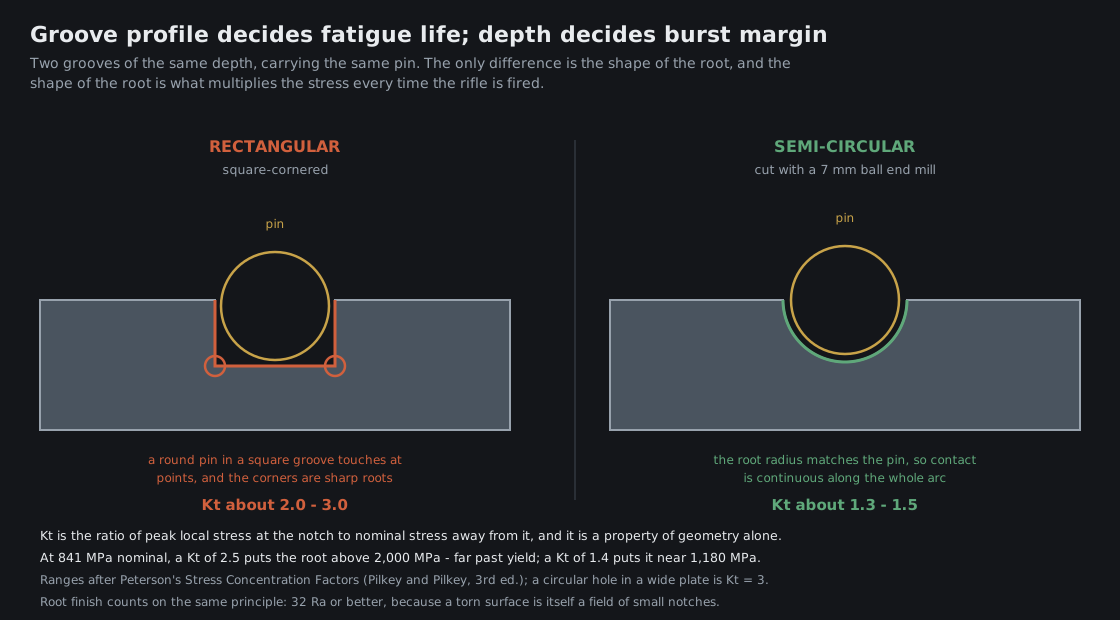
Depth sets the burst margin. Profile sets the fatigue life, and it is the larger effect.
A notch concentrates stress by a factor Kt, the ratio of peak local stress at the notch to nominal stress away from it. Kt is a property of geometry alone — not of the material, not of the load. A square-cornered groove presents a sharp re-entrant root and runs Kt ≈ 2.0–3.0. A semi-circular groove whose radius matches the pin’s runs Kt ≈ 1.3–1.5, because the transition is a smooth radius and the pin’s contact is conformal along the whole arc rather than at two points.
At 841 MPa nominal, the difference is between about 1,180 MPa at the root and something over 2,000 MPa. Fatigue cracks initiate at the worst stress raiser present, every time. That is why the profile outranks a few tenths of a millimetre of depth, and why the surface finish at the root — 32 Ra or better — belongs in the specification: a torn surface is itself a field of small notches.
23.8 Where the Two Curves Cross
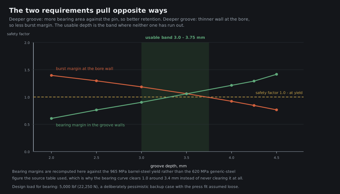
Plotting both requirements against depth — bearing recomputed against the 965 MPa barrel-steel yield rather than the generic figure — gives a usable band of roughly 3.0 to 3.75 mm, and a recommendation of 3.5 mm.
The full cutting specification that follows from all of the above:
Table 4 — The full cutting specification that follows from all of the above
| Parameter | Value | Why |
|---|---|---|
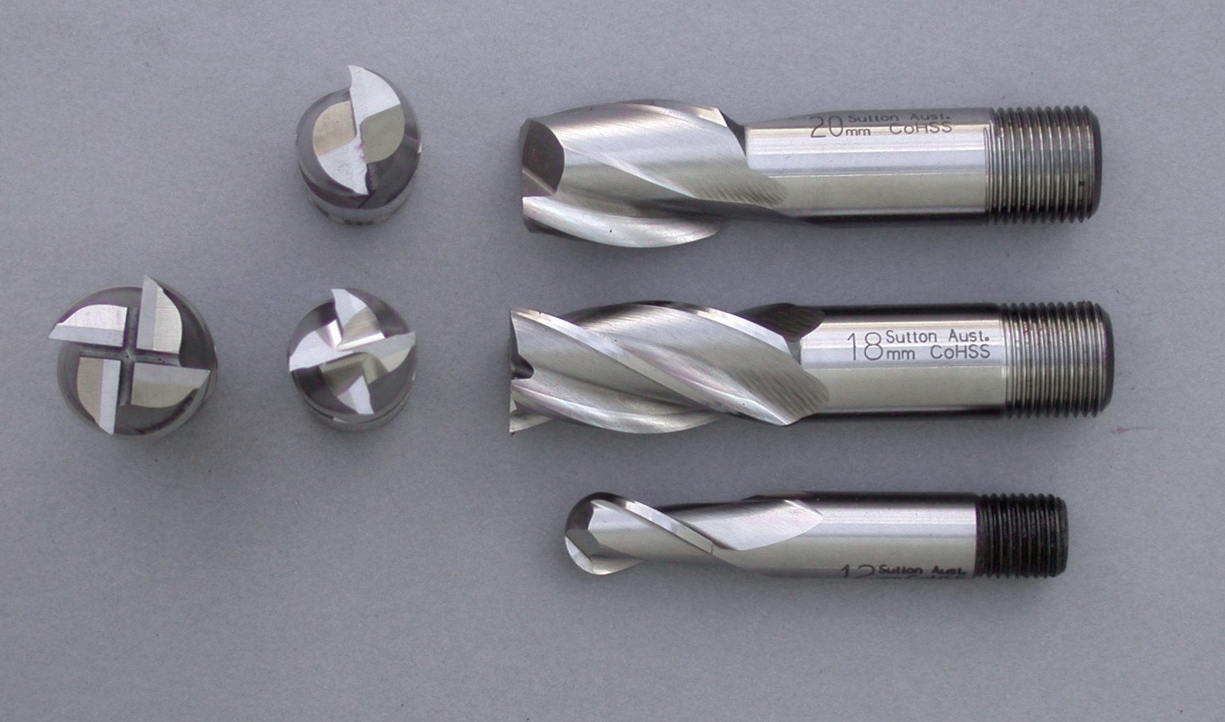
| Cutter | 7 mm carbide ball end mill | Root radius equal to pin radius; minimum Kt |
| Depth at centre | 3.5 mm | Both margins satisfied; 2.86 mm wall left at the worst-case bore |
| Width, axial | 7.0 mm, equal to pin diameter | Pin seats without axial slop |
| Root finish | 32 Ra (0.8 µm) maximum | Fatigue notch sensitivity |
| Spindle speed | 1,200–1,800 rpm hardened (28–34 HRC); 1,600–2,200 rpm annealed | 80–130 SFM for carbide in alloy steel; see Vol 19 |
| Depth of cut | 0.5 mm maximum per pass at the root | Light passes, flood coolant or cutting oil |
| Position | Confirmed clear of the bore, with at least one pin radius of clearance | The failure is not recoverable |
23.9 What This Analysis Does Not Establish
Three things, stated so that nothing here is read as more settled than it is.
The bore diameter at the groove’s actual position has not been measured on this barrel. Every figure above uses drawing values and the worst-case chamber station.
The groove’s axial position has not been fixed. It changes which bore diameter applies, and between the worst and best stations the available wall differs by more than a millimetre.
The free-cylinder model is conservative by an unquantified amount. Quantifying the trunnion’s containment would require a compound-cylinder analysis that has not been done, and doing it would move every safety factor above upward, not downward.
Vol 24 gathers these together with everything else that is still open.
Sources
- The builder’s engineering analysis of the retention joint for this rifle: dimensions, Lamé treatment, bearing table, Kt discussion, cutting parameters — with the internal inconsistencies noted above identified in this dive.
- The builder’s build reference for the same rifle, which describes the alternative through-hole joint.
- 7.62×39 pressure standards: CIP 355.0 MPa; SAAMI 310.3 MPa.
- 4150 / 41xx steel properties, quenched and tempered: 1,100–1,300 MPa tensile, yield at or above 900 MPa.
- Stress concentration factors after Peterson’s Stress Concentration Factors (Pilkey and Pilkey, 3rd ed.); thick-wall cylinder solution after standard elasticity texts.
Comments (0)