The AK-47 · Volume 21
Barrel Buildup Order — Four Components, One Possible Sequence
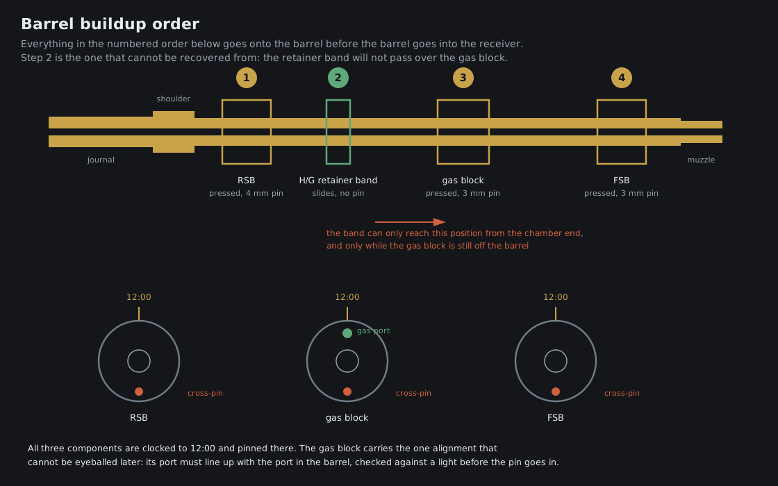
Four things go onto the barrel before it goes into the receiver: the rear sight base, the handguard retainer band, the gas block, and the front sight base. Three of them are pressed on and pinned. One slides. The order in which they go on is fixed by the geometry of the parts themselves, and getting it wrong means pressing a pinned component back off a barrel — which is recoverable — or discovering that a part cannot be installed at all without dismantling work that is already done.
21.1 The Order
Table 1 — The Order
| Step | Component | Retention | Clocking |
|---|---|---|---|
| 1 | Rear sight base | Pressed, 4 mm cross-pin, 5/32 in pilot | 12 o’clock |
| 2 | Handguard retainer band | Slides; no pin | Positioned, not clocked |
| 3 | Gas block | Pressed, 3 mm cross-pin, 1/8 in pilot | Gas port at 12 o’clock |
| 4 | Front sight base | Pressed, 3 mm cross-pin, 1/8 in pilot | Sight post at 12 o’clock |
| 5 | The populated barrel goes into the receiver | Interference fit | See Vol 22 |
21.2 Why the Order Is Not Optional
The retainer band is trapped by the gas block. This is the constraint that fixes everything else. The band is a plain ring that slides onto the barrel from the chamber end and takes up position behind the gas block. It has no pin and no fastener. It also has a smaller bore than the gas block’s outside profile, so once the gas block is pressed on and pinned, the band cannot pass it in either direction. If it was not fitted before step 3, the only route to fitting it is to drive out the gas block pin and press the gas block off a barrel it was interference-fitted onto — an operation that does no good to either part.
The receiver is in the way afterwards. Once the barrel is pressed into the receiver, the chamber end of the barrel is inside a steel box. Anything that has to slide on from that end cannot, and anything that has to be pressed on requires a press setup that now includes a receiver in the load path.
Pinning means drilling, and drilling means a vise. Each pressed component is cross-drilled and pinned. Doing that on a bare barrel is a straightforward vise-and-drill-press job. Doing it on an assembled rifle means fixturing the whole rifle to drill a 3 mm hole, with the receiver hanging off the end of the work.
Press force has to go somewhere. Pressing a component onto the barrel puts the reaction into the barrel. Pressing it onto a barrel that is already in a receiver puts the reaction into the receiver and, ultimately, into the interference fit and the headspace that Vol 20 established. The build order keeps every component press off the assembled rifle for exactly that reason.
21.3 Clocking, and the One Alignment That Cannot Be Fixed Later
All three pressed components sit at 12 o’clock — rear sight base, gas block, front sight base — and each is pinned there. Two of those three are sighting components, and a visibly canted front sight base is an annoyance that can be argued with later.
The gas block is different, because its alignment is functional rather than cosmetic: the port in the gas block must line up with the port drilled through the barrel wall. The check recorded in the build documentation is simple and should be done before the pin goes anywhere near the part: look through the gas block’s port with a light behind it, and confirm daylight through the barrel’s port. A gas block rotated a few degrees off, or set a few thousandths of an inch fore or aft of the barrel port, restricts the gas path. The rifle then short-strokes — it fails to cycle fully, fails to feed reliably, and the fault presents as a mysterious ammunition or magazine problem rather than as what it is.
The same alignment, once pinned wrong, has to be un-pinned and re-pressed to correct, and the pin hole drilled for the first attempt is still in the barrel.
21.4 Inspection Before the Press-In
The build documentation records a specific check at the end of the buildup, and it reads as a list of the things that are painful to discover later:
- All three cross-pins flush with, or just below, their surfaces.
- Rear sight base, gas block and front sight base all at 12 o’clock.
- The gas port clear and unobstructed, verified by light.
- No component able to rotate or rock on the barrel.
- The retainer band present, sliding freely, and able to reach its position behind the gas block.
That last item is worth one deliberate look, because the band is the part with no fastener holding it anywhere, and it is the easiest of the five to have simply forgotten.
21.5 What This Volume Hands to the Next One
At the end of the buildup the barrel is a populated assembly with three pinned components and one sliding band, and it has never been near the receiver. Vol 22 takes it from there: the interference fit, the incremental press, the headspace iteration from Vol 20, and then the operation that has no second attempt — establishing both axes of a cross-pin hole on a mill, in a rifle where neither the receiver nor the barrel has an existing hole to work from.
Sources
- The builder’s project notes and build reference for this rifle: buildup order, pin sizes and pilot drills, clocking requirements, gas port light check, pre-press inspection list.
Comments (0)