The AK-47 · Volume 19
Tooling and Setup — What the Operations Actually Require
There are exactly four machining operations in this build, and every one of them is a hole. Three of them are small pilot holes for component retention pins, drilled in a barrel held in a vise. The fourth is the barrel cross-pin hole, drilled through an assembled and headspaced rifle, and it is the one that dictates the tooling list. Vol 22 covers that operation; this volume covers what it takes to do it, and what the source material records about cutters and speeds.
19.1 Machine Tools
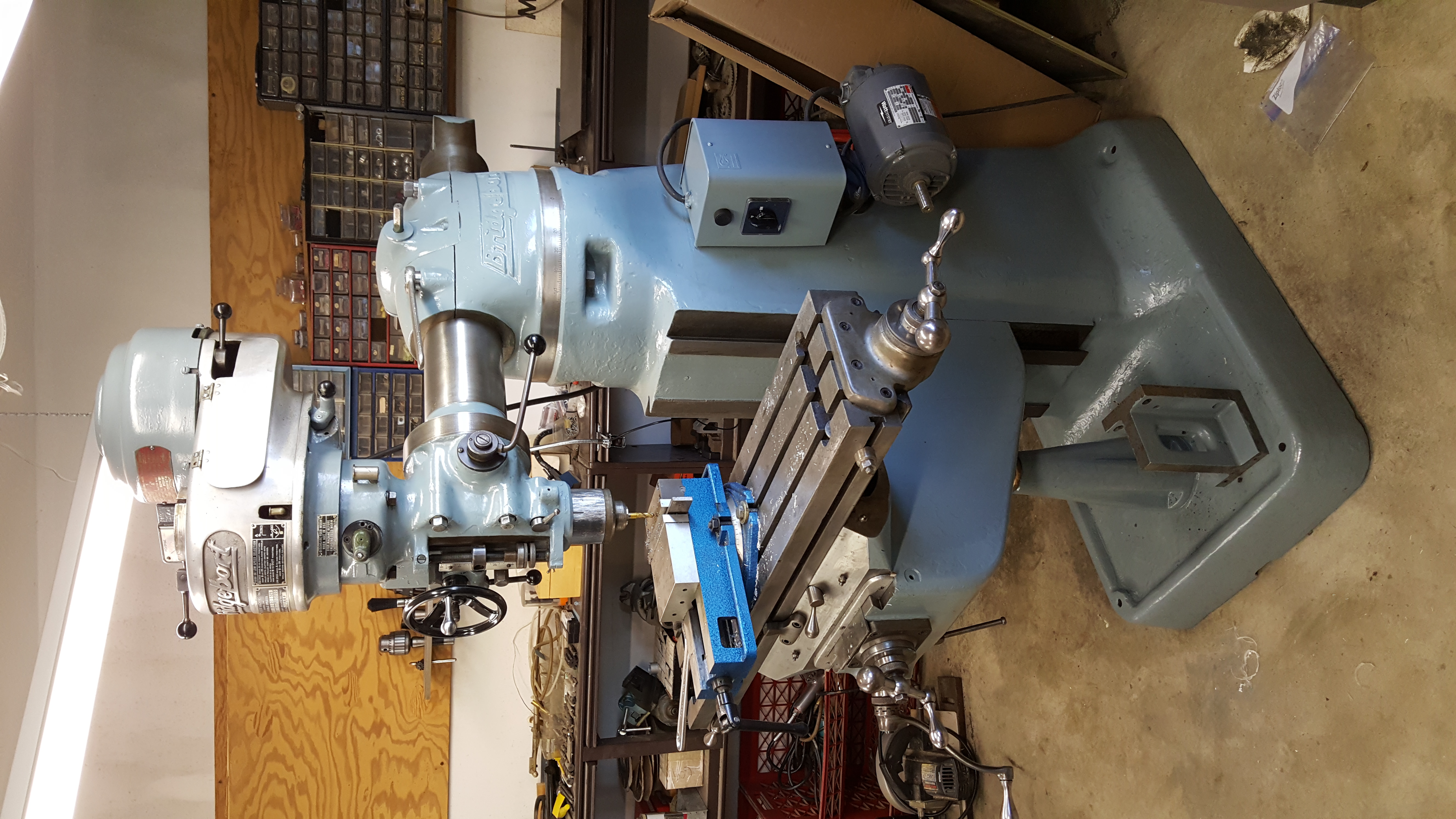
A milling machine with a vise, and a readout. The requirement is not metal removal — the total is a few cubic centimetres — but the ability to establish a zero on a reference surface, move a known distance from it, and come back to that position after changing cutters three times. A digital readout is doing the important work here; the alternative is counting handwheel graduations and backlash through three tool changes, on an operation that cannot be repeated.
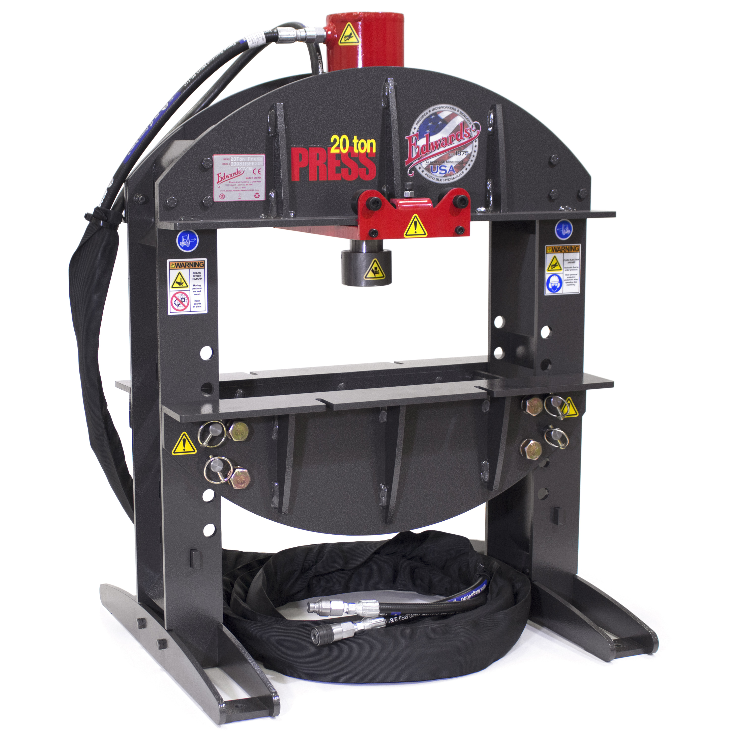
A hydraulic press. Used four times: the rear sight base, the gas block and the front sight base onto the barrel, and then the barrel into the receiver. The last of those is the one that needs real, controllable force, applied in small increments. A press is also what installs the finished cross-pin. Nothing in this build is hammered.
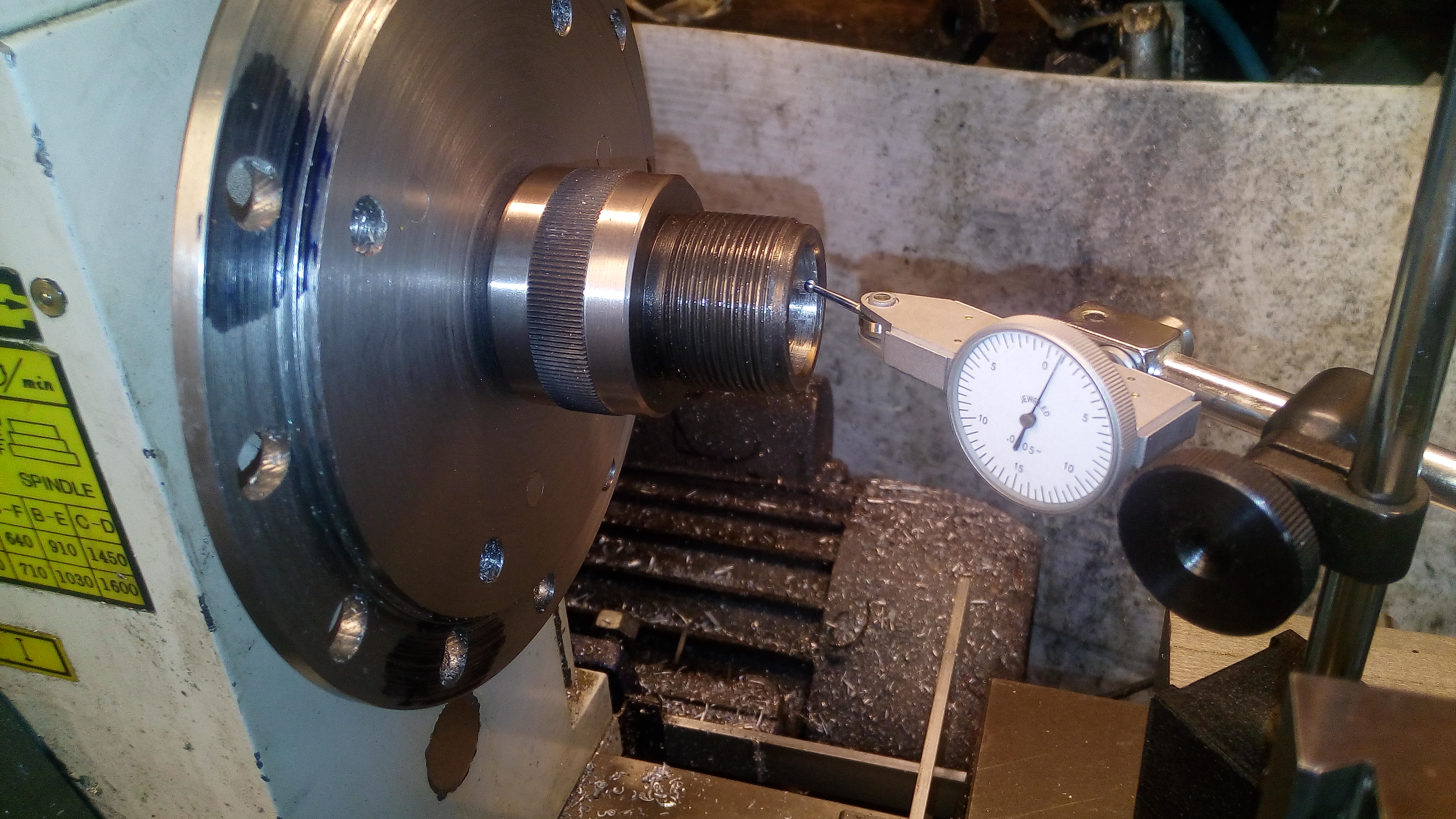
An edge finder or coaxial indicator, and a dial test indicator. The edge finder establishes the Y-axis reference from the receiver walls. The DTI confirms that the barrel axis is parallel to the table before anything is drilled — if the work is cocked in the vise, the hole through the far wall will not be coaxial with the hole through the near one, and the pin will not go through.
19.2 Measuring and Gauging
Table 1 — Measuring and Gauging
| Instrument | What it is for |
|---|---|
| CIP-spec GO and NO-GO gauges, 7.62×39 | The headspace decision — Vol 20 |
| Outside micrometer | Barrel journal OD, and the cross-pin OD |
| Bore or ID gauge | Trunnion bore ID, to confirm the interference before pressing |
| Depth micrometer | Journal shoulder position through the front of the receiver, for the X axis |
| Pin gauges | Checking the finished reamed hole: 7.0 mm passes, 0.278 in does not |
| Digital calipers | General work |
| Layout dye and a scribe, centre punch | Marking both receiver walls before the spindle turns |
The pin-gauge check deserves a note, because it is the only direct verification that the hole is right before an interference-fit pin is pressed into it. A 7.0 mm pin gauge entering freely and a 0.278 in (7.06 mm) gauge refusing to enter brackets the hole at or just under the 7.04 mm pin diameter, which is the interference the joint is designed around.
19.3 Cutting Tools, and the Sequence
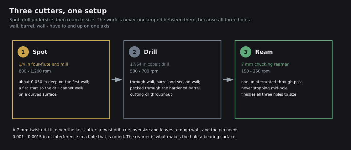
The cross-pin hole is made by three tools in succession, and the sequence recorded in the build documentation is specific about which tool does what:
Table 2 — The cross-pin hole is made by three tools in succession, and the sequence recorded in the build documentation is specific about which tool does what
| Step | Tool | Spindle speed | Purpose |
|---|---|---|---|
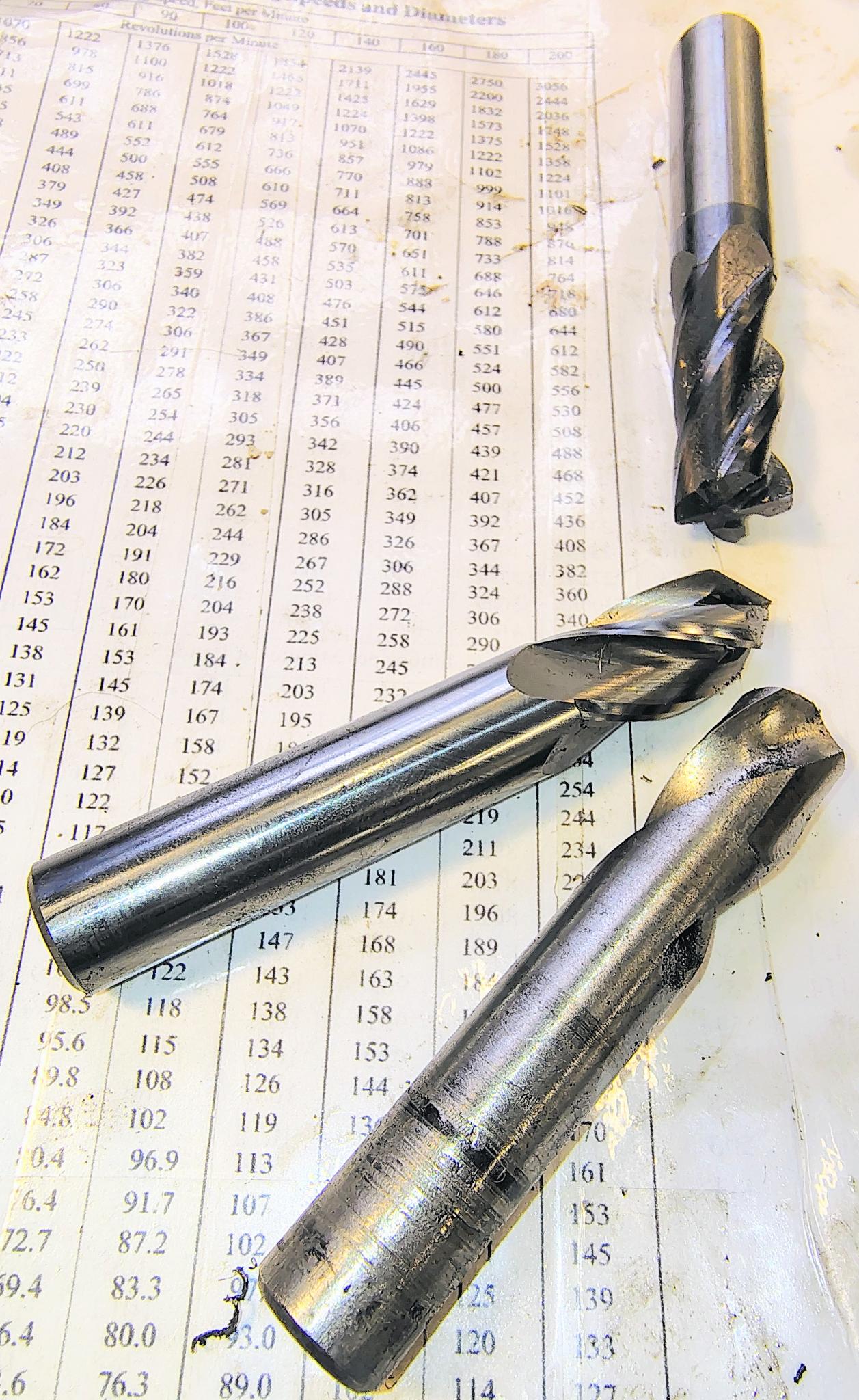
| Spot | 1/4 in four-flute end mill | 800 – 1,200 rpm | A flat, centred start about 0.050 in deep on the first wall |
| Drill | 17/64 in cobalt drill | 500 – 700 rpm | Through the near wall, the barrel, and the far wall |
| Ream | 7 mm chucking reamer | 150 – 250 rpm | All three holes to final size in one pass |
The end mill exists because the receiver wall is not flat where the hole goes. A twist drill started on a curved or cast surface walks, and a hole that walks on this operation cannot be recovered. An end mill cuts a flat pad and leaves the drill a centred start.
A 7 mm twist drill is never the finishing tool. A twist drill cuts oversize — how much depends on the drill, the setup and the operator, which is the problem — and leaves a torn wall. The joint needs 0.001 to 0.0015 in of interference in a round hole, and that tolerance is smaller than the error a twist drill introduces. The 17/64 in (6.75 mm) cobalt drill is deliberately undersize, leaving about a quarter of a millimetre on the diameter for the reamer to take out.
The reamer runs slowly and does not stop. Stopping a reamer in the hole leaves a witness ring at the point it stopped; backing it out under power tears the surface it just made. One continuous pass, generous cutting oil, light steady feed.
The three component retention pins are simpler work: a 5/32 in pilot for the 4 mm rear-sight-base pin, and a 1/8 in pilot for each of the 3 mm gas block and front sight base pins. Vol 21 covers where they go and in what order.
19.4 Speeds, and a Correction the Source Material Made to Itself
Spindle speeds for this material follow the standard surface-speed relation:
rpm = (SFM × 3.82) / D, with D in inches
For carbide in alloy steel of this class the working range is 80 to 130 surface feet per minute. At 100 SFM with a 7 mm (0.276 in) cutter:
rpm = (100 × 3.82) / 0.276 = 1,384 rpm
This figure matters for Vol 23, where a 7 mm ball end mill is the proposed cutter for the retention groove. It is worth recording that the build’s own engineering document originally specified 1,800 to 2,400 rpm for that cutter, and a later verification pass corrected it downward to 1,200–1,800 rpm for hardened barrel steel at 28–34 HRC and 1,600–2,200 rpm for annealed or normalised stock. The original figure was above the band the surface-speed arithmetic supports for hardened material. The corrected figures are the ones used in these volumes, and the correction is noted rather than quietly absorbed, because it is the kind of number that gets copied from a document into a control without being checked.
Note also that the reamer’s 150–250 rpm is not a slower version of the same calculation. Reaming is a sizing operation with many cutting edges taking a very small chip; it runs at roughly a third to a half of the equivalent drilling speed regardless of what the surface-speed formula suggests for its diameter.
19.5 Press Tooling and Consumables
The press needs three things made or bought before the barrel goes anywhere near it:
- A sleeve that contacts the barrel shoulder only. Never the threads, never the gas block, never the front sight base. Press force applied to a pinned component drives it off its pin.
- A fixture that holds the receiver square to the ram, with the trunnion bore on the press axis. A receiver pressed crooked galls the journal into the bore, and then neither part is usable.
- A barrel back-out tool. It threads into the muzzle and pulls the barrel back out of the receiver, and it is needed if the barrel is pressed in too far — which is a live possibility, because Vol 20’s procedure is deliberately a converging one. Commercial tooling exists for this pattern; the documented shop-made version is a half-inch bolt with a brass nut, the brass being there so that nothing harder than the chamber touches the chamber.
Consumables are unremarkable and non-negotiable: cutting oil for every drilling and reaming operation, light machine oil on the journal and bore for the press, layout dye, and compressed air and rags for chips. On the cross-pin operation, chips are cut inside an assembled rifle; they come out before anything else happens.
Sources
- The builder’s build reference for this rifle: tool list, cutter sequence, spindle speeds, press tooling, gauging.
- The builder’s engineering analysis for the retention groove, and its own later verification pass, for the ball end mill speeds and the correction recorded above.
- Standard surface-speed relation rpm = (SFM × 3.82) / D, as given in Machinery’s Handbook.
Comments (0)