The AK-47 · Volume 22
Pressing the Barrel, and Finding a Pin Hole That Does Not Exist Yet
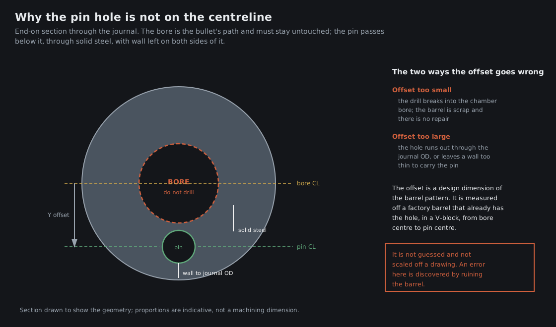
This is the hardest operation in the build and the only irreversible one. Everything before it can be undone: a component pressed onto the barrel can be pressed off, a barrel pressed too far into a receiver can be drawn back out. The cross-pin hole cannot be un-drilled, and it is cut into a rifle that is by then assembled, headspaced and finished.
It is also harder on this build than on most, because of a condition stated in Vol 18 and worth repeating: neither part has an existing hole. The barrel is virgin, with no cross-hole and no factory engagement feature. The milled receiver’s trunnion walls are solid. On a rebuild of a used rifle, the factory holes in the trunnion give the position; here, both axes have to be established by measurement, on the mill, after headspace is set.
22.1 The Interference Fit
The barrel is held in the receiver by friction across the journal-to-bore interface, and the amount of friction is set by the interference: 0.0005 to 0.001 in, with the journal that much larger than the trunnion bore. On a journal of about 23 mm diameter and 42.65 mm length, that is the whole primary retention of the barrel in the rifle.
Both parts are measured before anything is pressed — journal OD with an outside micrometer, trunnion bore ID with a bore gauge — because the interference is the difference between two measurements and neither is worth assuming. Too little and the barrel is loose in a joint that is meant to be a friction joint. Too much and the journal galls into the bore on the way in, which ruins both parts at once and is not recoverable by pressing harder.
The press-in itself follows Vol 20’s convergent procedure: receiver square in a fixture, a sleeve bearing on the barrel shoulder only, small increments of about 0.100 in, and a headspace check between increments. The first movement takes the most force, as the interference engages. A force that spikes sharply mid-press is an alignment problem, not a reason for more pressure.
22.2 Finding the Y Axis: The Bore Centreline Is a Reference, Not a Target
The pin passes below the bore, through solid steel. The bore centreline is found because it is the only precise, symmetric reference the geometry offers, and the drill position is then a known offset from it.
The sequence recorded in the build documentation:
- Edge-find the top receiver wall surface; zero the readout’s Y axis on it.
- Edge-find the bottom receiver wall surface; read the Y value.
- Halve it, and move the spindle there. That position is the bore centreline. Zero Y here — and do not drill here.
- Move down, on the negative Y axis, by the offset for this barrel pattern.
Step 4 is where the build stops, and it is worth being blunt about why. The offset from bore centre to pin centre is a design dimension of the barrel, and it cannot be derived from the receiver or calculated from first principles. It has to be measured off a factory barrel of the same pattern that already has its hole: the barrel goes in a V-block, the bore centre is found with a coaxial indicator, and the distance from bore centre to pin-hole centre is measured directly. Builder discussion and factory drawings can corroborate a figure; neither substitutes for measuring one.
The two failure modes are both terminal and both immediate. Too little offset and the drill breaks into the chamber bore. Too much, and the hole runs out through the journal surface or leaves a wall too thin to carry a pressed pin. In both cases the barrel is finished, and the fault is discovered by producing it.
22.3 Finding the X Axis: Where Along the Journal
The X position is less fraught, because it has tolerance. The pin must land within the journal — the reduced-diameter section inside the trunnion bore — and not on the shoulder step or off the end of the journal. The documented method:
- Reach through the front of the receiver with a depth micrometer and locate the journal shoulder, recording its distance from the receiver’s front face.
- Subtract about 21 mm, half of the 42.65 mm journal length, to reach the journal’s middle.
- Move the spindle there and note the X reading.
Anything within the central half of the journal length is acceptable. What is not available is a fixed dimension from the receiver face: the journal is wherever headspace put it, so a different amount of pressing means a different X. This is the mechanical expression of Vol 20’s rule that headspace is set first.
Then layout dye on both receiver walls, both axes scribed, the intersection centre-punched on each wall, and a deliberate look at which quadrant the punch marks are in before the spindle turns.
22.4 Drilling
The cutter sequence and speeds are in Vol 19. Three points belong here:
One setup, no re-clamping. The near wall, the barrel and the far wall are cut in one operation without moving the work. The three holes have to be coaxial, and re-clamping between operations does not reproduce a position to the tolerance a pressed pin needs.
The barrel is hardened. The cobalt drill pecks through it, with cutting oil throughout, and the readout position stays locked.
The verification is by pin gauge. After reaming and deburring: 7.0 mm should pass freely, 0.278 in should not. That brackets the finished hole against the 7.04 mm pin.
22.5 The Pin
The pin for this pattern is 0.277 in (7.04 mm) in diameter and 1.435 in (36.45 mm) long. It is not the AKM’s 0.278 in pin, and the distinction is not pedantry: the joint’s whole interference is 0.001 to 0.0015 in in a 7.00 mm reamed hole, so a thousandth of an inch is most of it. Too small a pin is a slip fit in a joint that must not slip. Too large is a split trunnion wall.
An oversize 0.302 in pin is available for the case where a hole has been cut oversize, which is the one recovery path this operation has.
Installation is by press, never by hammer. A hammered pin goes in at an angle, galls the hole it is meant to bear in, and can crack a wall. The pin should start by hand and refuse to go further by hand — if it slides in, the interference is not there and an oversize pin is the answer.
Then the last step, which is not optional: headspace is verified again, GO and NO-GO, on the finished rifle.
22.6 The Question This Volume Cannot Settle
The build documentation describes the drill passing through the near wall, through the barrel journal, and out through the far wall — creating the barrel’s engagement hole in place, in an assembled and headspaced rifle. The companion engineering analysis for the same build describes a different joint: a groove cut across the journal’s outer surface, spanned by a pin that passes through both trunnion walls and never enters the barrel.
These are not two descriptions of one thing. They are two different joints, with different failure modes and different consequences for the wall between the pin and the chamber.
Vol 23 works the geometry and finds that it settles the question, because a 7.04 mm hole and the available wall are not compatible numbers. Until that is resolved against the actual barrel — and until the bore-centre-to-pin-centre offset has been measured on a factory barrel — the operation in this volume is documented, not performed. That is the state of the build recorded in Vol 24.
Sources
- The builder’s project notes and build reference for this rifle: interference band, press procedure, Y and X axis location methods, drilling sequence, pin specification and installation.
- The builder’s engineering analysis for the same build, which describes the alternative joint discussed above and is taken up in Vol 23.
Comments (0)