The SKS · Volume 9
How It Works
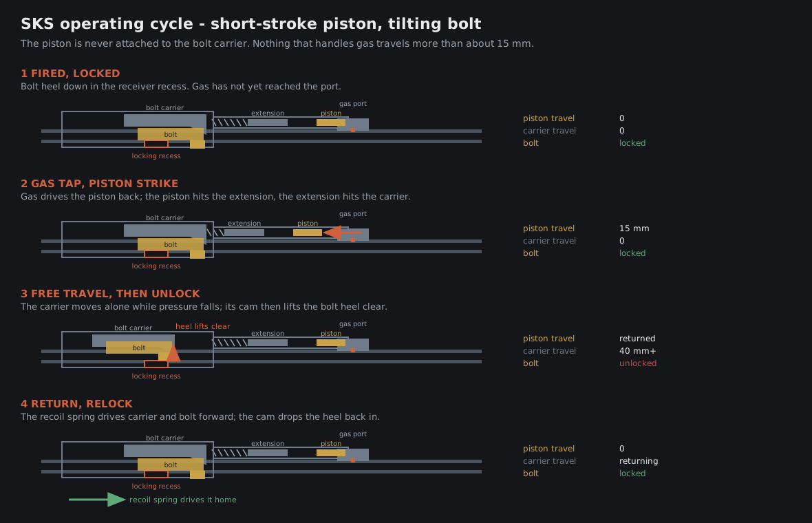
Mechanically the SKS is four things that each do one job: a short-stroke gas piston that hits something and stops, a bolt that tips instead of turning, a hammer-fired trigger group that lifts out as a unit, and a fixed magazine charged from the top. Understanding those four is understanding the rifle, and it is why the field strip in Vol 10 takes about forty seconds once you have done it twice.
9.1 The Gas System
Gas is tapped from the barrel through a port of about 2.4 mm — a figure recorded in the 1955 CIA report from the rifle’s own manual, and the sort of detail that makes that document worth having.
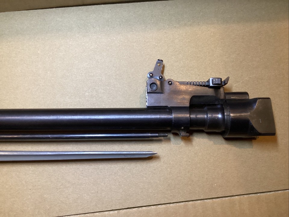
The port feeds a gas block partway along the barrel, under the front of the upper handguard. Inside sits a short gas piston. Gas drives the piston rearward a short distance — the “short stroke” — and the piston stops against its own travel limit.
What the piston hits is a separate part: the piston extension, sometimes called the op rod, which lives in the rear sight base with its own return spring. The extension is thrown back, strikes the bolt carrier, and is returned forward by its spring.
The important consequence: the piston is not connected to the bolt carrier, and neither the piston nor the extension travels the full length of the action. Total piston travel is on the order of a centimetre and a half.
Three things follow from that:
- Fouling has a short distance to matter over. The dirtiest parts move least.
- Reciprocating mass is low. A long-stroke system carries the piston all the way back with the carrier, which is more mass moving further, which is more disturbance to the sights. The SKS is measurably steadier than an AK for this reason.
- The piston can be a loose fit. It does not have to seal well, only to be hit hard and stop.
The system has no adjustment on any variant except the Yugoslav, whose grenade sight doubles as an on-off gas cut-off — Vol 8 § 8.1.
9.2 The Tilting Bolt
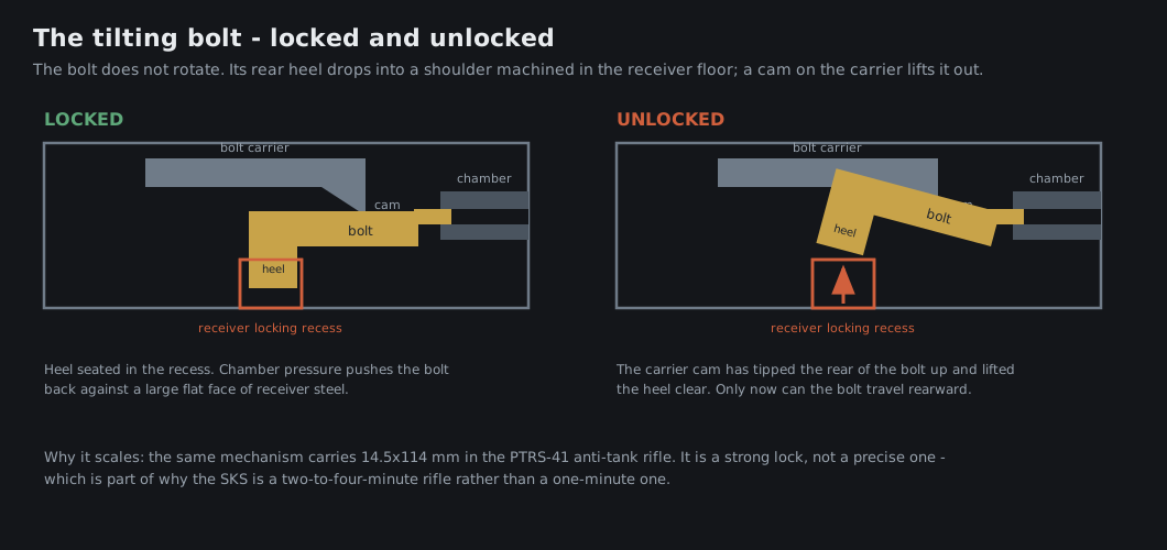
The bolt does not rotate. It tips in the vertical plane.
At lock-up, the rear underside of the bolt sits down in a recess machined into the floor of the receiver. Chamber pressure pushes the bolt back; the bolt pushes on that shoulder; the shoulder is a large flat area of receiver steel. That is the entire locking system.
To unlock, the bolt carrier moves rearward on its own for a short distance — a period of free travel during which the bolt is still locked and pressure is still falling — and then a camming surface on the carrier lifts the rear of the bolt up and out of its recess. From that point the carrier drags the bolt back with it.
Two design consequences worth noting:
The free travel is a timing device. Nothing unlocks until the carrier has moved far enough. That is how a system with no rotating lugs and no delay mechanism survives a cartridge that peaks around 45,000 psi.
The locking surface is enormous and it is in shear on one face. That is why the same mechanism scaled to 14.5×114 in the PTRS-41 without conceptual change. It is a strong lock. What it is not is a precise one — the bolt seats in the same place every time only as well as the receiver floor and the bolt’s heel agree, and that is one of the reasons the SKS is a two-to-four-minute rifle rather than a one-minute one. Vol 16 goes into that.
Return is by a recoil spring and guide assembly in the receiver behind the carrier, which comes out as one piece during the field strip.
9.3 The Trigger Group
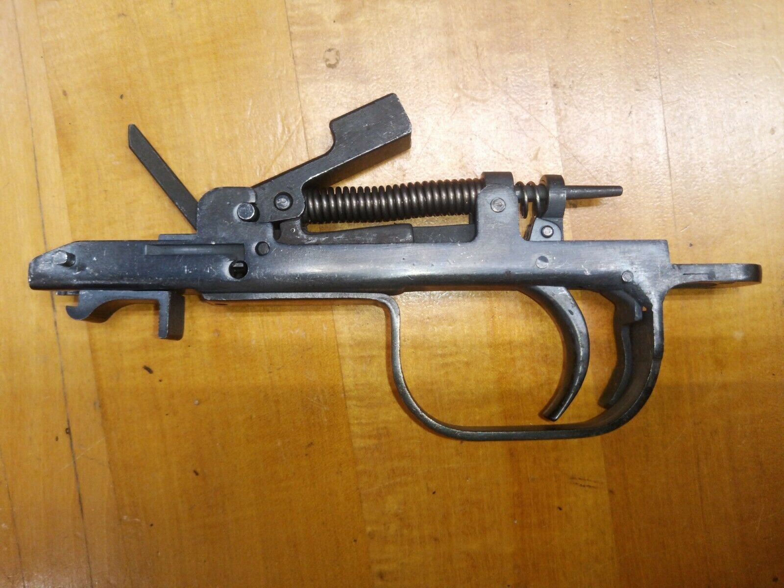
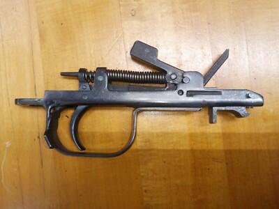
Everything that makes the rifle fire is in one removable assembly held to the underside of the receiver by hooks at the front and a latch at the rear.
Inside it: the hammer, the hammer spring, the sear, the disconnector, the trigger, the safety, and — on most patterns — the magazine catch.
The rifle is hammer-fired. The hammer is cocked by the bolt carrier on its way back, held by the sear, and released by the trigger.
The disconnector is what makes it semi-automatic and only semi-automatic. On firing, the disconnector releases the sear from the trigger so that the hammer is caught by the sear on the next cycle regardless of whether the trigger is still held. You have to release the trigger and let it reset before the sear will hand the hammer over again. That is one round per pull, mechanically enforced, and it is why the 1953 CIA report’s belief that the rifle “could be fired automatically” was never true of any version.
The safety is a lever inside the trigger guard, behind the trigger. Rotated up and forward it physically blocks the trigger from moving. It is a trigger block, not a sear block and not a firing-pin block — which is a distinction worth remembering in the context of Vol 12.
9.4 Feeding
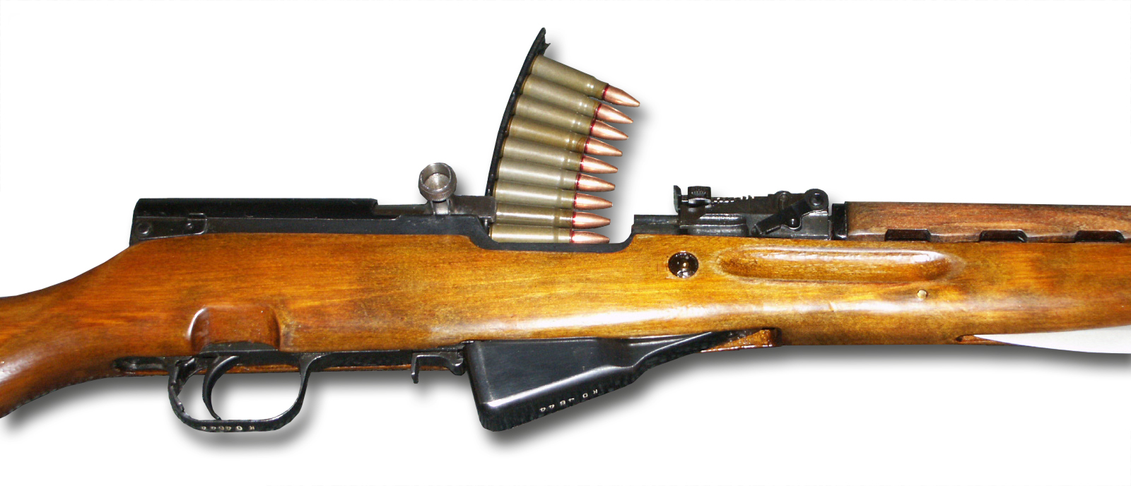
The magazine is a fixed ten-round box, hinged at its front, held closed by a catch at the rear of the trigger guard. It does not detach in normal use; it swings down and open, which is how you unload the rifle without cycling ten live rounds through the chamber.
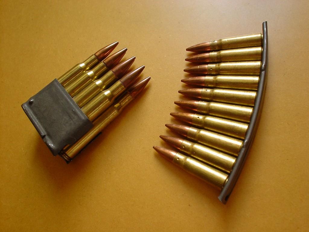
Loading is from a ten-round stripper clip, seated in a guide machined into the top of the bolt carrier. Pull the bolt back until it locks open, drop the clip into the guide, push the rounds down with your thumb, pull the empty clip out, and let the bolt go.
The 1955 CIA source recorded the load-out that goes with this system: 100 rounds as the basic combat load, carried as “three pouches, each pouch with three ten-round clips,” plus nine in the magazine and one in the chamber. That is the Chinese chest rig too, in a different pattern — ten pockets of stripper clips, which is exactly what the rifle needs and nothing that it does not.
The bolt hold-open is a small stud on the magazine follower. When the magazine empties, the follower rises and the stud catches the bolt to the rear. This is worth knowing for two practical reasons: it is why the bolt locks back on an empty magazine but not on a partly-loaded one you have hand-fed, and it is the part that most detachable-magazine conversions break, because an aftermarket magazine’s follower rarely reproduces it. Vol 15.

9.5 The Bayonet
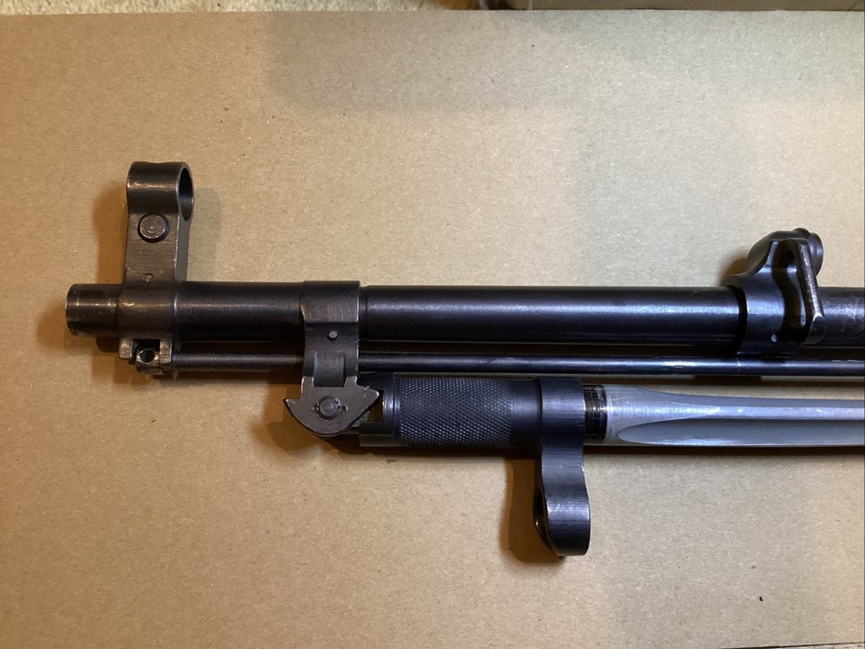
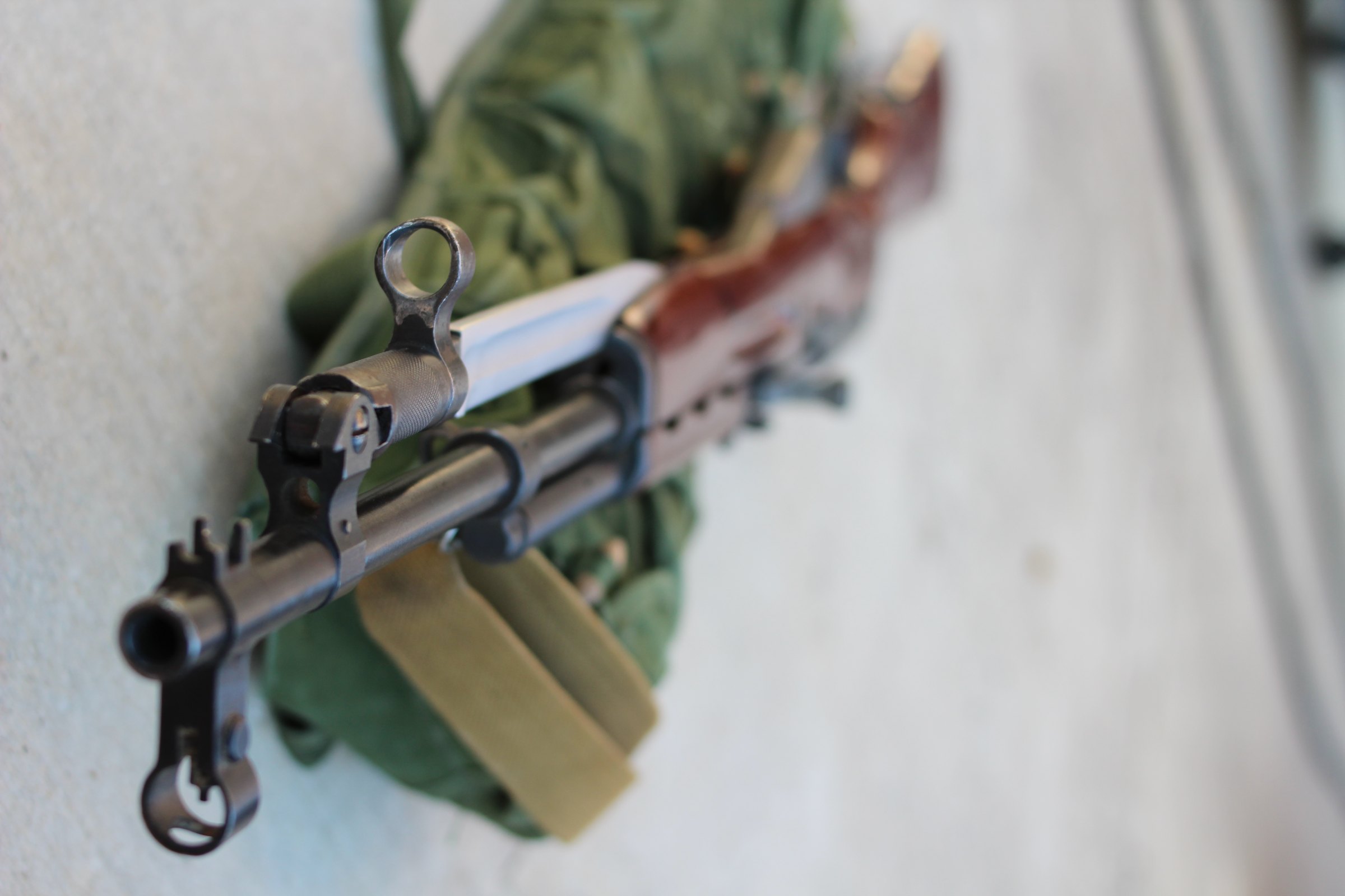
A folding bayonet, permanently attached, pivoting on a lug under the barrel and held at either end of its travel by a spring-loaded detent. Blade on Soviet post-1949 and early Chinese; four-lobed spike on the very earliest Soviet and on Chinese production from about 1964.
It is not removable without tools, which was the point — the 1953 CIA source specifically described it as “non-removable” and noted the groove in the stock it lies in when folded.
It has one practical modern consequence: the bayonet lug is what most aftermarket stocks collide with. Many synthetic stocks are made in two versions, with and without a bayonet cut, and some chassis systems will not accommodate one at all. Vol 13.
There is a persistent claim that the extended bayonet shifts point of impact. It does — it hangs about half a pound of steel off the muzzle end of a light barrel — but the effect is small at the ranges this rifle is used at and is not worth building a theory around. If you shoot with it deployed, zero with it deployed.
9.6 Sights
Front: an open post inside a circular hood, adjustable for elevation by screwing the post up or down and for windage by drifting the post’s base sideways. Both need a sight tool; the 1955 report describes the company armourer arriving with “a special vise-like tool” for exactly this.
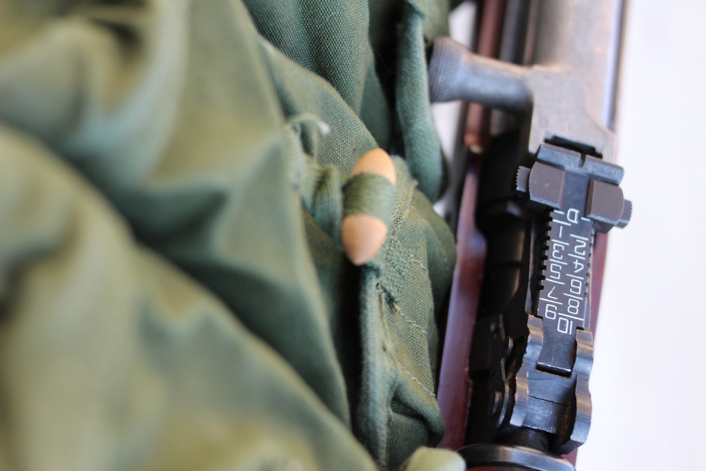
Rear: a tangent leaf graduated П (battle setting, 300 m) then 1 to 10, each numeral a hundred metres, mounted on a base ahead of the receiver. No windage adjustment at the rear at all.
The sight radius is about 480 mm, considerably longer than an AK’s, and the front post is finer. The SKS’s iron sights are genuinely better than the AK’s, and they are the main reason a good SKS out-shoots a good AK from a rest.
The rear-sight base is also a structural component: it houses the piston extension and its spring, and it carries the gas-tube locking lever. It is not just a sight.
9.7 The Whole Cycle, in Order
- Trigger releases the hammer; hammer strikes the free-floating firing pin; pin strikes the primer.
- The bullet passes the gas port; gas enters the block and drives the piston back.
- The piston strikes the piston extension; the extension strikes the bolt carrier and is returned by its own spring.
- The carrier travels rearward through its free-travel period, pressure falling, bolt still locked.
- The carrier’s cam lifts the rear of the bolt out of the receiver recess. Unlocked.
- Carrier and bolt travel back together. The extractor holds the case; the ejector strips it out through the port on the right.
- The carrier cocks the hammer, which the sear catches.
- The recoil spring returns carrier and bolt; the bolt face strips the top round from the magazine and chambers it.
- The carrier’s cam drops the rear of the bolt back into its recess. Locked.
- Release the trigger; the disconnector hands the hammer back to the trigger’s control. Ready.
On the last round, the magazine follower’s stud holds the bolt open at step 6, and the sequence stops.
Comments (0)