M1 Garand · Volume 9
Detail Strip — Bolt, Trigger Group, Gas System, Sights
Past the field strip, the M1 has four sub-assemblies that come apart further: the bolt, the trigger housing group, the gas cylinder group and the rear sight. Each has one or two parts under spring pressure that want to leave the bench at speed, and each has a job the Army kept for armorers because it wears something out if done too often. This volume goes through all four, following the manuals and noting where good shop practice improves on them.
9.1 The Bolt
9.1.1 What is in it
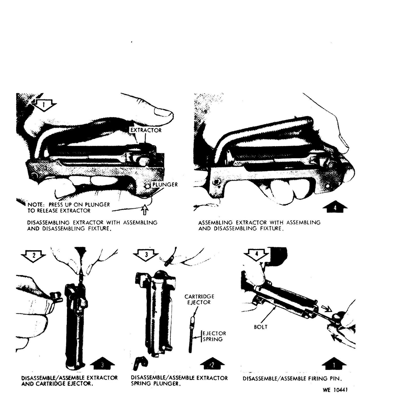
Extractor, extractor spring and plunger; ejector and ejector spring; firing pin. That is all. The extractor and ejector lock each other in: the ejector has a groove that the extractor passes over, so taking the extractor out releases the ejector under full spring pressure, and lifting the extractor frees its own spring and plunger with nothing retaining them.
Spring free lengths from the 1941 maintenance manual: extractor spring 0.485 ± 0.010 inch; ejector spring about 1.156 inch.
9.1.2 With a bolt tool
The best method for a bench is a purpose-made bolt tool, which is a version of the depot fixture above. Fulton Armory’s, made to government pattern, was $69.95 and in stock in September 2026. With the bolt in the fixture, press up on the plunger to release the extractor, lift the extractor out, and let the ejector and its spring come out under control.
9.1.3 With the combination tool
The field method uses the M3 or M10 combination tool, which has a lug made for it. Garand Gear’s cautions:
- Grease the tool surfaces lightly.
- Put the flat end with the small lug under the extractor.
- “DO NOT SLAM the bolt onto the tool!”
- Rotate counter-clockwise, using a cleaning rod section as a lever if needed.
- “Cup your left hand over the top of the bolt to catch the extractor.”
And from the 1951 field manual, the caution that actually matters: “when assembling the bolt, be careful to keep your face away from over the bolt because the ejector might fly out from under the tool.”
9.1.4 The firing pin
With the extractor and ejector out, the firing pin comes out of the rear of the bolt. Garand Gear notes that firing pins “almost always break at the rear tang.” Inspect the tip for chips and cracks and the tang for cracks, and replace a pin that shows either (the 1969 manual: “If chips or cracks are present in tip area, or if badly worn, replace”).
If a pin breaks in the rifle, the front half can wedge between the bolt and the receiver and lock the action. The 1942 ordnance manual’s advice: if the operating rod handle will not come back under a sharp blow from the heel of the hand, the firing pin may be broken; take the group out of the stock and the pin may fall out; if not, do not force it — turn the group upside down, shake it, and work the parts carefully.
9.1.5 Reassembly
Firing pin in, ejector and spring in, then the extractor with its spring and plunger, pressed home with the tool until it snaps into place over the ejector’s groove. The 1951 manual shows two methods; the fixture is easier. Check that the ejector moves freely under thumb pressure and springs back, and that the extractor snaps.
9.2 The Trigger Housing Group
9.2.1 Before you start: decock it
The hammer must be down. Hold the hammer, pull the trigger, and ease it forward. A cocked hammer in a group on the bench will take a finger.
9.2.2 Order of disassembly
From the 1951 field manual’s figure sequence, with Garand Gear’s cautions:
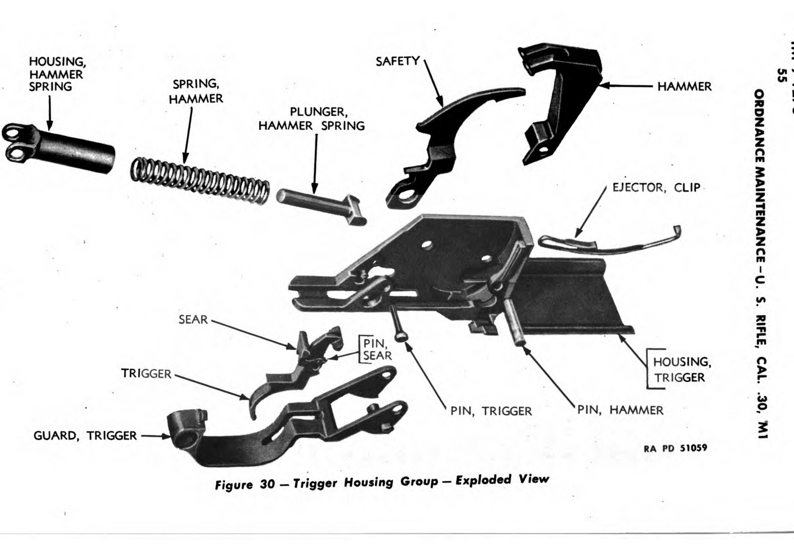
- Trigger pin. Squeeze the trigger and hammer spring housing slightly to take the load off the pin, push the pin out left to right with the drift of the combination tool or a dummy round, and slowly release the pressure. The hammer spring exerts considerable force; support the trigger and sear while the pin comes out.
- Trigger assembly and hammer spring components. Lift out the trigger assembly (trigger and sear), then separate the hammer spring plunger, hammer spring and hammer spring housing.
- Hammer pin and hammer. Push the hammer pin out left to right, move the hammer slightly back and lift it out. The hammer pin comes out one way only — one end is larger.
- Safety. Unlatch the trigger guard. With the housing on its right side, push out the safety’s stud from its hole with the drift, and lift the safety from its slot.
- Trigger guard. With the guard open, slide it to the rear until its wings line up with the safety stud hole, and rotate it up and out.
- Clip ejector. Push the clip ejector spring out of its seat.
Reassembly is the reverse. The manual’s warning for the hammer: insert it loosely, halfway between cocked and fired, so its toe clears the hammer stop on the right wing of the trigger guard; then line up the pin holes.
9.2.3 Ordnance fitting work on the group
- Filing the offset point of the clip ejector is a sanctioned depot fitting operation shown in the 1966 depot manual — for a clip ejector that does not throw clips properly.
- Peening the trigger guard lugs to take up looseness is in the 1942 ordnance manual. Vol 11.
- Trigger pull is measured with weights on the trigger. Vol 10 has the specifications, which changed between editions.
9.3 The Gas Cylinder Group
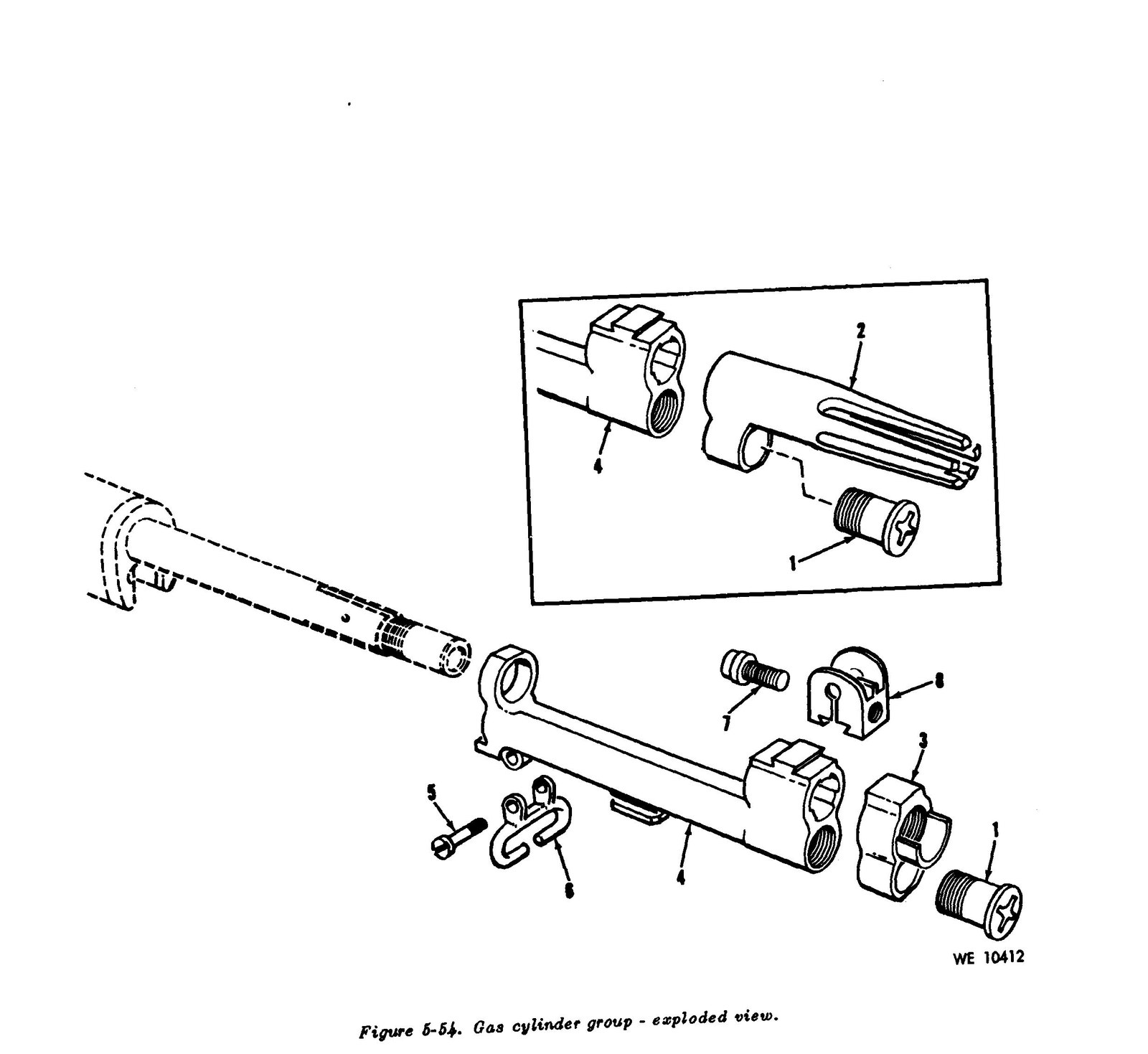
The removal sequence is in Vol 8. At the detail level:
- The front sight is held by a screw that on spline-type cylinders is sealed. The 1942 ordnance manual gives the procedure: file off the exposed surface of the seal, back out the screw with a 3⁄16-inch hex socket wrench, and when done, place a new seal over the screw head and seat it with a hammer. The manuals kept this to ordnance personnel, and so should you unless the sight actually needs to come off.
- Grenade launcher valve screws have a valve in the center. The 1944 grenade manual says flatly: “The valve will not be disassembled.” If a valve screw leaks, replace it.
- A bent gas cylinder is replaced, not straightened. The 1942 ordnance manual: “It is impracticable to straighten the gas cylinder.”
- Carbon. The 1942 manual shows removing carbon from the gas cylinder. The 1969 manual’s method is to soak carbon deposits in carbon-removing compound for two to sixteen hours, then brush under running water with a stiff bristle brush — not wire. Never use abrasives on the piston (Vol 10).
Gauging the cylinder and piston is in Vol 10; gas cylinder lock timing and loose cylinders are in Vol 11.
9.4 The Rear Sight
The 1951 field manual’s warning is the reason to leave this alone unless it needs work: “Frequent disassembly will cause stripping of the threads on the pinion; the rear sight, therefore, is disassembled only to replace parts or to clean it after use in very bad weather.”
From the 1942 ordnance manual:
- Lower the aperture as far as it will go and note the reading on the elevating knob. Write it down.
- Unscrew the rear sight nut from the right side with the combination tool.
- Unscrew the windage knob, taking care that the rear sight nut lock, inside the windage knob, is not lost. Remove the nut lock and its spring.
- Remove the elevating knob screw from the left side with a screwdriver, and remove the elevating knob.
- Pull out the elevating pinion from the left.
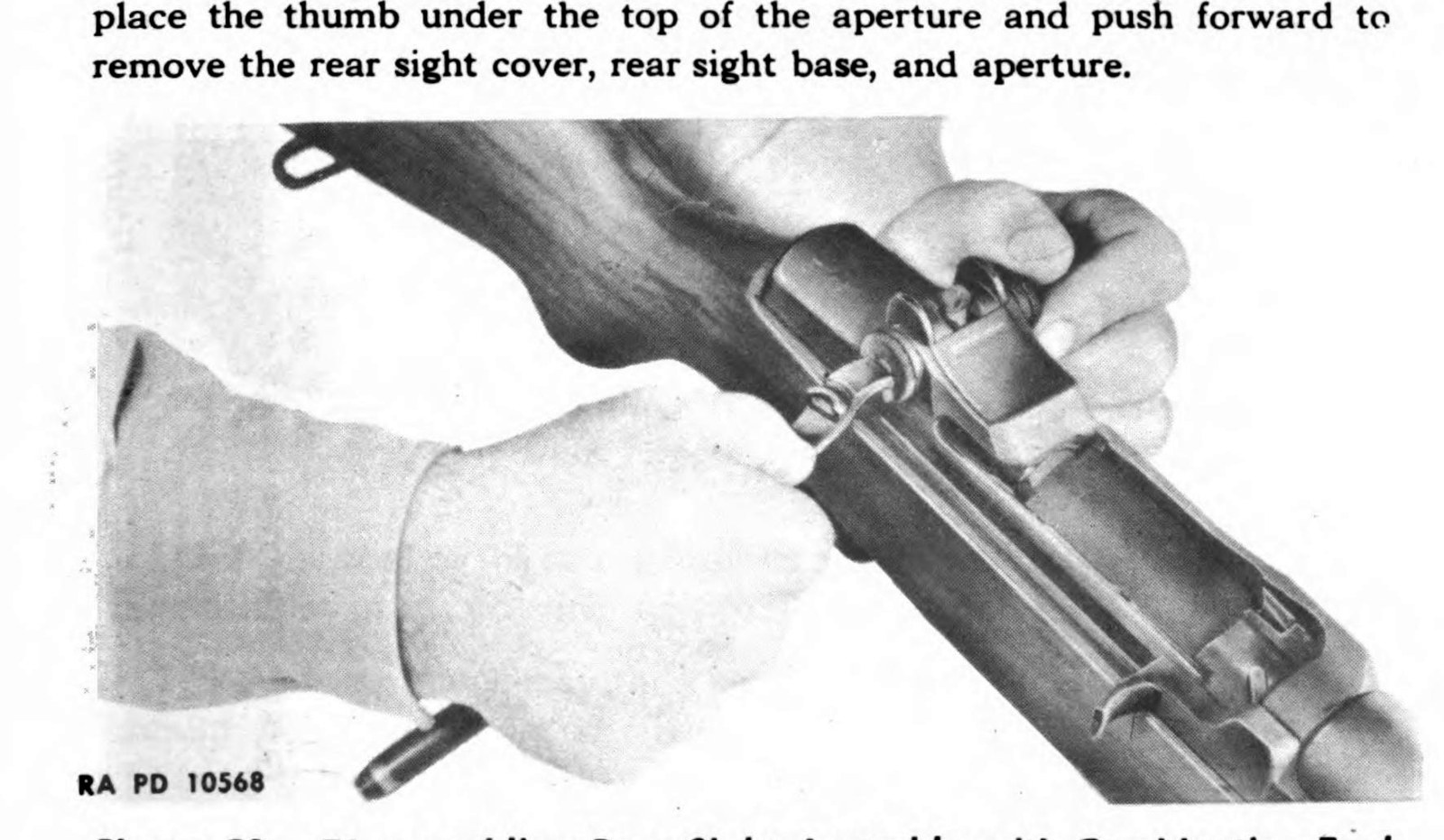
- Grasp the aperture and pull it up about half an inch; then put your thumb under the top of the aperture and push forward to remove the rear sight cover, base and aperture together.
Garand Gear’s addition for reassembly: “apply a thin coating of grease on the detents.” The spring behind the nut lock has a specification in the 1941 manual — compressed to 0.160 inch, it should carry 6 to 8 pounds.
After reassembly, set the sight tension (Vol 10) and re-zero.
9.5 The Clip Latch
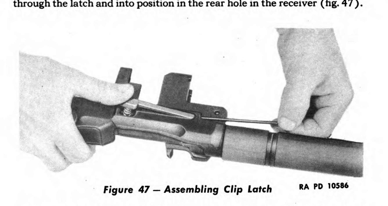
The clip latch is held on the left side of the receiver by a pin driven out forward with a drift, while you press in on the latch to relieve its spring. Its spring’s free length is about 0.453 inch (1941 manual). Garand Gear’s inspection point: the latch’s lug “must remain square with well-defined edges” — a rounded lug will not hold a clip, and a clip that jumps out early is one of the commonest M1 complaints (Vol 11).
To reassemble, per the 1942 manual: with the barrel and receiver group lying on its right side, place the latch and spring on the left side of the receiver, insert the pin from the front, locate it in the latch’s forward hole, and press lightly on the rear of the latch to relieve the spring while pushing the pin through into the rear hole.
9.6 The Follower and Slide
The slide comes off the follower only at the maintenance level. To put it back, from the 1942 ordnance manual: hook the slide in place in the small end of the follower, stand the two pieces on end (or hold them at an angle in a vise), and deliver a sharp blow on the rear end of the slide; it snaps back into position.
Sources
- U.S. War Department, TM 9-1275, U.S. Rifle, Cal. .30, M1 (December 1941 and November 1942 editions), paragraphs 53, 55, 65–66 and 77–78.
- U.S. Department of the Army, TM 9-1005-222-35 (1966), bolt, trigger housing and gas cylinder figures.
- U.S. Army, FM 23-5 (1951), paragraphs 13, 16 and 22, and figure sequence 14–34.
- U.S. Army, TM 9-1005-222-12 (1969), cleaning and inspection tables.
- U.S. War Department, FM 23-30, Hand and Rifle Grenades (1944), on the valve screw.
- Garand Gear, “M1 Garand Strip” and “M1 Garand Inspection.”
- Fulton Armory, bolt assembly/disassembly tool listing, checked September 14, 2026.
Comments (0)