M1 Garand · Volume 8
Field Strip
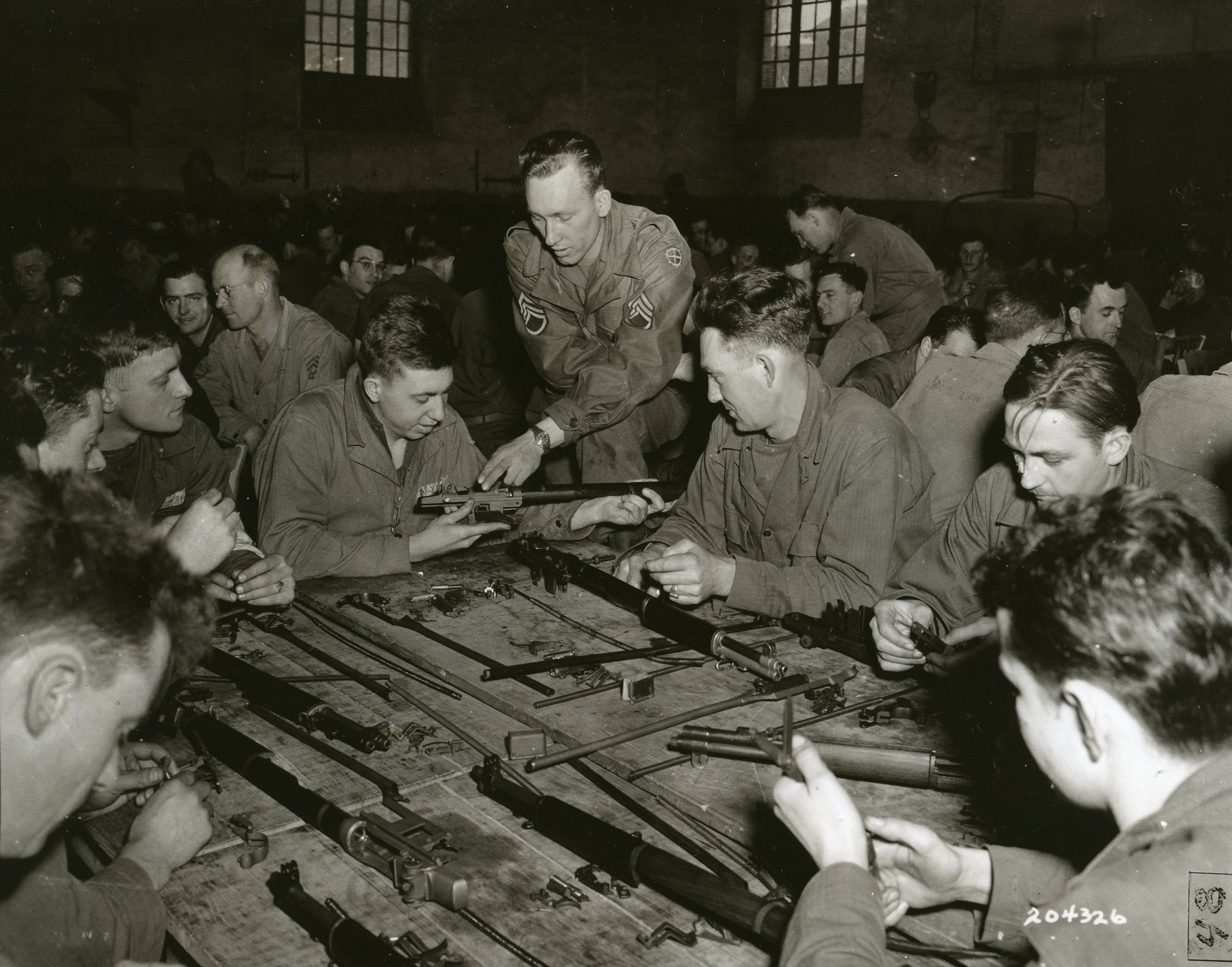
An M1 field strips without tools into three groups, and a soldier was authorized to take the barrel and receiver group further — bolt, operating rod, follower parts and gas cylinder — with nothing but the tip of a cartridge and the combination tool. This volume is that sequence, following the Army’s 1965 field manual step by step, with the cautions that matter and the places where the manuals disagree with each other.
The manuals are firm about one thing throughout: no force. The 1940 edition: “The rifle can be readily disassembled and assembled without applying force. Such practice is prohibited.” If something will not move, something is not aligned.
8.1 Who May Take What Apart
The 1965 manual’s Table I sets out what the soldier, the unit armorer, and ordnance maintenance personnel were each allowed to do.
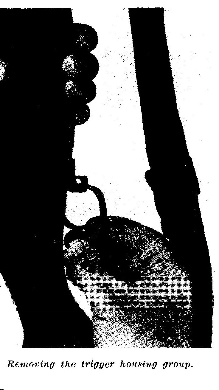
Table 1 — Who May Take What Apart
| Part | Individual soldier | Armorer | Maintenance personnel |
|---|---|---|---|
| Three main groups; barrel and receiver group | Separate | ||
| Bolt assembly | Remove | Repair | Repair/replace |
| Gas cylinder | Remove | Repair | Repair/replace |
| Gas cylinder lock | Remove | Remove | Repair/replace |
| Clip latch | — | Repair | Repair/replace |
| Rear sight | — | Repair | Repair/replace |
| Slide from follower | — | — | Repair/replace |
| Accelerator from operating rod catch | — | — | Repair/replace |
| Front sight | — | — | Repair/replace |
| Trigger housing group | Remove | Repair | Repair/replace |
For someone with a gunsmith’s bench, the table is not a restriction. It is a map of where the parts are delicate: the rear sight, the follower slide, the accelerator and the front sight are the jobs the Army kept away from riflemen for a reason.
8.2 Before You Start: Clear It
- Pull the operating rod handle fully to the rear. On an empty rifle the bolt locks open.
- Look into the chamber and the receiver. Then feel.
- Push the safety to its locked position — back, inside the front of the trigger guard.
8.2.1 Letting the bolt forward without losing a thumb
The 1965 manual says to let the bolt forward “by depressing the follower with the right thumb and allowing the bolt to ride forward over the follower assembly.” That is the moment that gives people M1 thumb: the operating rod spring drives the bolt forward hard, and a thumb left in the receiver is caught between the bolt and the receiver.
The safe version:
- Hold the operating rod handle back with the heel or knife-edge of your right hand while your thumb presses the follower down.
- Sweep the thumb out to the right as the follower is released, and let the handle ride forward against your hand instead of slamming.
- The same technique works when loading a clip: push the clip down with the thumb, block the handle with the side of the hand, and roll the thumb out.
8.3 The Three Main Groups
8.3.1 Trigger housing group
Place the rifle butt against your left thigh, sights to the left. With the thumb and forefinger of the right hand, pull downward and outward on the rear of the trigger guard. Swing the guard out as far as it will go and lift out the trigger housing group.
8.3.2 Stock group
Lay the rifle on a flat surface, sights up, muzzle to the left. With the left hand, grasp the rear of the receiver and raise the rifle. With the right hand, give a downward blow on the small of the stock. The barrel and receiver group comes out of the stock.
The 1942 ordnance manual describes it the other way round — rifle upside down, lift the stock off by the butt end. Either works; both are without tools.
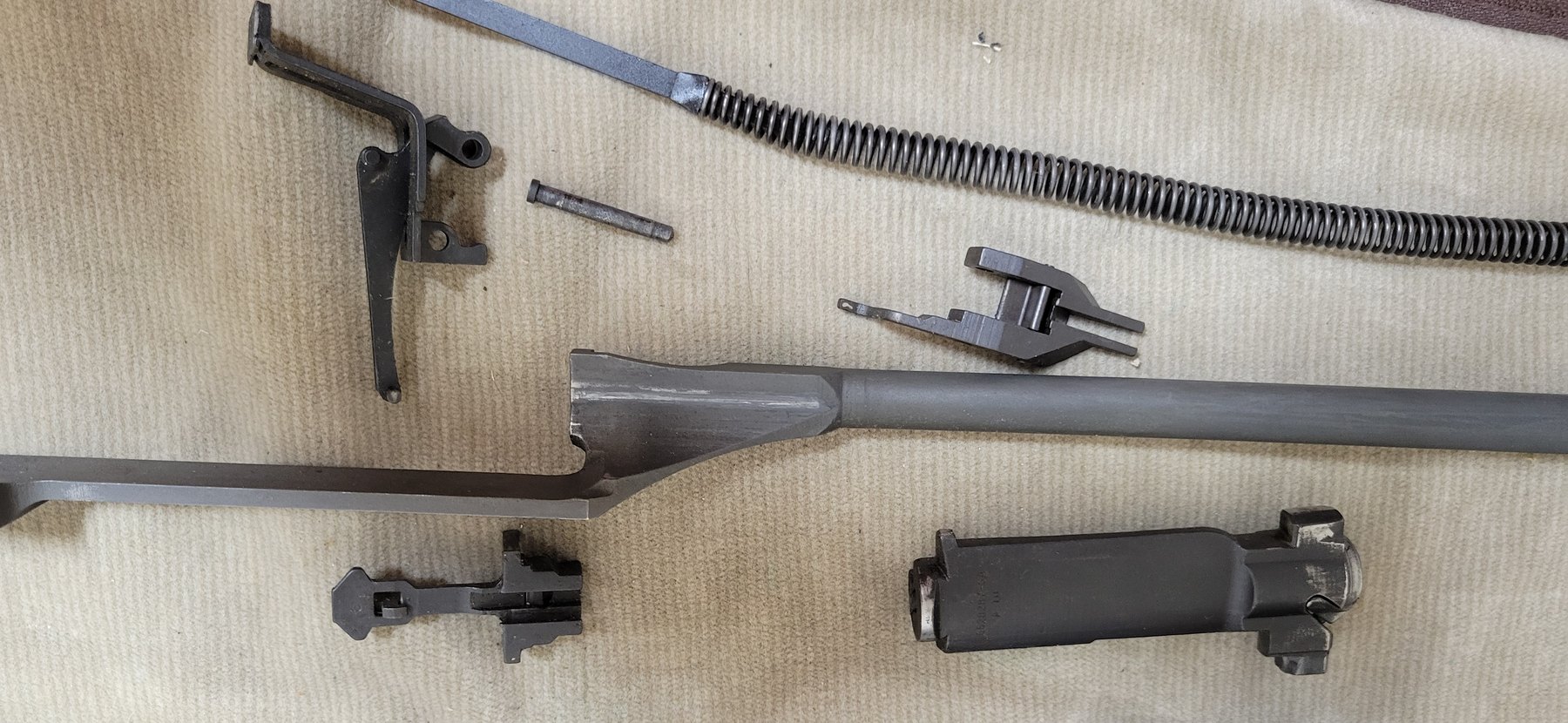
8.4 The Barrel and Receiver Group
8.4.1 Follower rod and operating rod spring
Lay the group with the bolt closed on a flat surface, sights down — with the rear aperture at its lowest position so it is not damaged — muzzle to the left.
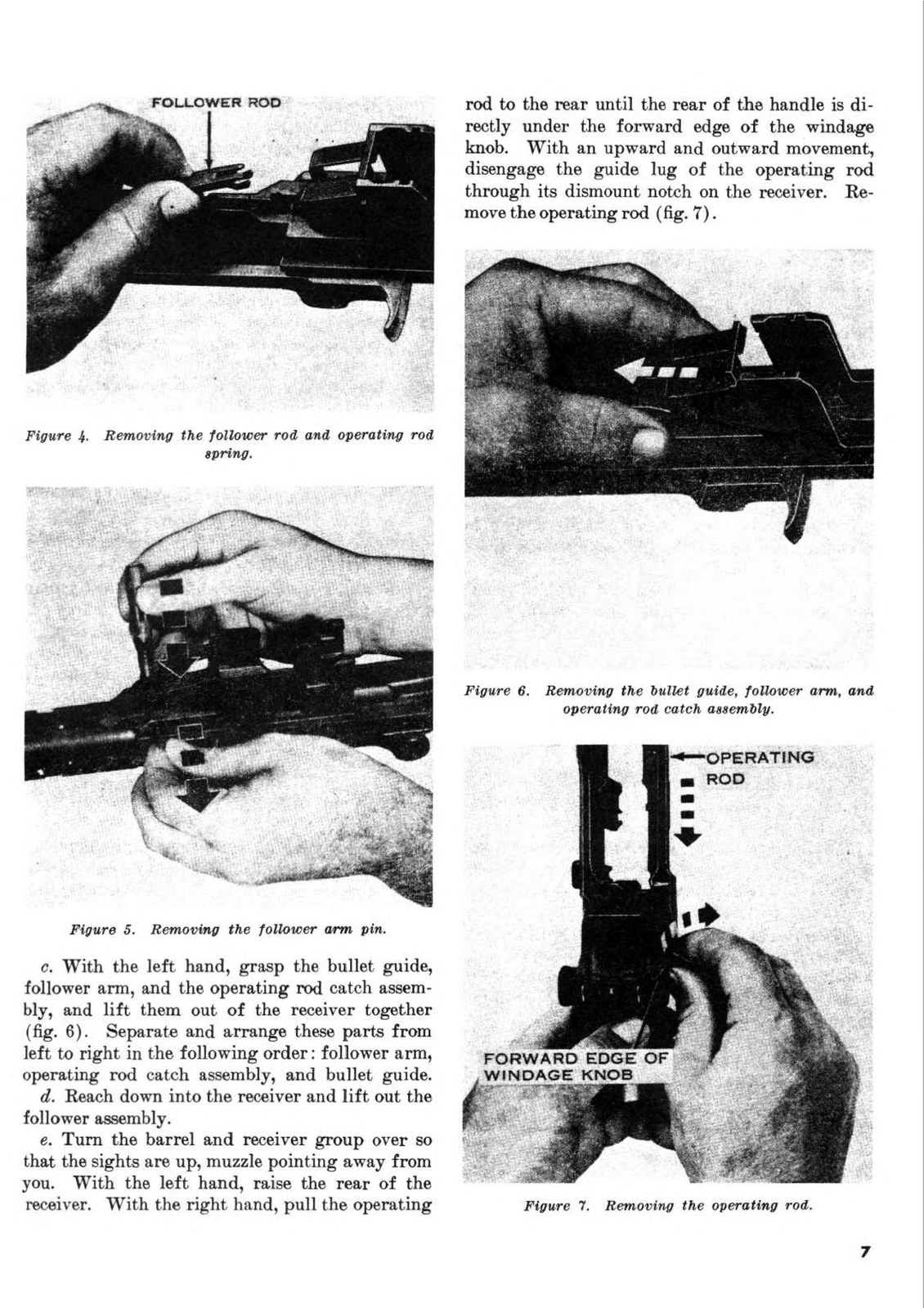
Hold the rear of the receiver with the right hand. With the thumb and forefinger of the left hand, grasp the follower rod and disengage it from the follower arm by moving it toward the muzzle. Withdraw the follower rod and operating rod spring to the right. Do not separate them.
8.4.2 Follower arm pin
Using the tip of a dummy cartridge, push the follower arm pin from the far side of the receiver toward you.
8.4.3 Bullet guide, follower arm and operating rod catch
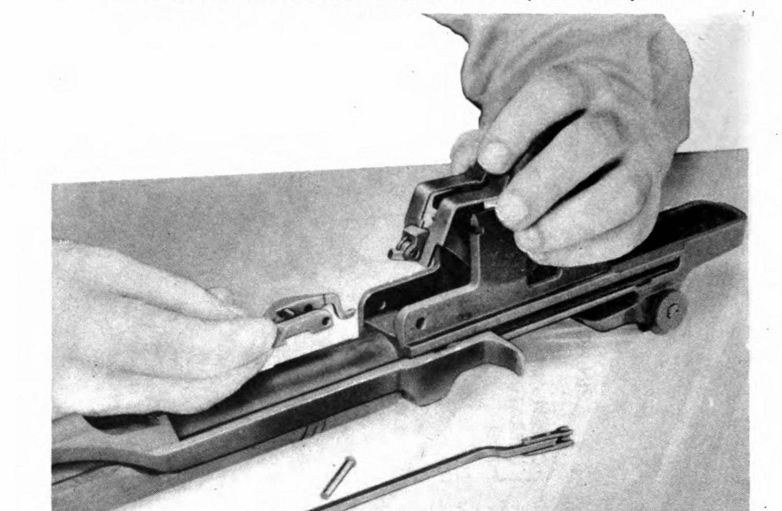
With the left hand, grasp the bullet guide, follower arm and operating rod catch assembly and lift them out together. Lay them out from left to right: follower arm, operating rod catch assembly, bullet guide. Then reach into the receiver and lift out the follower assembly.
The 1942 ordnance manual adds: “Do not disassemble the accelerator from the operating rod catch.”
8.4.4 Operating rod
Turn the group over so the sights are up and the muzzle points away from you. With the left hand, raise the rear of the receiver. With the right hand, pull the operating rod to the rear until the rear of the handle is directly under the forward edge of the windage knob. With an upward and outward movement, disengage the rod’s guide lug through its dismount notch in the receiver and remove the rod.
Caution (FM 23-5, 1965): “The operating rod is bent intentionally so that it will not bind against the enlarged portion of the barrel. Do not attempt to straighten it.”
If the rod does not come free, it is not at the notch. Never force an operating rod out of the rifle — that is one of the ways rods get bent. The 1942 ordnance manual locates the notch as the point about half an inch short of the rod’s rearmost position.
8.4.5 Bolt
The 1965 manual: grasp the bolt by the operating lug and slide it fully to the rear; then slide it forward, lifting upward and outward to the right front with a slight rotating motion.
The 1942 ordnance manual describes the bolt going the other way: with the group right side up, pull the bolt forward about an inch, tilt it upward about 15 degrees, and slide it out forward. Both work in practice. Use whichever your hands find natural, and do not force it.
8.4.6 Gas cylinder
Only when necessary — the 1951 manual says “Do not remove the gas cylinder except when necessary” — and only after the operating rod is out.
- Unscrew the gas cylinder lock screw with the screwdriver blade of the cleaning rod handle or combination tool.
- Unscrew the gas cylinder lock. It is a right-hand thread; looking at the muzzle, it turns counter-clockwise to come off.
- Tap the gas cylinder lightly toward the muzzle with a piece of wood on the bayonet stud until it loosens, and slide it off. Be careful not to burr the splines.
Two cautions from the manuals:
- On gas cylinders modified with a cut from the front sight dovetail down to the lower splines, the 1951 manual says to loosen the front sight screw before removing the cylinder.
- Do not remove or adjust the front sight. On spline-type cylinders its screw is sealed.
A shop tip from Garand Gear worth adopting: support the gas cylinder with a gas cylinder wrench while breaking the lock screw loose, so the twisting force does not go into the barrel splines.
8.4.7 Front handguard
Slide the front handguard forward off the barrel. The 1965 manual says: do not attempt to remove the rear handguard.
8.5 Reassembly
Reverse the order. The places where people go wrong:
8.5.1 Gas cylinder
- Slide the front handguard on until it seats in the front band.
- Align the gas cylinder’s splines with the grooves on the barrel and push it on. If it needs a tap, use wood on the bayonet stud.
- Screw the gas cylinder lock on by hand until finger tight — no tools. If the lock does not line up with the gas cylinder, do not force it; unscrew it until it does.
- Replace and tighten the lock screw with the cleaning rod handle.
Armorers’ practice on how tight the lock should be, and why the 1965 manual’s “finger tight” differs from it, is in Vol 11.
8.5.2 Bolt
Hold the bolt by the operating lug and place its rear end on the bridge of the receiver. Rotate it counter-clockwise until the firing pin tang clears the top of the bridge. Guide the left locking lug into its groove on the left side of the receiver, lower the right locking lug onto its bearing surface, and slide the bolt halfway to the rear.
8.5.3 Operating rod
Hold the rod by the handle, put the piston into the gas cylinder, and fit the recess in the hump over the bolt’s operating lug. Then — the manual’s words — “While applying pressure downward and inward on the handle, pull the operating rod to the rear until the guide lug is engaged in its groove.” Move the rod forward until the bolt is closed.
8.5.4 Follower assembly
Turn the group sights down, muzzle left. Replace the follower so its guide ribs fit the grooves in the receiver, with the slide down and the square hole to the rear. Garand Gear warns that it is possible to put it in upside down. The slide rests against the bolt.
8.5.5 Bullet guide and operating rod catch
Replace the bullet guide so its shoulders fit its slots and the hole in its toe lines up with the holes in the receiver. Then lift the lower part of the bullet guide slightly and insert the rear arm of the operating rod catch through the clearance cut in its side, so that the rear arm is underneath the front stud of the clip latch. Lower the bullet guide.
Test it: press down on the front arms of the operating rod catch. They should move, against the tension of the clip latch spring. If they do not, the catch is not under the clip latch stud.
8.5.6 Follower arm
Pass the follower arm’s rear studs through the bullet guide into the guide grooves on the follower, with the arm’s wings astride the toe of the bullet guide. Line up the holes and push the follower arm pin in from the near side.
8.5.7 Follower rod and spring
Put the loose end of the operating rod spring into the operating rod. Insert the follower rod into the spring with its hump toward the barrel. Pull toward the muzzle to compress the spring, and engage the claws of the follower rod with the front studs of the follower arm. Raise the follower slightly to check.
8.5.8 Stock and trigger housing
Put the barrel and receiver group back into the stock. Open the trigger guard fully, lower the trigger housing straight down so its lugs enter their recesses, and close the guard. The manual’s detail about position is there for a reason: do this with the butt against the left thigh, sights to the left, “so that the rear sight will not be damaged.”
8.6 Function Check
From the 1965 manual:
- Pull the operating rod fully to the rear. The bolt should stay open.
- Close the bolt, put the safety on, and squeeze the trigger. The hammer must not fall.
- Take the safety off and squeeze. The hammer falls.
The 1969 operator’s manual adds: the safety will not engage when the hammer is forward. This volume adds one more, the check that catches doubling: hold the trigger back, cycle the operating rod, and release the trigger slowly. The hammer should stay back through the cycle and you should feel it reset from the sear to the trigger. If it follows the bolt down, stop — Vol 11.
8.7 Removing the Bolt Without a Full Strip
The 1942 ordnance manual describes a shortcut: unhook the operating rod spring from the follower rod, depress the follower, and withdraw the bolt, taking care not to let the rod spring forward and bend. The manual recommends it “only where limited time is available.” It is not a shortcut to make a habit of.
Sources
- U.S. Department of the Army, FM 23-5, U.S. Rifle, Caliber .30, M1 (1965), paragraphs 6–11 and Table I.
- U.S. War Department, FM 23-5 (1940, 1951 editions).
- U.S. War Department, TM 9-1275, U.S. Rifle, Cal. .30, M1 (November 1942), paragraphs 48–50 and 54.
- U.S. Army, TM 9-1005-222-12 (1969), preventive maintenance checks.
- Garand Gear, “M1 Garand Strip” and “M1 Garand Inspection.”
- m1-garand-rifle.com, “Loading.”
Comments (0)