M1 Garand · Volume 5
How It Works
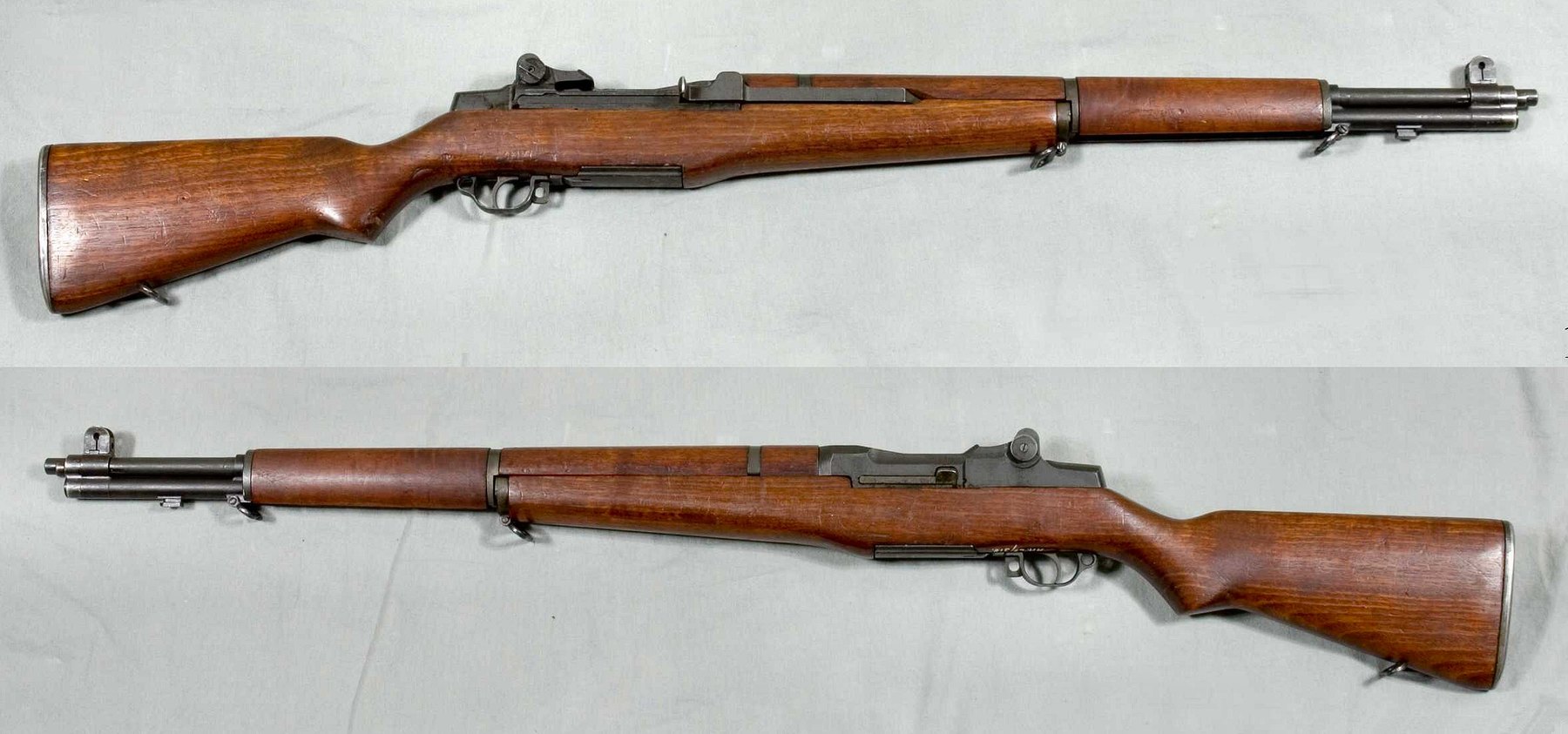
The M1 has fewer parts than it looks like it should, and every one of them does something you can see if you hold the rifle upside down with the stock off. This volume is the mechanism: the three groups the rifle comes apart into, the gas system, the bolt and how it locks, the en-bloc clip and what happens on the last round, and the trigger group that keeps the rifle semi-automatic. Vols 8 and 9 take it apart; this one explains what you are looking at when you do.
5.1 Three Groups
The rifle separates, without tools, into three groups:
- The trigger housing group — trigger, hammer, sear, safety, the hammer spring, the trigger guard that locks the group in, and the clip ejector.
- The stock group — the stock, buttplate, rear handguard and the hardware that holds them.
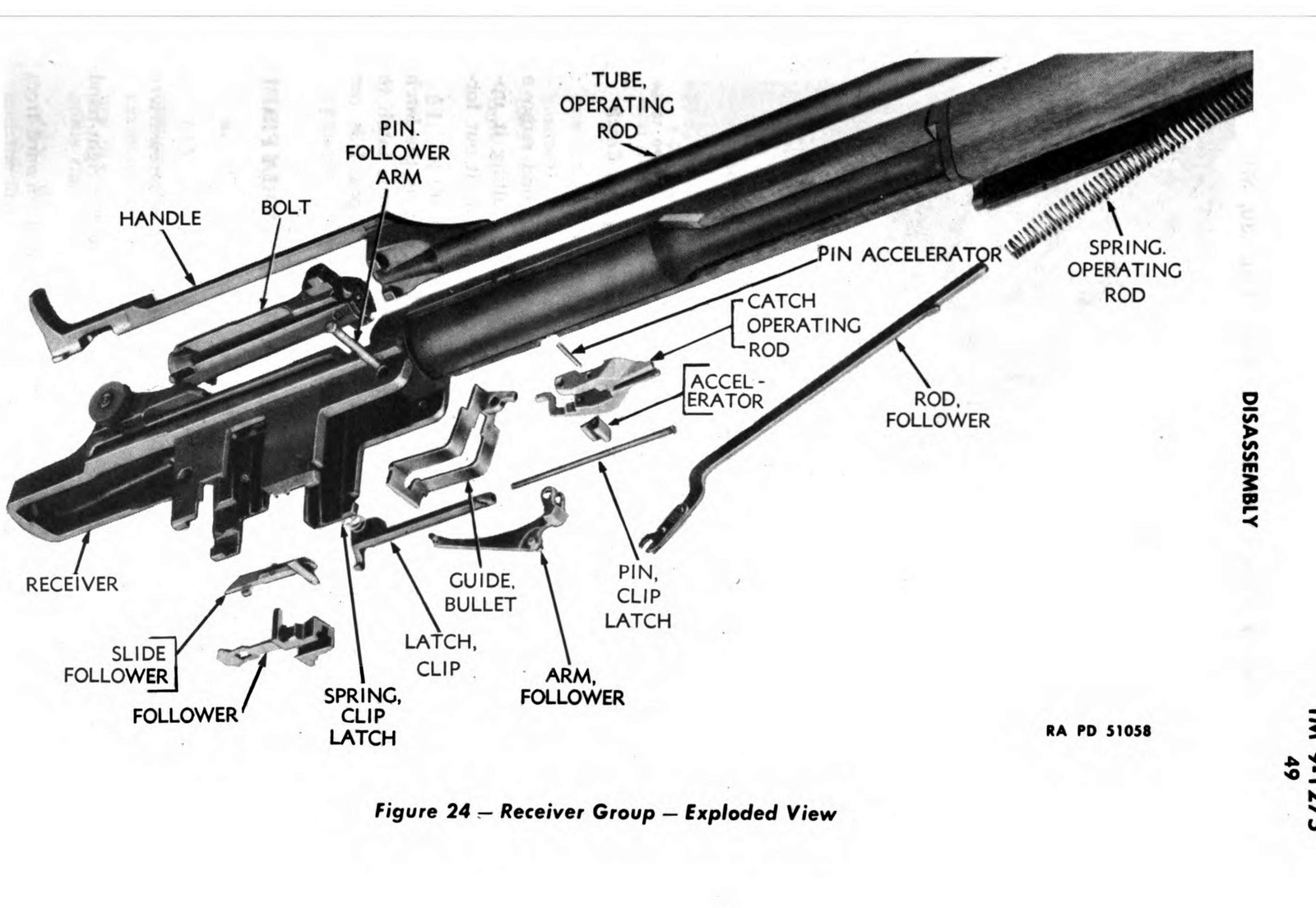
- The barrel and receiver group — everything else: barrel, receiver, bolt, operating rod and its spring, follower and follower rod, bullet guide, operating rod catch, clip latch, gas cylinder, rear and front sights, and the front handguard.
The trigger guard is the latch for the whole rifle. Swing it open and the trigger housing lifts out; with the trigger housing out, the barrel and receiver group lifts out of the stock. Vol 8.
5.2 The Cycle
The 1965 field manual teaches the cycle of operation in eight steps. Here they are, with what each part is doing.
Feeding. Eight rounds sit in the en-bloc clip in the magazine. The follower, pushed up by the follower arm and the operating rod spring acting through the follower rod, lifts the top round into the path of the bolt.
Chambering. The operating rod spring drives the operating rod forward, and the rod carries the bolt with it. The bolt strips the top round from the clip and pushes it into the chamber. As the round seats, the extractor snaps over the rim and the spring-loaded ejector is pressed back into the bolt face.
Locking. Near the end of its travel, a camming surface inside the hump of the operating rod bears on the bolt’s operating lug and rotates the bolt. The two locking lugs on the bolt turn into recesses in the receiver. The rifle is locked.
Firing. The trigger releases the hammer, and the hammer, driven by the hammer spring, strikes the tang of the firing pin.
Unlocking. As the bullet passes the gas port near the muzzle, gas bleeds into the gas cylinder and drives the operating rod’s piston rearward. The first part of the rod’s travel is free; then the cam surface in the hump lifts the bolt’s operating lug, rotating the locking lugs out of the receiver recesses. The rifle is unlocked, and by now the bullet is gone and chamber pressure has fallen.
Extracting. The rod and bolt travel rearward together. The extractor pulls the fired case from the chamber.
Ejecting. As the case mouth clears the chamber, the compressed ejector throws it up and to the right.
Cocking. The rear of the bolt rides over the hammer and forces it back, compressing the hammer spring. The operating rod spring is compressed at the same time, and at the end of travel it drives the rod and bolt forward to begin the next cycle.
5.2.1 Why it only fires once
The hammer can be caught two ways. If you are still holding the trigger when the bolt cocks the hammer, the sear catches it. When you release the trigger, the hammer slips from the sear to the trigger lugs (the hooks on the trigger), and the rifle is ready to fire again. That two-catch arrangement — the manual’s point, and the heart of the trigger group — is what prevents the rifle firing automatically. It is also why worn hammer hooks or a worn sear can make an M1 double (Vol 11).
5.3 The Gas System
5.3.1 Where the gas comes from
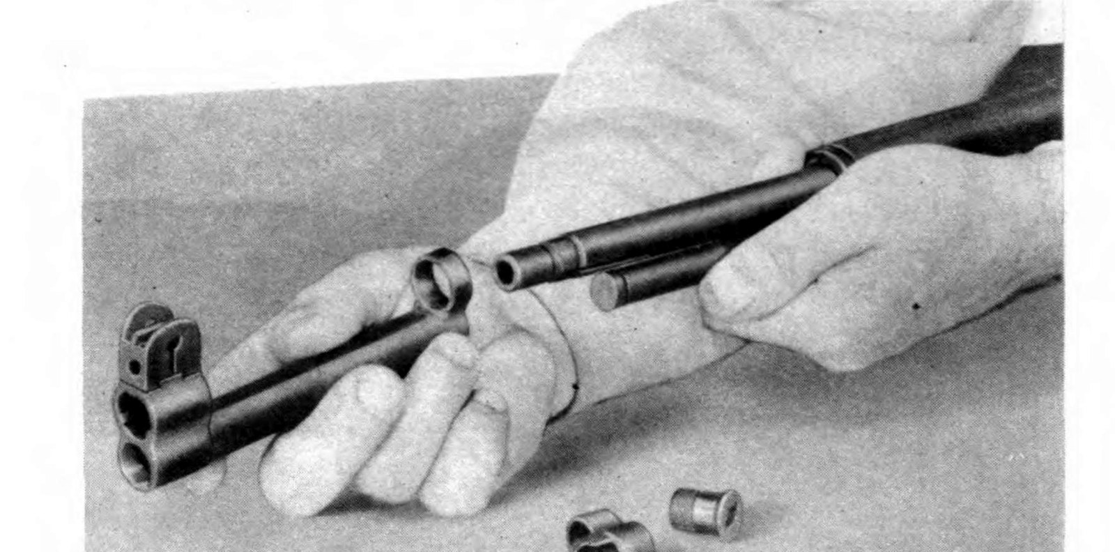
The gas port is a small hole in the underside of the barrel near the muzzle. The gas cylinder is a steel sleeve that slides over the muzzle end of the barrel, located by splines on the barrel and held on by the gas cylinder lock, which screws onto the barrel’s threads. The gas cylinder lock screw closes the front of the cylinder. The front sight is mounted on the gas cylinder, and so is the bayonet lug.
This arrangement replaced the rifle’s original gas trap — a muzzle cap that caught gas at the muzzle rather than through a port — in 1940. The early design used a gas cylinder plug and had the front sight screw entering from the side; the later spline type has the barrel protruding past the cylinder and the front sight screw entering from the rear, sealed. Vol 3 has why it changed.
5.3.2 The operating rod
The operating rod is one forging: a piston at the front that runs in the gas cylinder, a long tube, a hump at the rear with the cam track for the bolt, and the handle. The rod’s guide lug rides in a groove on the right side of the receiver, and a dismount notch in that groove is the only place the rod can come out.
The rod is bent on purpose. Every edition of the manuals says so. The 1965 field manual: “The operating rod is bent intentionally so that it will not bind against the enlarged portion of the barrel. Do not attempt to straighten it.” The 1942 maintenance manual says the same thing. Seen from the top, a good rod looks straight; seen from the side, its two bends show.
Wartime rods could crack at the right angle where the handle meets the tube. Post-war rods carry a stress-relief cut there; the final design, drawing number 7790722, is the one on the rifle documented in Vol 7, stamped NM.
5.3.3 The timing, and why ammunition matters
The gas event is brief. One detailed analysis puts peak gas-cylinder pressure at about half a millisecond after the cylinder starts to fill, and near zero by three milliseconds, during which the operating rod has moved only about three-eighths of an inch. The rest of its travel is momentum. That is why the rifle is sensitive to how much powder is still burning when the bullet reaches the port — and why the wrong ammunition can hit the rod much harder than the rifle was designed for. Vol 12 is about that.
5.3.4 The grenade launcher valve
Some gas cylinder lock screws have a valve in the center. It belongs to the grenade launcher: when the M7 launcher was fitted, a stud on the launcher pushed into the valve screw and held the valve open, venting gas so the rifle would not cycle — and batter itself — when firing grenades. The rifle became a single-shot. Vol 15. A valve that does not fully seat will leak gas and cause short-stroking (Vol 11).
5.4 The Bolt and Firing Pin
The bolt has two locking lugs, an operating lug that the rod’s cam acts on, an extractor on the right with its spring and plunger, a spring-loaded ejector in the bolt face, and a firing pin running through the middle.
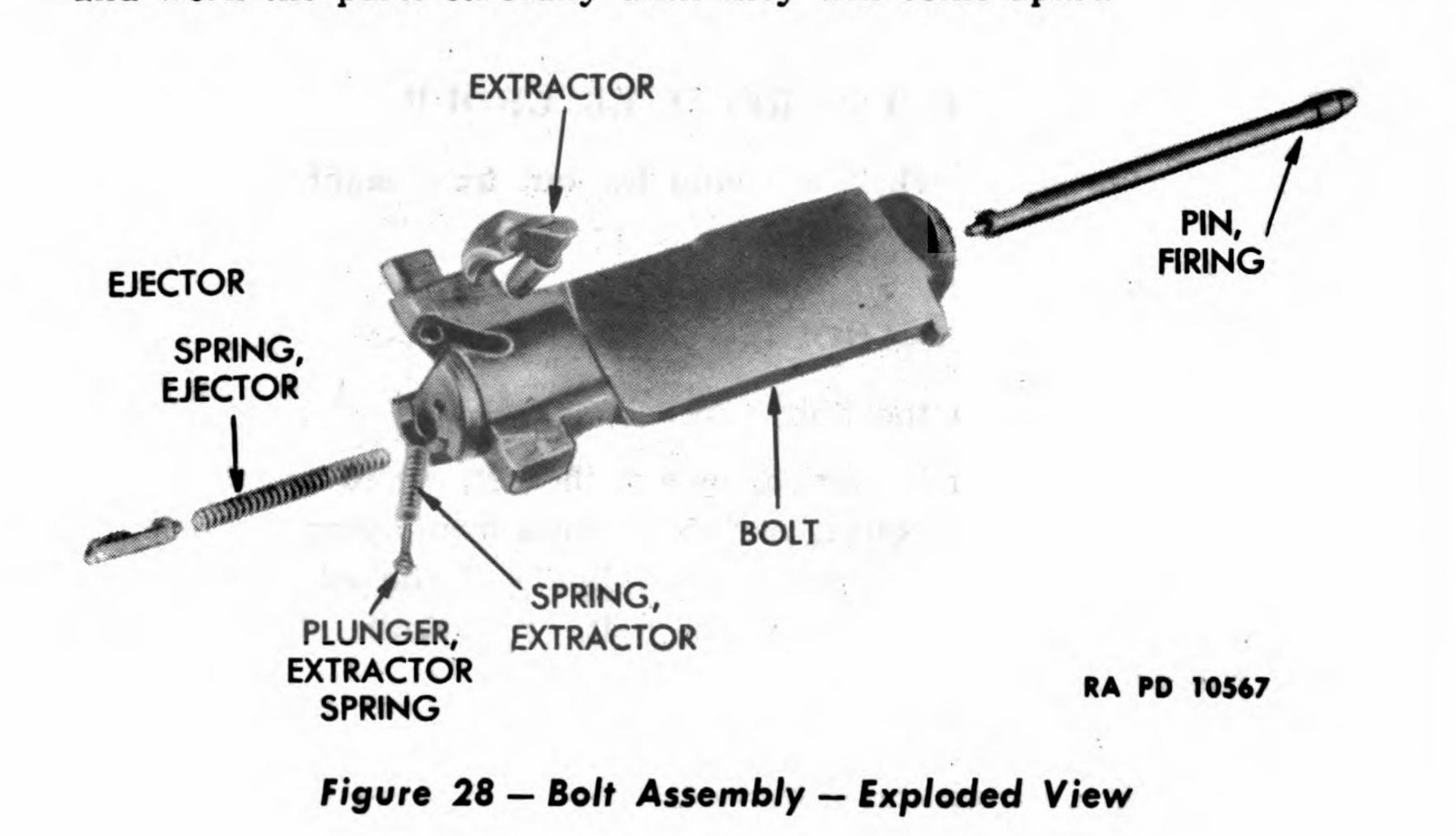
The firing pin floats. No spring holds it back. When the bolt slams a round into the chamber, the pin’s inertia carries it forward against the primer. That is normal, and it is why M1 handloaders care about primer sensitivity and seating depth (Vol 13).
The rifle has two independent mechanical safeguards against firing before it is locked:
- The firing pin tang and the receiver bridge. The rear of the firing pin has a tang that must line up with a notch in the receiver bridge. Until the bolt has rotated into lock, the bridge blocks the tang, and the pin cannot go forward far enough to fire.
- The hammer’s camming lug. If the bolt is not locked, the hammer strikes the rear of the bolt rather than the firing pin.
Firing-pin protrusion — how far the pin stands out of the bolt face when fired — was 0.030 to 0.065 inch in the 1941 manual and 0.044 to 0.060 inch in the 1966 depot manual. The later figure is the one to use. Vol 10.
5.5 The Clip, the Follower, and the Last Round
The en-bloc clip holds eight rounds and goes into the rifle with them. It stays in the magazine while the rifle fires and is thrown out when it is empty. The clip is held down by the clip latch on the left side of the receiver.
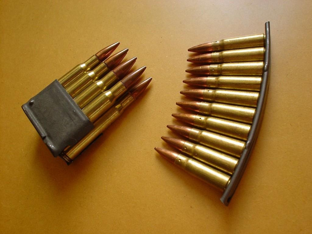
Under the clip are the follower (with its slide), the follower arm, the follower rod with its claws engaging the follower arm, and the bullet guide, all retained by the follower arm pin. The operating rod catch rides with them; its rear arm passes through a clearance cut in the bullet guide and sits under the front stud of the clip latch.
When the last round is fired, the follower rises to the top of its travel. The operating rod catch engages the rod and holds the rod and bolt open, and the clip ejector — a spring part in the trigger housing group, not in the receiver — throws the empty clip up out of the rifle. That is the ping.
Loading a fresh clip pushes down on the follower and, through the linkage, releases the operating rod catch. The bolt goes forward under full spring pressure and chambers a round. If your thumb is still in the receiver, the bolt catches it on the way — “M1 thumb” — which is why the loading technique in Vol 8 matters.
5.6 The Trigger Group
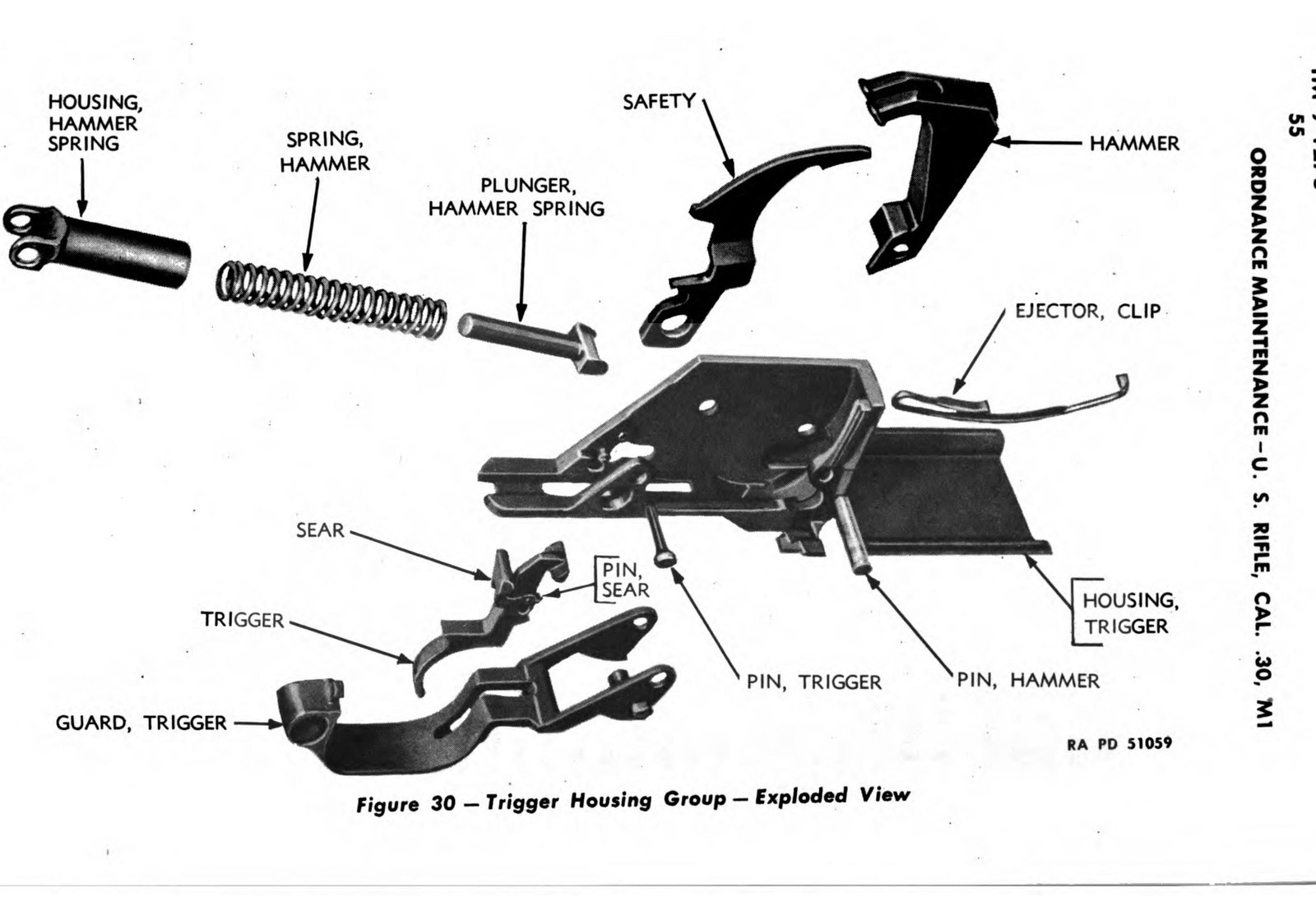
- The safety is inside the front of the trigger guard. Pushed back, it blocks the trigger and holds the hammer. The 1969 operator’s manual adds a check worth doing: the safety will not engage with the hammer forward.
- The trigger guard locks the group into the receiver. Its locking lugs wear; the ordnance fix was to peen them lightly and dress them (Vol 11).
- The hammer spring drives the hammer through a plunger in a housing. It exerts a lot of force, which is why the manuals tell you to support the trigger while drifting its pin.
- The clip ejector is the spring arm that throws the empty clip.
5.7 The Sights
The rear sight has two knobs. The left knob raises and lowers the aperture in one-minute clicks; the right knob moves it for windage, also one minute per click on a standard sight. National Match rear sights gave half-minute windage, and later hooded apertures half-minute elevation. The rear sight nut in the windage knob sets the tension that keeps the aperture from creeping under recoil; Vol 10 has the test. The range markings on the elevation knob are calibrated for Ball M2.
The front sight is a blade on the gas cylinder, held by a screw that on spline-type cylinders is sealed. The manuals tell soldiers not to remove or adjust it; zeroing is done with the rear sight.
Sources
- U.S. Army, FM 23-5, U.S. Rifle, Caliber .30, M1 (1965), cycle of operation and cautions.
- U.S. War Department, TM 9-1275, U.S. Rifle, Cal. .30, M1 (December 1941 and November 1942 editions).
- U.S. Army, TM 9-1005-222-12 (1969) and TM 9-1005-222-35 (1966).
- Garand Gear, “M1 Garand No-Fire” and inspection guides.
- m1-garand-rifle.com, “Gas Pressure.”
- Fulton Armory, “Everything you wanted to know about M1 Garand operating rods.”
- Fulton Armory, “How do I sight in my M1 Garand?”
Comments (0)