M1 Garand · Volume 10
Maintenance, Lubrication and Gauging

The M1 was designed to run dirty, and it will. It was not designed to run dry, and it was not designed to be cleaned with abrasives. Most of what an M1 needs is in two places the manuals are emphatic about — grease on the working surfaces, and nothing at all on the piston — and most of what you need to know about a used rifle is in four numbers: throat erosion, muzzle erosion, headspace and firing-pin protrusion.
This volume is the routine, and the gauging. Vol 11 is what to do when something is wrong.
10.1 Grease, and Where It Goes
The M1’s working surfaces take grease, not oil. The list of where changed from edition to edition, so here are the editions rather than a merged list:
Table 1 — The M1's working surfaces take grease, not oil. The list of where changed from edition to edition, so here are the editions rather than a merged list
| Manual | Lubricant | Where |
|---|---|---|
| FM 23-5 (1940) | “lubricating grease (U.S.A. Spec. SXS77),” in tubes | Bolt locking and operating lugs; bolt guides; cocking cam on the bolt; contact surfaces of barrel and operating rod; operating rod cam; operating rod guide groove in the receiver; operating rod spring |
| FM 23-5 (1951) | “rifle grease,” sparingly, “on those parts subject to heavy wear in wet climates” | Locking lugs, operating lug and recesses; bolt guides; cocking cam; barrel and rod contact surface; rod guide groove; rod spring; camming surfaces in the rod’s hump |
| FM 23-5 (1965) | rifle grease; oil at normal temperatures; cold-weather oil below 0°F | Lip of the receiver; locking recesses; bolt camming lug; camming surface in the hump of the operating rod (Figure 33) |
| TM 9-1005-222-12 (1969) | rifle grease, light coat | Locking lugs of the bolt, operating lug and recesses; bolt guide; cams on the trigger and hammer |
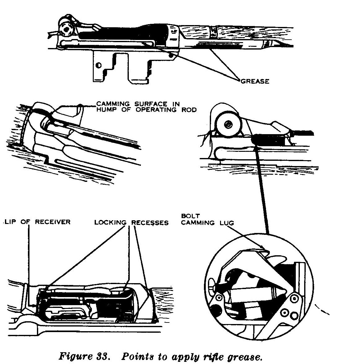
Two cautions the manuals give:
- Keep grease out of the chamber. The 1940 manual: “Do not apply lubricating grease to the follower slide or the under surface of the bolt, as the introduction of grease into the chamber may lead to the generation of excessive pressure.” And: “Never grease or oil the ammunition or the rifle chamber walls.”
- The trigger group: cams, not hooks. The 1969 manual greases the cams on the trigger and hammer. Collective armorer advice warns against grease on the hammer hooks and sear, where it can contribute to doubling. The two are not a contradiction — cams are not hooks — but be precise about which surfaces you are greasing.
The Army named its greases by specification: SXS77 in 1940, and later “grease, rifle,” stock number 9150-754-0063. The commercial greases shooters use now — Lubriplate and the like — are not named in any of the manuals consulted.
10.1.1 Nothing on the piston
The 1969 operator’s manual, verbatim:
“The use of abrasives, steel wool, wire brushes, or scrapers on the piston area of the operating rod assembly will change critical dimensions that may cause the weapon to malfunction and is therefore prohibited. The application of lubricants to this area is also prohibited.”
The 1965 field manual names the consequence: short recoil from an “undersized piston (caused by the use of abrasives when cleaning the piston).” The piston’s specification is at least 0.525 inch; Fulton Armory gives 0.525 to 0.526 inch, round within 0.00035 inch. A piston is an easy part to ruin with a wire brush.
10.2 Cleaning After Firing
10.2.1 The routine
From the 1969 operator’s manual:
- Immediately after firing, run a bore brush wet with bore cleaner through the bore, then dry patches until they come out clean, then a light coat of oil.
- Clean the chamber with the chamber brush dipped in cleaner.
- Clean every surface exposed to powder fouling — “bolt face, chamber, piston area of operating rod assembly and gas cylinder lock screw” — with cleaner. Bore cleaner “is not a lubricant.”
- Carbon: soak in carbon-removing compound for 2 to 16 hours, then brush under running water with a stiff bristle brush, not wire.
- Never use gasoline, kerosene, benzene, high-pressure water, steam or air.
The 1965 field manual adds the discipline: clean the rifle “no later than the evening of the day it is fired,” then check for fouling for three consecutive days, oiling the bore lightly after each check. And: “A muzzle plug should never be used … It causes moisture to collect in the bore.”
10.2.2 Two details that trip people up
- Use the M1 chamber brush. The 1965 manual: “The M14 rifle chamber brush is ⅛-inch shorter and will not clean the M1 chamber.”
- Hot soapy water is a fallback, not a method. The 1951 manual offered it as an alternative to bore cleaner; the 1965 manual says it “is no substitute for bore cleaner and will only be used when bore cleaner is not available.” For corrosive ammunition, water-based cleaning comes first on purpose — see below.
10.2.3 After corrosive ammunition
Pre-1952 American military .30-06 is corrosive (Vol 12 has the lot table). The primer residue is a salt that pulls moisture and rusts, and on an M1 it goes into the gas cylinder, the lock screw and the piston area, not just the bore.
The 1940 field manual is the primary guidance: hold the rifle “bottom side up, so that no water will enter the gas port” while cleaning the bore with wet patches and brush; for the chamber, “saturate a cleaning patch with cleaner, rifle bore, or with water, in order to dissolve any primer fouling”; then oil with the rifle “top side up, so that some of the oil will flow into the gas port.”
The sequence recommended here after corrosive surplus: a water-based cleaner through the bore, chamber, gas cylinder and lock screw first, to dissolve the salts; dry; then a normal solvent clean; then oil; then the three-day check.
10.2.4 Wood
The 1969 manual: rub raw linseed oil into the wooden parts periodically — with a caution: “Do not apply linseed oil to those surfaces next to the barrel. Application of oil to these surfaces creates heavy smoking when the barrel is hot.”
10.2.5 Storage and cold
- The 1940 manual (as changed in 1942) says the oil issued with the rifle protects the bore for one to two weeks with daily inspection, and a light rust-preventive compound for about a year; bare hands should not touch dried metal before the compound goes on.
- Below 0°F, the 1941 maintenance manual has the rifle cleaned completely with dry-cleaning solvent and run dry; above 0°F, lightly oiled. The 1965 manual adds: keep the rifle at outside temperature, so that condensation does not form when it comes in and goes out.
10.3 Gauging
10.3.1 Throat erosion
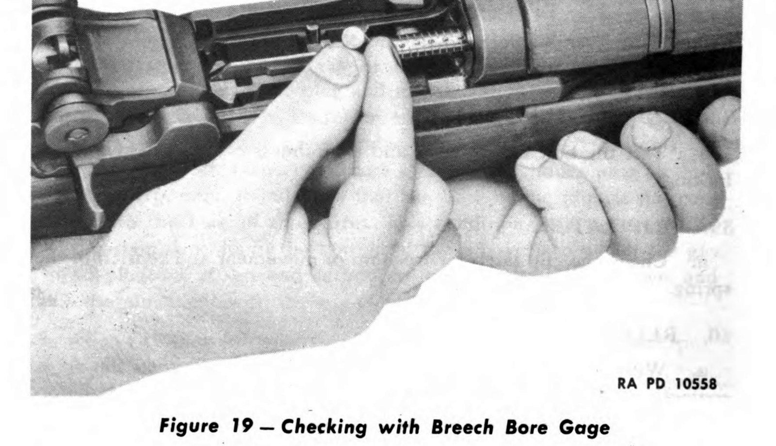
The breech bore gage measures how far the throat has worn. The 1941 maintenance manual describes it: “10 graduations, each of which corresponds to .001 inch of wear. The 10th graduation or point marked ‘reject’ is equivalent to a bore diameter of .310 inch as the zero graduation is .300 inch.”
- 0.310 inch or more: unserviceable (1942 manual).
- 0.306 inch: the maximum for overseas duty (1966 depot manual).
Modern commercial throat-erosion gauges read the same way, so a reading of 6 means about 0.306 inch. That has not been confirmed against a gauge maker’s instructions, so treat the conversion as close rather than exact.
10.3.2 Muzzle erosion
The muzzle-erosion gauge is a post-war armorer’s tool, and no primary definition of its scale was found in the wartime manuals. The practical meaning comes from the CMP’s grades, where lower is better and 2 or less is excellent. Muzzle wear is where cleaning-rod damage shows, which is a good reason to use a rod guide or pull-through and to be careful at the crown.
10.3.3 The CMP’s gauge thresholds
Table 2 — The CMP's gauge thresholds
| Grade | Throat erosion | Muzzle erosion |
|---|---|---|
| Collector | under 3 | 2 or less |
| Correct | less than 4 | 2 or less |
| Service | less than 5 | 3 or less |
| Field | less than 6 | may gauge 3 or more |
| Rack | may gauge more than 5 | may gauge more than 3 |
10.3.4 Barrel condition
The 1942 manual inspects the bore with a barrel reflector from muzzle to breech. A bulge — a shadowy depression or dark ring in the bore, often visible as a raised ring outside — means the barrel is scrap. Pitting is acceptable while the lands stay sharp and distinct; a barrel is scrap when pits break the lands or grooves enough to let gas past the bullet, and the manual gives the rule of thumb: “A pit the width of a land or groove and 3⁄8 to 1⁄2 inch long or longer indicates this condition.”
10.3.5 Headspace
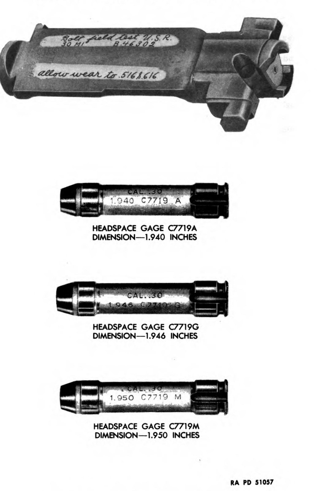
The Army’s M1 headspace gages:
Table 3 — The Army's M1 headspace gages
| Gage | 1941 manual | 1942 manual |
|---|---|---|
| Smallest | 1.942 inch (C7719C) | 1.940 inch (C7719A) |
| Middle | 1.946 inch (C7719G) | 1.946 inch |
| Largest | 1.950 inch (C7719M) | 1.950 inch |
How they were used, from the 1941 manual:
- In the field, with the 1.950 gage: “If the bolt will not close on the gage, the headspace is satisfactory.”
- At arsenal or depot, the bolt should not close on the 1.946 gage and should close freely on the smaller gage.
- The field test bolt told an inspector whether excess headspace was in the bolt or in the receiver.
Do not compare these numbers with commercial .30-06 figures. The SAAMI .30-06 headspace dimensions run from about 2.049 to 2.059 inches. The Ordnance gages measure to a different reference point — a 0.1-inch difference is not a tolerance — and what that reference was has not been established. Use a commercial GO / NO-GO / FIELD set on a rifle today, and read them as SAAMI numbers. The headspace dive in this collection covers gauges, feeler stacks and measuring an actual figure.
10.3.6 Firing-pin protrusion
The 1966 depot manual’s gage: 0.044 to 0.060 inch. The 1941 manual gave a looser 0.030–0.065 for the fired position.
10.3.7 Trigger pull
The specification moved:
Table 4 — The specification moved
| Source | Service rifles | Rebuilt |
|---|---|---|
| TM 9-1275, December 1941 | more than 3½ lb, no more than 7½ lb | at least 4½ lb |
| TM 9-1275, November 1942 | more than 5 lb, no more than 7½ lb | at least 5½ lb |
| FM 23-5, 1965 | 5½ to 7½ lb | — |
| TM 9-1005-222-35, 1966 | 5.5 to 7.5 lb (M1C and M1D: 4.5 to 6.5 lb) | — |
| National Match conditioning | 4 lb 8 oz to 6 lb | — |
The CMP’s as-issued match rules require at least 4.5 pounds.
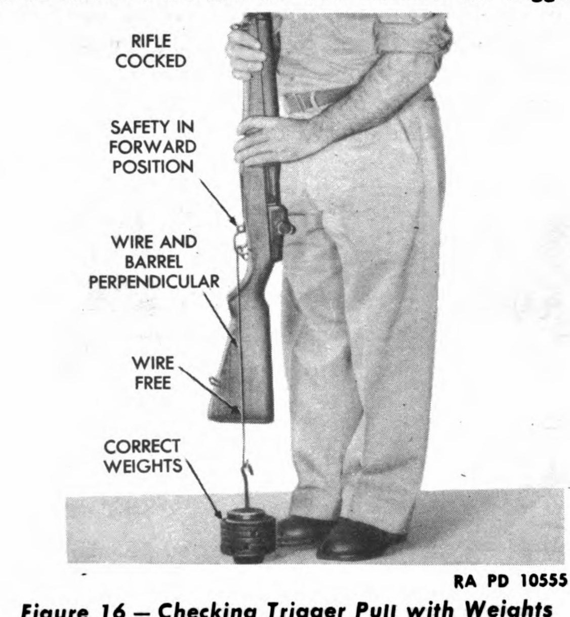
The 1942 manual adds that the trigger should move “to the rear without stopping or gritting.”
10.3.8 Springs
Operating rod spring free length is one of the specifications sources genuinely disagree about:
Table 5 — Operating rod spring free length is one of the specifications sources genuinely disagree about
| Source | Figure |
|---|---|
| TM 9-1275 (1941) | 20.0 inches maximum for the later spring; 19.5 for the early type |
| Springfield Armory drawing, via Nicolaus Associates | 20.25 inches maximum |
| Nicolaus Associates’ test with the 1947 manual’s weights | 19.00 inches minimum |
Garand Gear’s point is the useful one: length alone “doesn’t tell us if the spring constant has changed.” A spring of doubtful age is cheap; replace it rather than measure it.
10.3.9 Gas cylinder and piston
- Piston: 0.525 to 0.526 inch (above).
- Gas cylinder bore, by Garand Gear’s pin-gauge method: a 0.528-inch pin should pass the full length; a 0.532-inch pin should stop just past the threads. If the 0.532 pin goes in more than half an inch, the cylinder is at the end of its life.
10.3.10 Rear sight tension
The test, from the 1965 field manual: raise the aperture to full height, lower it two clicks, grip the small of the stock, and press down on the aperture with your thumb. “If the aperture drops, sight tension must be adjusted.” (The 1969 manual says to lower it four clicks instead — same test, different starting point.)
To adjust: with the screwdriver end of the cleaning rod handle, turn the windage knob nut clockwise if too loose, counter-clockwise if too tight, one click at a time, and test again.
10.3.11 Receiver and bolt
- Receiver heel: look for cracks. Garand Gear’s test: saturate the area with kerosene or mineral spirits, wipe it quickly, and a crack weeps a glossy line.
- Bolt lugs: both should show contact wear. Look for cracks or chips.
- Operating rod straightness: sighted from the top, the rod should look straight; from the side, its two bends should show. The tilt test: with the rifle tilted about 60 degrees, the bolt and rod should open and close under their own weight without binding. Never straighten a rod yourself (Vol 11).
10.4 A Maintenance Schedule
This schedule is not taken from any one manual; it is built from them:
After every range day
- Bore, chamber, bolt face, gas cylinder lock screw and piston area cleaned; three-day check.
- Grease the lugs, recesses, bolt camming lug and rod hump.
- Function check (Vol 8).
Every few hundred rounds, or yearly
- Full field strip and clean, including the gas cylinder.
- Rear sight tension test.
- Tilt test for the operating rod.
On acquiring a rifle, and then occasionally
- Throat and muzzle erosion.
- Headspace, with commercial gauges.
- Firing-pin protrusion.
- Trigger pull.
- Operating rod spring replaced if its history is unknown.
- Receiver heel crack check.
Sources
- U.S. War Department and Department of the Army, FM 23-5 (1940, 1951 and 1965 editions).
- U.S. War Department, TM 9-1275 (December 1941 and November 1942).
- U.S. Army, TM 9-1005-222-12 (1969), paragraphs 3-6 and 3-11 and Tables 3-2 to 3-5.
- U.S. Department of the Army, TM 9-1005-222-35 (1966), Table 3-1.
- Civilian Marksmanship Program, M1 Garand grades, checked September 14, 2026; CMP Games Rules (2025).
- Fulton Armory, operating rod article.
- Garand Gear, “M1 Garand Inspection.”
- Nicolaus Associates, “M1 Garand Operating Rod Spring Length.”
- Bruce N. Canfield, “The National Match M1 Garand,” American Rifleman.
- ANSI/SAAMI Z299.4-2015.
Comments (0)