CRT Timing · Volume 7
What Does and Does Not Work — Rescuing CRT Guns on Modern Displays
Keeping a tube, flash-frame play on a lagging LCD and what it costs, why a beam-racing CRT simulator on a 480 Hz OLED cannot bring back a latch gun, what a display would need to, and the coded-frame idea that generalises the Zapper
7.1 Two different questions
“Can a CRT light gun work on a modern display?” is two questions. One is about the old guns and old games: can a Zapper, a Super Scope or a GunCon be made to work, unmodified or nearly so, with a television that is not a CRT? The other is about the method: could a new gun, built today, use screen timing instead of a camera? This volume answers both from the requirements of Volume 6 and the evidence that has been published. The short answers are: for flash-frame guns and games, partly, with a modified gun and a patched game; for latch guns, no; for a new build, the method’s one surviving form is a structured-light idea nobody has published as a light gun.
The practical side of conversions, which parts to buy and how to modify a classic gun, belongs to Modding Classic Light Guns. The platform side, which systems still drive a real CRT, belongs to MiSTer FPGA and Original Consoles.
7.2 Keep a direct-drive CRT
Every CRT gun works on a direct-drive CRT, because such a tube meets all four requirements by construction (Volume 6, §6.1). The qualifications are the ones Volume 6 sets out:
- Direct drive. No 100 Hz processing, no line doubler, no digital “picture enhancement” in the path. Many late CRT sets digitised their input, and those are not direct-drive.
- The source must produce real raster timing. An original console does. A modern source works only if it generates an analogue raster in real time with the console’s line timing and with the gun’s latch tied to the same counters that generate that raster. An FPGA reimplementation can, in principle, do this exactly, because it can generate the video and latch the gun from the same clock. A software emulator outputting through a frame buffer cannot guarantee microsecond alignment between the light the gun sees and the counter it latches. Which platforms achieve this is a question for MiSTer FPGA.
- The phosphor and the picture must suit the gun. Blue-green, bright targets (Volume 2).
7.3 Flash-frame on a lagging display
The flash-frame method needs only frame-level timing, so it is the one that can survive. Volume 4, §4.7, lists what it needs: a sensor that sees a non-scanning display, a program that waits out the display’s lag, and frames that arrive intact. Each one has a cost that can be put in numbers.
The sensor. A line-rate band-pass sees nothing from an LCD, so the sensor must respond to slow changes, down to DC, and reject room light by some other means. Modern Mallard’s replacement Zapper board (2018) did exactly that: a photodiode, transimpedance amplifier and a gain stage with servo, sampled by a PIC16F18313 microcontroller’s ADC, with logic to reject fluorescent and LED room light, and an adaptive slicer that needs about 64 ms of looking at the screen before a shot.1 The NESdev wiki notes that some clone Zappers already have “a much weaker filter that responds more readily to these slower changing light sources”.2 Either way, the band-pass that made the original Zapper lamp-proof is gone, and the check frame (Volume 4, §4.6) becomes the main defence.
The lag. If the display shows each frame L frames late, and the program pipelines its test frames (draws them back to back without waiting for each answer), the answers arrive in order L frames later. A shot with N targets then costs L + N + 1 frames instead of N + 1. With the “16 to 100 ms” of lag the Modern Mallard designer gives for typical LCD sets,1 L is 1 to 6 frames, so a two-target shot takes 4 to 9 frames, 67 to 150 ms, from trigger to answer. The program must know L, which is why Modern Mallard has the player shoot the menu screen once to calibrate it.1
The pixel response. The test box must be bright enough, for long enough, for the sensor to see it. Elze measured LCD rise times of 5 to 17 ms on two monitors,3 which at 16.7 ms a frame means a one-frame box may barely reach full brightness before the next frame begins to dim it. A flash-frame game on an LCD may need to hold each test box for two frames, doubling N’s cost, or the sensor’s threshold must be set low enough to catch a partly risen box, which weakens its rejection of everything else.
Intact frames. Frame interpolation or “motion smoothing” synthesises frames between the ones sent, and blends the black check frame with the picture on either side. A set’s game mode, which normally disables that processing and also reduces lag, is a requirement, not an option.
A patched game. None of this works with the original Duck Hunt: its code expects the answer in the frame the box was drawn. Modern Mallard rewrote the shot and hit-detection code through a bus-intercept board using an NXP Cortex-M4 that substitutes patched data on the NES’s bus.1 The NESdev wiki likewise pairs a weak-filter clone with “a software patch to compensate for the display lag delay”.2
The evidence that the whole package works is one 2018 project, whose Kickstarter “failed to get funded” and which states that “no kits are for sale at this time”.4 It is good evidence that the method can be rescued; it is not a product anyone can buy.
7.4 Latch guns on a beam-racing CRT simulator
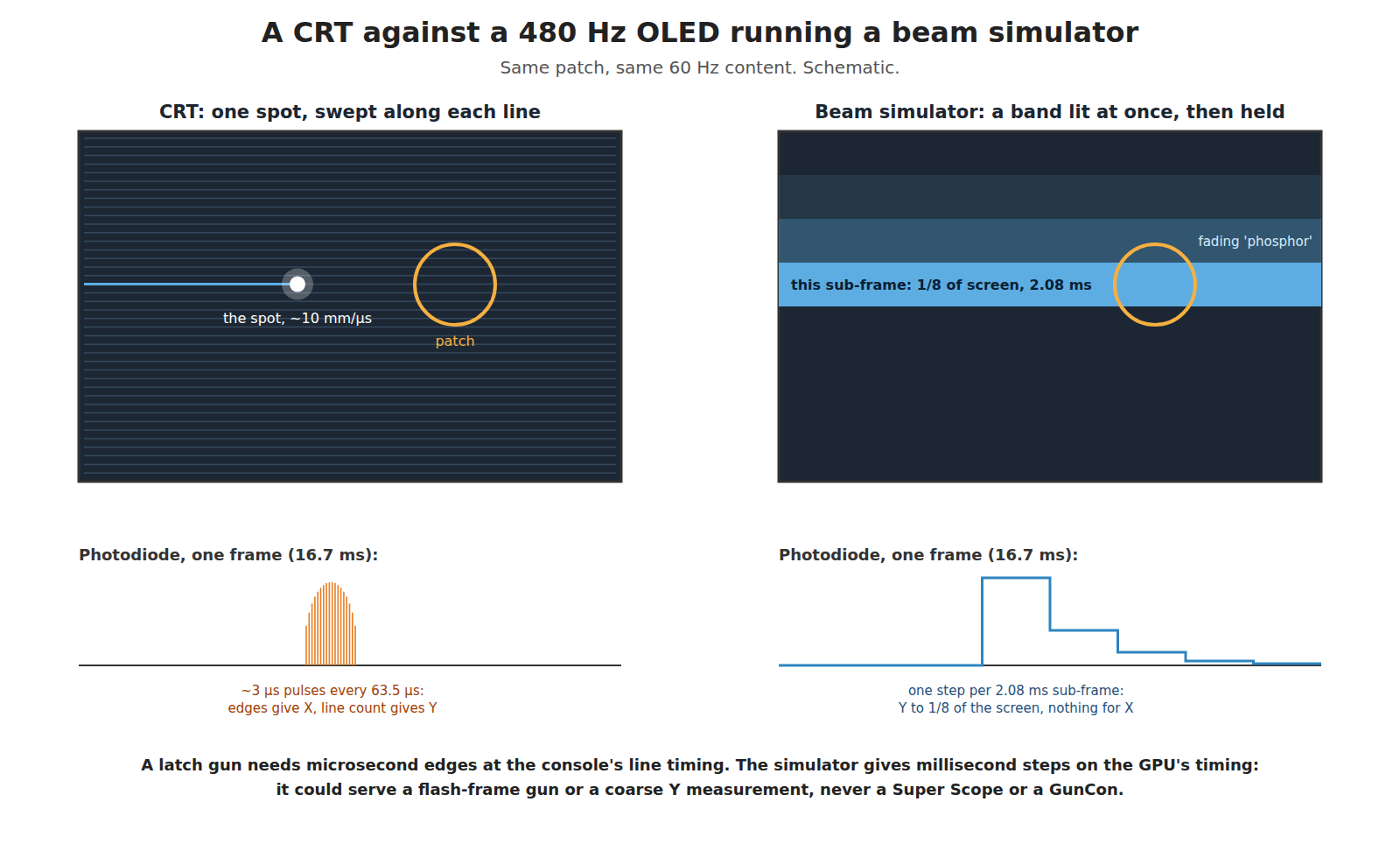
Fast OLED monitors have revived interest in imitating a CRT’s scan. Blur Busters’ CRT Beam Simulator, by Mark Rejhon and Timothy Lottes (originally 2022, published 2024, MIT licence), is a shader that draws each 60 Hz frame as several sub-frames on a high-refresh display, lighting a band that rolls down the screen with simulated “phosphor fadebehind”. Its source recommends four sub-frames per frame at 240 Hz and eight at 480 Hz, and its README claims up to 87.5 % less motion blur for 60 fps content on a 480 Hz display.5 It exists to reduce motion blur, and nothing in its documentation mentions light guns. No published test of a CRT light gun on it, or on any rolling-scan display, was found.
Score it against the four requirements, at its best setting, 480 Hz:
Table 1 — Score it against the four requirements, at its best setting, 480 Hz
| Beam simulator at 480 Hz, eight sub-frames per 60 Hz frame | |
|---|---|
| R1, line-rate pulses | No. Light changes in steps of one sub-frame, 2.08 ms. Within a sub-frame, a band about one-eighth of the screen, about 30 lines of a 240p picture, is lit at once and held. There is no 15.7 kHz content. |
| R2, fixed time after the console’s sync | No. Sub-frame timing is set by the GPU and the panel’s own scan-out, after the emulator’s frame buffer. |
| R3, console’s order and rate | Partly, in the vertical: the band moves down the screen in order, one-eighth at a time. Not at all in the horizontal: a panel writes a whole row at once, so there is no left-to-right sweep within a line. |
| R4, frames intact | Yes, if the pipeline holds its timing; late by the system’s latency. |
So a latch gun aimed at such a screen sees, at best, a light that steps up when the band reaches its patch and fades over the following sub-frames. That is a timing signal with a resolution of one band, about 30 lines vertically, and no horizontal information whatever. No calibration can supply what the display does not emit. A beam-racing simulator could, in principle, serve a gun that measures Y to an eighth of the screen, or a flash-frame gun; it cannot serve a Super Scope or a GunCon.
7.5 What a display would need
Turning the requirements into a display specification shows how far the best panels are from serving a latch gun.
Table 2 — 7.5 What a display would need
| To imitate | A display would need | Today’s figure in the sources read |
|---|---|---|
| The line sequence (R3 vertical) | to light one 240p line at a time, so 15,734 “sub-frames” per second | 480 Hz recommended by Blur Busters for 60 Hz content; “960Hz better than 480Hz”5 |
| The sweep along a line (R3 horizontal, R2) | to light each column in turn, at the console’s dot rate, 5.37 million columns per second, each lit for ~186 ns | no panel addresses columns sequentially; rows are written whole |
| Phosphor-like pulses (R1) | emission that rises and falls within about a microsecond after each column is “struck” | sample-and-hold within a refresh, by design5 |
| A fixed time to sync (R2) | a path from console to light with variation under 1 µs | lag “between 16 and 100 ms” for typical LCD televisions, with no stated variation1 |
The first row alone is a factor of 33 beyond a 480 Hz panel. The second is not a question of refresh rate at all: it needs a display whose pixels can be lit one column at a time in a raster sweep, which is what an electron beam does and what a matrix panel is built not to do. A display that met all four would be, functionally, a CRT. This is the arithmetic behind the conclusion of History of Light Guns, Volume 6 that timing guns could not be patched.
7.6 Coded frames: the Zapper method generalised
The flash-frame method survives because it asks a frame-level question. It can be generalised from “is the gun on target k?” to “where is the gun?” by drawing coded frames: a sequence of black-and-white patterns whose on/off history at each point of the screen is unique. With binary or Gray-code stripes, log2 of the screen width in frames resolves X and the same for Y; a 1,920 × 1,080 screen needs 11 frames for X and 11 for Y. This is the structured-light technique of 3-D scanners, applied with a single photodiode instead of a camera.
Table 3 — 7.6 Coded frames: the Zapper method generalised
| Display | Frames per shot (X and Y, full HD) | Time per shot | Flicker the player sees |
|---|---|---|---|
| 60 Hz | 22 + lag | about 370 ms + lag | severe |
| 240 Hz | 22 + lag | about 92 ms + lag | visible |
| 480 Hz | 22 + lag | about 46 ms + lag | brief |
Resolution can be traded against time: 8 frames per axis give 256 positions, an eight-pixel step on a 1,920-pixel screen, in 16 frames, 33 ms at 480 Hz. The sensor is the DC-coupled one of §7.3, and the lag problem is the flash-frame one, absorbed by pipelining and a calibration shot.
This is an idea, not a finding: no published light gun using coded frames was found in the sources read, and it was not tested. It gives up the CRT gun’s best property, invisibility to the player except for a brief flash, in exchange for working on any display. Whether that trade is worth anything when a camera gun works without flashing the screen at all is a question for Experimental Sensing, where it belongs with the other unbuilt ideas.
7.7 What carries over to a camera gun
The build this category follows uses a camera and infrared emitters, not screen timing (IR Point Tracking, Reference Electronics). Three lessons from this dive carry over unchanged:
- Fixed delays are free; variable ones cost. A camera gun’s latency (exposure, readout, processing, USB, the game, the television) is long, but only its variation makes the cursor wander. Measuring the spread matters more than measuring the mean. The latency budget is in Aiming Maths and Calibration.
- Calibrate from where you play. The CRT gun’s range-dependent patch offset (Volume 5, §5.5) and sight-line parallax have direct counterparts in a camera gun’s geometry.
- Reject the room by what the signal is, not by how bright it is. The CRT gun’s line-rate filter is the ancestor of a camera gun’s infrared filter and blob tracking: both decide what is the screen by a property lamps do not have.
7.8 What could not be verified
- Any published test of a CRT light gun on a rolling-scan or beam-simulating display.
- Any published light gun using coded or structured-light frames.
- Which FPGA or emulator platforms deliver microsecond-aligned raster timing to a real CRT with a latch gun; that is left to the platform dives.
- Television lag figures beyond one designer’s range.
Sources
Footnotes
-
Teuobk, “Modern Mallard: a kit to make the NES game Duck Hunt work on an LCD TV”, EEVblog forum, 28 June 2018, https://www.eevblog.com/forum/crowd-funded-projects/modern-mallard-a-kit-to-make-the-nes-game-duck-hunt-work-on-an-lcd-tv/, read 2026-10-19. ↩ ↩2 ↩3 ↩4 ↩5
-
NESdev Wiki, “Zapper”, https://www.nesdev.org/wiki/Zapper, read 2026-10-19 via the Internet Archive. ↩ ↩2
-
Tobias Elze, “Achieving precise display timing in visual neuroscience experiments”, Journal of Neuroscience Methods 191 (2010) 171–179, read 2026-10-19. ↩
-
Modern Mallard, https://www.modernmallard.com/ (© 2018 Metsasta LLC), read 2026-10-19. ↩
-
Mark Rejhon and Timothy Lottes, Blur Busters CRT Beam Simulator, README and
crt-simulator.glslheader comments (MIT licence; header dated December 2025), https://github.com/blurbusters/crt-beam-simulator, read 2026-10-19. ↩ ↩2 ↩3
Comments (0)