CRT Timing · Volume 6
What Breaks It — Interlace, 100 Hz Sets, Line Doublers, LCD and OLED
The four things a CRT gun needs from a display, and which of them each later display takes away: 480i's half-line offset, field memories and doubled line rates, sample-and-hold panels, scaler lag, and why no calibration can bridge the gap
6.1 Four things a CRT gun needs
History of Light Guns, Volume 6 tells how the flat panel ended the CRT gun and explains, at signal level, the three things an LCD takes away. This volume generalises it. From Volumes 1 to 5, a CRT gun depends on four properties of the display, and each later display can be scored against them:
Table 1 — [History of Light Guns, Volume 6](/light-guns/history-and-hardware/history-of-light-guns/vol-6/) tells how the flat panel ended the CRT gun and explains, at signal level, the three things an LCD takes away. This volume generalises it. From Volumes 1 to 5, a CRT gun depends on four properties of the display, and each later display can be scored against them
| Requirement | Needed by | |
|---|---|---|
| R1 | Light from a patch arrives as short pulses at the line rate, one per line crossing the patch | the Zapper’s band-pass (Volume 3); every latch gun’s edge |
| R2 | Each pulse arrives at a fixed time after the console’s own sync for that line, to within about a microsecond | every latch gun (Volume 5) |
| R3 | The display draws the console’s lines in the console’s order and at the console’s rate | the line count for Y; the H counter’s meaning for X |
| R4 | Each frame the console sends is shown once, intact, in the frame the program expects | the Zapper’s test frames (Volume 4) |
A direct-drive CRT meets all four by construction: its deflection is locked to the console’s sync pulses, and nothing is stored (Volume 1, §1.2). Everything below is a failure of one or more.
6.2 Interlace: 480i and 576i
Interlaced video meets all four requirements. It changes what the numbers mean.
In broadcast NTSC each field is 262.5 lines, and the half line puts the second field’s lines halfway between the first’s (Volume 1, §1.3). The console’s vertical counter counts lines within the field. fullsnes notes that the Super NES’s V counter runs 0 to 261 normally and reaches 262 “every other frame when interlace is active”, and that bit 7 of $213F reports the current interlace field.1 So:
- X is unaffected. The line rate, the dot clock and the latch all behave as in 240p.
- Y is a field line, with a half-line ambiguity. Line k of the second field lies between lines k and k + 1 of the first. A game that wants 480-line vertical resolution must read the field bit and combine it with the line count. One that does not gets 240-line resolution, which for a light gun is no loss at all: the patch is 20 lines across, and the vertical error is dominated by which line of the patch latches (Volume 5, §5.6).
- Thin targets flicker for the gun. A detail one 480-line row high is drawn in only one field of each pair, so its patch is lit 30 times a second instead of 60. To a latch gun that means one shot in two sees nothing there. Targets should be at least two rows high.
- The burst is the same size. Each field still draws about 240 lines spread over the whole height, so a patch of a given size crosses the same number of lines per field as in 240p.
On the bench, a sync separator’s odd/even output identifies the field. TI’s LM1881 and LMH1980 both provide one (Volume 3, §3.9).23
6.3 100 Hz sets: the field memory
In the 1990s European manufacturers sold CRT televisions that displayed 50 Hz PAL at 100 Hz to remove large-area flicker. The technique is a field memory. A 1981 Philips patent, US 4,435,728 (Raven and Annegarn, filed in the Netherlands in February 1981), describes the classic circuit: two field memories, one written with the incoming field while the other is read out at twice the rate, and its drawing shows incoming fields A1 B1 A2 B2 leaving as A1 A1 B1 B1 A2 A2.4 Later sets did the same in a single chip; Philips’s SAA4979 is described in a 2002 conference paper as a one-chip 50/60 to 100/120 Hz converter with its memory built in.5
Score it against the four requirements:
Table 2 — Score it against the four requirements
| 100 Hz set with a field memory | |
|---|---|
| R1, line-rate pulses | Changed. Each field is drawn in 10 ms, so the line rate is doubled, to about 31.25 kHz. A Zapper’s filter, which responds from roughly 13.5 to 20 kHz (History of Light Guns, Volume 3), sits below it. |
| R2, fixed time after the console’s sync | Lost. What reaches the tube is read from memory on the set’s own timebase, after a delay of a large part of a field. The tube’s lines no longer begin when the console’s do. |
| R3, console’s order and rate | Lost. Each console line is drawn at half its duration, and each field twice. |
| R4, each frame once and in time | Lost. Each field is shown twice, 10 ms apart, later than it was sent; some designs interpolate an in-between field instead of repeating. |
A latch gun on such a set still sees short pulses at a line rate, and may well latch. What it latches is the console’s counter at the moment the set’s beam passed, a moment set by the memory’s read clock, so the coordinate it reports has no fixed relationship with where it points, and two different answers arrive per console frame. That is consistent with Namco’s own instructions. The European Time Crisis manual, as recorded in Console Light Guns, Volume 4, says the G-CON45 cannot be used with 100 Hz televisions or televisions with a screen-memory function, along with LCD sets, projectors and projection televisions.6 Owners’ forum reports say the same, one describing the crosshair flying repeatedly across the screen; those are user reports, not tests, and are cited only as such.7
The European releases of some later games reportedly included a hidden 100 Hz option in their calibration screen.7 Nothing read for this dive says what it changed, and it was not verified.
6.4 Line doublers and 31 kHz
A line doubler or scan converter shows 15 kHz video on a 31 kHz progressive display (a VGA monitor, a “progressive scan” CRT television, or the input stage of many flat panels). It stores at least one line, often a field, and draws each stored line twice at double the rate. The NESdev wiki records that “some high-definition displays and upscalers cannot handle 240p video, instead introducing artifacts that make the video appear as if it were interlaced”.8
On a 31 kHz CRT fed by a line doubler, R1 survives in a doubled form (short pulses at 31.5 kHz), but R2 and R3 fail for the same reasons as in §6.3. The output line takes 31.8 µs instead of 63.5 µs, so if the latch fired on the doubled raster, the time from the console’s horizontal sync to the light would map onto the screen at half the scale, offset by the converter’s delay, and alternating between the two copies of each line. A gun calibrated on such a display could at best be made to work at one range, at one position, with one converter; in practice nothing about the converter’s delay is guaranteed to be constant. The point to take away is that a CRT is a light-gun display only when it is driven directly. A tube behind a frame or line memory is, for a light gun, no better than a flat panel.
6.5 LCD: sample and hold
Elze’s neuroscience measurements describe the LCD’s light output in the terms that matter here. LCDs are “sample and hold displays”, with no phosphors, “passively lit by a steady backlight”; a pixel’s luminance changes only as fast as the liquid crystal realigns; his measured rise times for two monitors “vary between 5 ms and 17 ms”; and the backlight is pulse-width modulated, with “typical dominant frequency values for the backlight” in his measurements ranging “between 160 Hz and 200 Hz”.9
Table 3 — 6.5 LCD: sample and hold
| LCD | |
|---|---|
| R1 | Lost. A patch stays lit for the whole frame; its light changes over milliseconds when the picture changes. The only fast modulation is the backlight’s PWM, at a few hundred hertz in Elze’s monitors, unrelated to the console and far from 15.7 kHz. A Zapper’s filter passes nothing. |
| R2 | Lost. The panel’s rows are written at the panel’s own timing, after the set has digitised, scaled and processed the frame. |
| R3 | Lost. A 240-line console frame is scaled to the panel’s row count; console line k is spread over a non-integer number of panel rows written at a different rate. |
| R4 | Weakened. Frames arrive late, by the set’s processing delay. Some sets add frame interpolation or blending, which mixes test frames with their neighbours. |
The panel does write its rows in sequence, top to bottom, so there is a scan of a kind, and a fast sensor can see a change sweep down the screen. But a row, once written, holds its light until the next write, a whole frame later, and the light changes over milliseconds. There is no short pulse at a line rate, and no edge with microsecond meaning. That is why a Super Scope reports “null”, “a valid raster signal could not be found”, in Nintendo’s words, and a GunCon reports no light.1011
6.6 OLED: fast pixels, still held
An OLED panel emits its own light, pixel by pixel, and its pixels change state far faster than liquid crystal; no figure was read for this dive. It does not change the score. An OLED is still driven from a frame buffer at the panel’s own timing, a row at a time, and within a refresh each row holds its level. Blur Busters’ CRT-simulator shader is explicit that it is “designed for sample & hold displays with excess refresh rate (LCDs and OLEDs)”.12 A fast pixel makes the sweep of rows sharper. It does not make a row emit a microsecond pulse when the console’s beam would have been there, and it does not remove the processing delay. R1 to R3 fail as for an LCD; R4 depends on the set’s processing.
Whether a fast OLED at a high refresh rate, driven to imitate a scanning beam, can bring a CRT gun back is a separate question, and Volume 7 works it through.
6.7 The arithmetic of lag
The gap between what a latch gun needs and what a flat panel gives is not a matter of degree. Using the only dated figure in the sources read for television lag, Modern Mallard’s designer’s “somewhere between 16 and 100 ms” for typical LCD sets:13
Table 4 — 6.7 The arithmetic of lag
| Quantity | Value |
|---|---|
| Timing a latch gun can tolerate, as variation | about 1 µs (Volume 5, §5.8) |
| Display delay, typical LCD television | 16,000 to 100,000 µs |
| Ratio | 4 to 5 orders of magnitude |
| Variation in that delay between sets and picture modes | itself thousands of µs |
A calibration shot subtracts a constant. To calibrate a latch gun to an LCD, the LCD’s delay would have to be constant to within a microsecond from shot to shot, and its panel rows would have to be written at the console’s line rate in the console’s order. Neither is true of any television, and neither is something a gun or a game can change. For the flash-frame method the same lag is merely a wait of one to six frames (Volume 4, §4.7). That asymmetry is the whole story of Volume 7.
6.8 All of it on one page
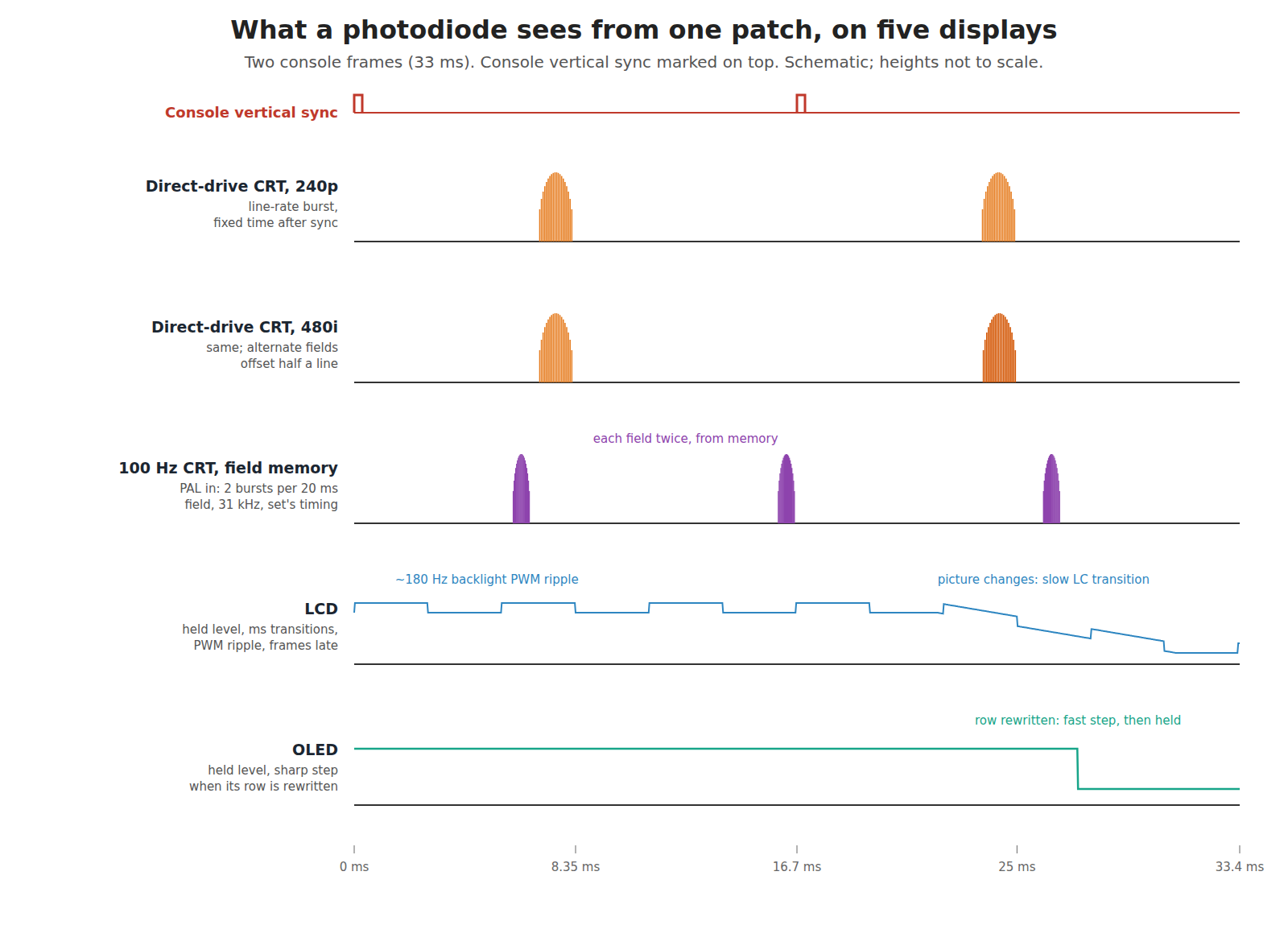
Table 5 — 6.8 All of it on one page
| Display | R1 line-rate pulses | R2 fixed time to console sync | R3 console’s order and rate | R4 frames intact, on time | Zapper (flash-frame) | Latch guns | GunCon (in-gun timing) |
|---|---|---|---|---|---|---|---|
| Direct-drive CRT, 240p | yes | yes | yes | yes | works | works | works |
| Direct-drive CRT, 480i/576i | yes | yes | yes, half-line offset | yes | works | works; Y per field | works |
| CRT with field memory (100 Hz) | doubled rate | no | no | no | fails (filter) | wrong coordinates | wrong coordinates |
| CRT behind a line doubler | doubled rate | no | no | delayed | fails (filter) | wrong coordinates | wrong coordinates |
| LCD | no | no | no | late, sometimes altered | fails; works with a DC sensor and a lag patch | fails | fails |
| OLED | no | no | no | late | as LCD | fails | fails |
The GunCon column is worth a second look. Because it times from the composite video’s sync rather than from the console’s chip, people sometimes expect it to survive a processed display. It does not, because its reference is the signal the console sends, while what it measures is the light the display emits; any display that stores and re-times the picture breaks the link between the two, whichever end the counter sits at.
6.9 What could not be verified
- The line rate and delay of any particular 100 Hz set; the analysis uses the field-doubling architecture of the Philips patent.
- What the hidden 100 Hz option in some PAL calibration screens actually did.
- OLED pixel response times; no measurement was read.
- Typical television input lag beyond the one designer’s figure; no primary measurement source was read, as History of Light Guns, Volume 6 also records.
- The SAA4979 description is from a conference abstract seen in search, not a Philips datasheet.
Sources
Footnotes
-
Martin Korth (nocash), fullsnes, “SNES PPU Timers and Status” (OPVCT ranges; STAT78 bit 7), https://problemkaputt.de/fullsnes.htm, read 2026-10-19. ↩
-
Texas Instruments, LM1881 datasheet, SNLS384G (revised June 2015), odd/even field output, https://www.ti.com/lit/ds/symlink/lm1881.pdf, read 2026-10-19. ↩
-
Texas Instruments, LMH1980 product page, https://www.ti.com/product/LMH1980, read 2026-10-19. ↩
-
Johannes G. Raven and Marcellinus J. J. C. Annegarn (U.S. Philips Corporation), “Field frequency-doubling circuit for a television signal”, US Patent 4,435,728, filed 18 January 1982 (Netherlands priority 9 February 1981), granted 6 March 1984, abstract and Fig. 2, USPTO full text read by OCR 2026-10-19. ↩
-
Conference paper on the Philips SAA4979 scan converter, IIC-China/ESC-China 2002 proceedings, p. 267, seen as a search excerpt only (https://varjukass.ee/Kooli_asjad/Ylikool/telekom/motion.pdf), 2026-10-19. ↩
-
Namco / Sony Computer Entertainment Europe, Time Crisis (PlayStation, PAL) instruction manual, G-CON45 sections, as read and quoted in Console Light Guns, Volume 4; scan at https://archive.org/details/18082024-002. ↩
-
User reports, not tests: shmups.system11.org forum, “Light gun games compatibility”, page 2, https://shmups.system11.org/viewtopic.php?t=65327&start=30; ASSEMBLERgames forum threads on PlayStation light guns. Read via search 2026-10-19. ↩ ↩2
-
NESdev Wiki, “NTSC video”, https://www.nesdev.org/wiki/NTSC_video, read 2026-10-19 via the Internet Archive. ↩
-
Tobias Elze, “Achieving precise display timing in visual neuroscience experiments”, Journal of Neuroscience Methods 191 (2010) 171–179, pp. 172–174, read 2026-10-19. ↩
-
Nintendo of America, Super NES Development Manual, Book II, Section 4, “Super NES Super Scope”. Internet Archive item
SNESDevManual, read 2026-10-19. ↩ -
Martin Korth (nocash), psx-spx, “Controllers — Lightguns — Namco (GunCon)”, https://psx-spx.consoledev.net/controllersandmemorycards/, read 2026-10-19. ↩
-
Mark Rejhon and Timothy Lottes, Blur Busters CRT Beam Simulator,
crt-simulator.glslheader comments (MIT licence; “Original Version 2022. Publicly Released 2024”), https://github.com/blurbusters/crt-beam-simulator, read 2026-10-19. ↩ -
Teuobk, “Modern Mallard: a kit to make the NES game Duck Hunt work on an LCD TV”, EEVblog forum, 28 June 2018, read 2026-10-19. ↩
Comments (0)