CRT Timing · Volume 5
Raster Latching — Counters, Latches and the Jitter Budget
What each console freezes and in what units, quantisation, every delay between phosphor and counter sorted into fixed and variable, the left-edge bias and the Menacer's eighth-line trick, the PlayStation's software latch, and a budget that reproduces Nintendo's eight-dot figure
5.1 What gets latched
A video chip already counts the beam. It needs a horizontal counter, clocked once per dot, to know when to fetch and output each pixel and when to emit sync, and a vertical counter, stepped once per line, to know which line it is drawing. A light-gun latch is a register that copies those counters at the moment an external edge arrives, so the program can read where the beam was when the gun saw it. Home-Computer Light Guns, Volume 1 gives the history and quotes Atari’s 1980 manual describing the first one, ANTIC’s PENH and PENV; its Volume 6 compares seven home-computer latches side by side. This volume covers the consoles and then treats the latch as a measuring instrument with an error budget.
Three properties of any latch decide what it can measure:
- Units. What one count of the horizontal value is worth in time, and therefore on the glass.
- Edge and re-arming. Which edge fires it, and whether it takes the first edge in a frame, every edge, or the edge after the program re-arms it.
- Where the timing reference comes from. Inside the chip that generates the sync (every console latch) or outside it (the GunCon, which separates sync from the video itself).
5.2 The consoles’ latches
Table 1 — 5.2 The consoles' latches
| Console and gun | Counter, units | Fires on | Re-arms | Source |
|---|---|---|---|---|
| Super NES: Super Scope, Justifier | OPHCT 0–339 dots (22–277 visible), 186 ns per count; OPVCT 0–261 lines (0–311 PAL) | “Lightgun High-to-Low transition (Pin6 of 2nd Controller connector)”, only while WRIO bit 7 is set | latch flag in $213F bit 6, reset by reading $213F | fullsnes1 |
| Master System: Light Phaser | 9-bit H counter, upper 8 bits readable, so 2 dots per count (~372 ns); V counter read freely by the program | TH line change on either controller port | ”remains frozen until TH is changed again” | MacDonald, SMS Power23 |
| Mega Drive: Menacer, Justifier | HV counter: VC7–VC0 lines and HC8–HC1, 2 pixels per count | TH, when VDP register 0 bit 1 is set; an I/O control bit plus register 11 can also raise a level-2 interrupt | not established by MacDonald (“I don’t know if the HV counter resumes normal operation after the first read”) | MacDonald4 |
| PlayStation: GunCon | in the gun: 8 MHz counts since horizontal sync, 125 ns per count, 384 counts across the visible line; scanlines since vertical sync | the gun’s own sensor | new values every frame | psx-spx5 |
| PlayStation: Konami Justifier, Hyper Blaster | none in hardware: the gun pulls IRQ10 and software reads two timers | the gun’s sensor, as an interrupt | per interrupt | psx-spx5 |
Two things in this table are not obvious.
The Sega chips throw away the bottom bit. The Master System’s VDP has 342 dots per line, which needs a 9-bit counter, and the readable register is 8 bits, so it returns the upper eight: “The H counter is 9 bits, and reading it returns the upper 8 bits.”2 A Sega latch gun therefore has half the horizontal resolution of a Super NES one, before any other error. The Mega Drive’s HV counter returns HC8 to HC1 for the same reason.4
The Super NES latch is gated. It fires only while the program has set WRIO bit 7, and the Super Scope’s own processor gates the light pulses so that they reach the console only during its “raster output” window: 85 ms after a 5.5 ms code, in Nintendo’s timing diagram.6 Nintendo also warns that “the raster pulse timing is not defined. The Super NES Super Scope and Super NES Control Deck are not synchronous.”6 Gating is how the system keeps stray edges out of the counter when no shot is in progress.
5.3 Quantisation
An asynchronous edge arriving at a clocked counter is resolved to the clock. The error is uniformly distributed over one count, so it has a spread of one count peak to peak and a standard deviation of one count ÷ √12.
Table 2 — 5.3 Quantisation
| Latch | One count | RMS quantisation error | On a 27-inch set (10.4 mm per µs) |
|---|---|---|---|
| Super NES OPHCT | 186 ns | 54 ns | 1.9 mm per count, 0.6 mm RMS |
| Master System, Mega Drive H counter (2 dots) | ~372 ns | ~107 ns | 3.9 mm per count, 1.1 mm RMS |
| GunCon 8 MHz | 125 ns | 36 ns | 1.3 mm per count, 0.4 mm RMS |
Quantisation alone is never the limit. Even the Sega’s two-dot step is under 4 mm on a large set. What matters is how it adds to the rest.
5.4 Every delay, fixed or variable
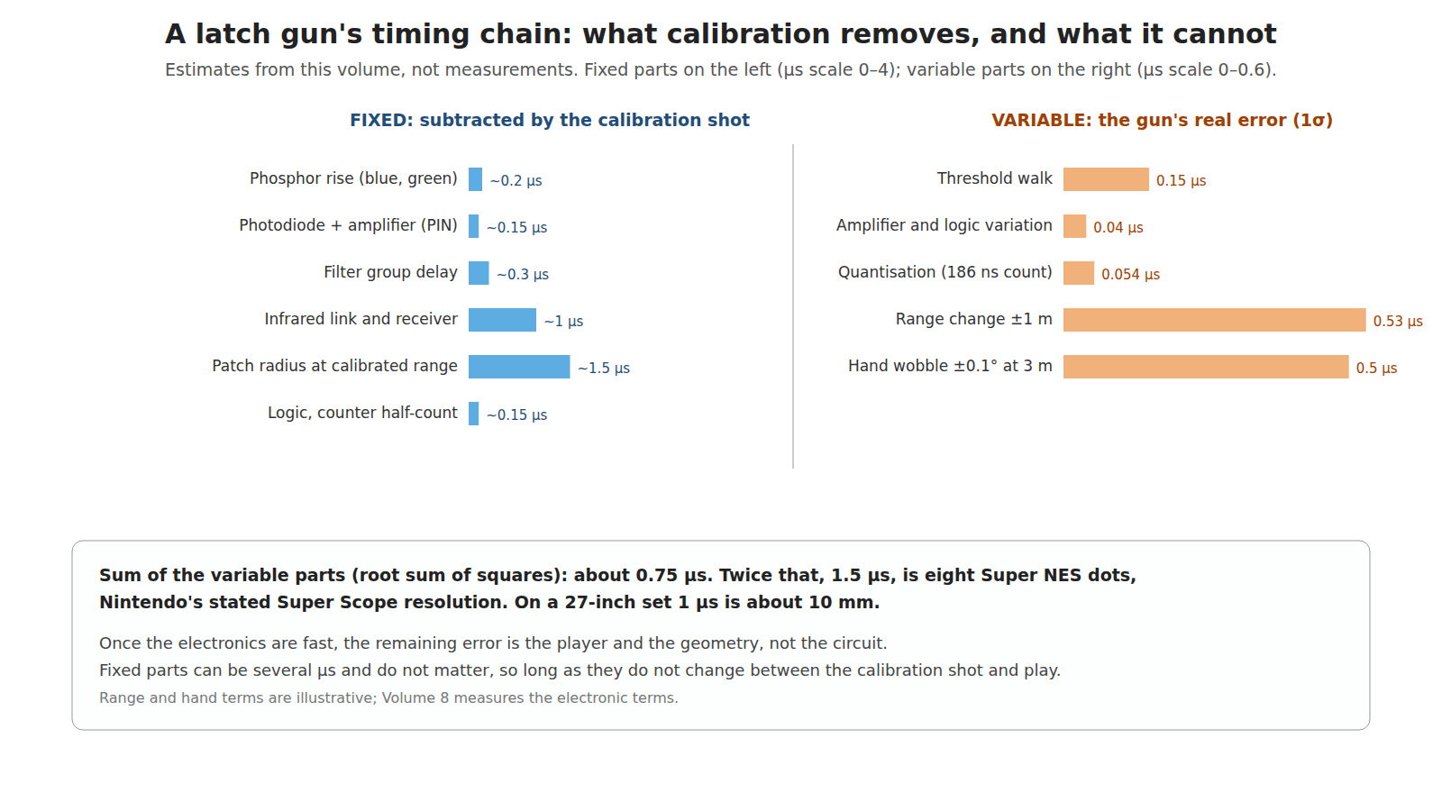
The governing rule from Volume 1 §1.8 is that a constant delay is subtracted by calibration and only its variation is error. So each link of the chain gets two numbers.
Table 3 — 5.4 Every delay, fixed or variable
| Link | Fixed part (calibrated away) | Variable part (error) | Basis |
|---|---|---|---|
| Phosphor rise | well under 1 µs for the blue and green phosphors | depends on the target’s colour; red contributes almost no edge | Volume 2 |
| Optical edge and threshold walk | the threshold crossing on a nominal target | tens to a few hundred ns with brightness, colour, focus, partial fill | Volume 3 §3.7 |
| Photodiode and amplifier | ~0.1 µs (PIN and a fast TIA) to a few µs (phototransistor) | small for a PIN stage; a significant fraction of the rise for a phototransistor | Volume 3 §3.4–3.5 |
| Filter group delay | set by the filter | small for a fixed design | — |
| Infrared link (Super Scope, Menacer) | LED, receiver and its gating logic | small if the receiver is fast | SNES Development Manual,6 Ryves7 |
| Logic between sensor and latch | gate propagation | supply- and temperature-dependent; large for slow CMOS | Ryves found CD4001B CMOS poor and SN74ALS00 TTL “greatly improved”7 |
| Counter quantisation | half a count on average | one count peak to peak | §5.3 |
| Timing reference | none inside the console | GunCon: its sync separator’s response to a sync edge allowed up to 0.25 µs to rise | psx-spx, ITU-R BT.470-689 |
| Patch geometry (§5.5) | patch radius at the calibrated range | changes with range and with how the patch straddles the target | this volume |
| The player’s hand | — | every 0.1° of wobble at 3 m is 5 mm, about 0.5 µs | geometry |
Ben Ryves’s adaptors show the fixed-delay rule at work. Feeding a Light Phaser’s output into a Mega Drive in place of a Menacer, he found the game placed the cursor a consistent distance left of the true aim point, which he attributed to the wireless Menacer’s extra infrared hop being missing; a 220 Ω and 100 nF RC delay, about 22 µs of time constant, improved the aim.7 The game had been calibrated, by Sega, for the Menacer’s fixed delay, and a gun with a shorter one needed the difference put back.
5.5 The left edge, and how far it is from the aim point
A latch gun fires on the first edge it sees, and the first edge on any line is where the beam enters the patch: its left boundary (Volume 1, §1.6). SMS Power puts it plainly for the Light Phaser: the coordinates “define some part, or all, of the left boundary of the sensor’s ‘seen’ circle”, and the game has to estimate the centre.3
The size of that offset is easy to work out. On a line at height y above or below the centre of a patch of radius r, the left edge is at a horizontal distance √(r² − y²) left of centre. Near the middle of the patch that is almost exactly r.
Table 4 — 5.5 The left edge, and how far it is from the aim point
| Where the latch fires | Horizontal offset from the aim point | At 3 m (32 mm patch, r = 16 mm) |
|---|---|---|
| First line of the patch (top) | ~0 (the chord is short) | ~0, but Y is a radius high |
| The Menacer’s eighth of ~20 lines | √(1 − (2/10)²) × r ≈ 0.98 r | ~16 mm, ~1.5 µs |
| Middle line | r | 16 mm, 1.5 µs |
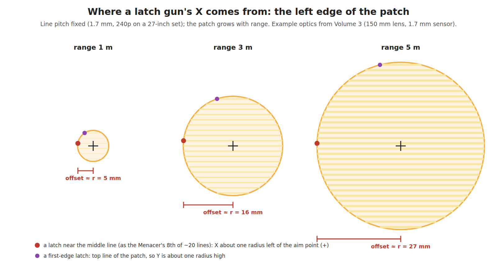
So the Menacer’s receiver, which counts eight light pulses before latching (as Ryves reads the patent), puts Y near the middle of the patch but leaves X about one patch radius left of the aim point.7 That is a fixed offset at a fixed range, and the calibration shot removes it. The trouble is that the patch radius is proportional to range (Volume 3, §3.2): with Volume 3’s example optics it is about 5 mm at 1 m, 16 mm at 3 m and 27 mm at 5 m. A gun calibrated at 3 m and then fired from 5 m lands its shots about 11 mm left of the aim point, purely from patch geometry (the reported left edge moves out from 16 mm to about 27 mm while the calibration still adds back 16), on top of the sight-line parallax the Super Scope manual describes.6 It is the same kind of error as parallax, and it has the same cure: calibrate from where you will play.
Three ways to reduce it, from the sources:
- Average several lines and extrapolate. SMS Power recommends “some sort of averaging and extrapolation to arrive at a center position of the scanned circle”, and the Master System’s free-running latch makes it possible: the program polls TH line after line and reads each frozen value.3 The left edges on successive lines trace the left half of the circle; its leftmost point is one radius from the centre at the circle’s middle line.
- Latch both edges. The centre of a line’s chord is the mean of its left and right edges, and it is independent of range. The Master System cannot do this: its hardware does not latch the falling edge.3 An in-gun timer, like the GunCon’s, could, but nothing in the sources read says the GunCon does.
- Choose the latch line deliberately. The Menacer’s eighth-line rule is a cheap, fixed approximation to (1) for Y.
5.6 Y: exact, but which line?
The vertical coordinate is a count of lines, so it has no quantisation error worth mentioning: one line is 1.7 mm on a 27-inch set in 240p. Its error is in which line gets counted. A latch that fires on the first edge in a frame reports the top of the patch, a radius above the aim point. The Super Scope’s mapping, Y = OPVCT − 1 before calibration,1 shows a console treating the latched line as nearly the aim line and leaving the rest to calibration.
Brightness moves it too. The first line of the patch crosses only a short chord, so its pulse is short and dim (Volume 1, §1.6); whether that line reaches the threshold depends on target brightness and the threshold setting. A bright target latches a line or two higher than a dim one. That is threshold walk in the vertical axis, quantised to lines.
5.7 A latch in software: the PlayStation’s IRQ10
The PlayStation shows what happens without a hardware latch. Its controller port’s pin 8 goes straight to the interrupt controller as IRQ10, and psx-spx records Martin Korth’s verdict: Sony “did apparently ‘forget’ to latch the current cathode ray beam coordinates by hardware when sensing the lightgun signal”.5 Konami’s Justifier and Hyper Blaster instead raise IRQ10, and the interrupt handler reads two timers configured to follow the video.
The variable delay of that path is the CPU’s interrupt latency: “if the main program is trying to read a mul/div/gte result while the mul/div/gte operation is still busy may stop the CPU for some dozens of clock cycles, and active DMA transfers or cache hits and misses in the IRQ handler may cause different timings”.5 Dozens of cycles of a 33.9 MHz CPU are of order a microsecond, five SNES-sized dots, and they vary from shot to shot. The workaround psx-spx describes is clever: treat the first IRQ10 only as notice that the beam is in the patch, then disable DMA, sit in a tight loop polling the interrupt status bit, and read the timers when the next line’s IRQ10 arrives, so that the latency is a short, repeatable polling loop instead of a full interrupt entry.5 That is a software latch built from a busy-wait, and it is exactly the trade Nintendo’s manual refused for the Super Scope: “This processing speed cannot be achieved by most micro-computers”.6
Namco’s answer, the GunCon, took the timing out of the console altogether and put a counter in the gun (History of Light Guns, Volume 5). Its price is that the gun’s timing reference is now a sync pulse separated from composite video by a BA7071F, not the console’s internal counter (Volume 3, §3.8). psx-spx notes that “theoretically, some GunCon guns might have problems to extract Vsync/Hsync from either PAL or NTSC composite signals”, which is the failure mode that design accepts.5
(The 33.9 MHz CPU clock is the PlayStation’s commonly quoted figure; it was not read in a primary source for this dive.)
5.8 The budget, summed
Nintendo’s own figure for the Super Scope is a resolution of “about 1 character (8 dots, in x and y orientation)”.6 Eight dots is 1.5 µs, or about 15 mm on a 27-inch set. A plausible budget for a well-made latch gun of the Super Scope’s type, with the variable terms from §5.4 combined as independent errors (root sum of squares):
Table 5 — Nintendo's own figure for the Super Scope is a resolution of "about 1 character (8 dots, in x and y orientation)".[^snesdm] Eight dots is 1.5 µs, or about 15 mm on a 27-inch set. A plausible budget for a well-made latch gun of the Super Scope's type, with the variable terms from §5.4 combined as independent errors (root sum of squares)
| Variable term | Estimate (1σ) |
|---|---|
| Quantisation, 186 ns count | 0.05 µs |
| Threshold walk over typical targets | 0.1–0.2 µs |
| Amplifier and logic variation | under 0.05 µs |
| Range change of ±1 m about the calibration range | ~0.5 µs (§5.5) |
| Hand wobble, ±0.1° at 3 m | ~0.5 µs |
| Root sum of squares | about 0.7–0.8 µs |
A 2σ spread of about 1.5 µs is eight dots, Nintendo’s figure. The agreement is partly by construction, because the hand and range terms are illustrative rather than measured, but it makes the useful point: once the electronics are fast, the remaining error is the player and the geometry, not the circuit. The electronics’ share of a CRT gun’s error was never more than about a dot. That is also why no CRT gun bothered with a faster counter than its console’s dot clock: there was nothing left to gain from one.
Volume 8 gives the bench procedure that replaces the estimates in this table with measurements.
5.9 What could not be verified
- Whether the Mega Drive’s HV latch re-arms after a read; MacDonald did not know.
- Whether the GunCon latches only the rising edge or also the falling one.
- The size of the hand-wobble term. No physiological measurement of aim tremor was read; ±0.1° is an illustration.
- The PlayStation CPU clock (33.9 MHz) and therefore the IRQ10 latency in microseconds.
- The Menacer’s eighth-pulse rule and the 10 µs infrared pulses are Ben Ryves’s reading of the Menacer patent; the patent itself was not read.
Sources
Footnotes
-
Martin Korth (nocash), fullsnes, “SNES PPU Timers and Status” (213Ch/213Dh OPHCT/OPVCT, 213Fh STAT78, “Lightgun Coordinates”), https://problemkaputt.de/fullsnes.htm, read 2026-10-19. ↩ ↩2
-
Charles MacDonald, “Sega Master System VDP documentation” (2002), section 11, “Display timing”, read 2026-10-19 via the Internet Archive copy of https://www.smspower.org/uploads/Development/msvdp-20021112.txt. ↩ ↩2
-
SMS Power!, “Light Phaser” (Development), https://www.smspower.org/Development/LightPhaser, read 2026-10-19. ↩ ↩2 ↩3 ↩4
-
Charles MacDonald, “Sega Genesis VDP documentation”, version 1.5f (2000), “Interrupts” and section 5, “HV Counter”, read 2026-10-19 via the Internet Archive. ↩ ↩2
-
Martin Korth (nocash), psx-spx, “Controllers — Lightguns”, including “Konami IRQ10 Notes” and “Namco (GunCon)”, https://psx-spx.consoledev.net/controllersandmemorycards/, read 2026-10-19. ↩ ↩2 ↩3 ↩4 ↩5 ↩6
-
Nintendo of America, Super NES Development Manual, Book II, Section 4, “Super NES Super Scope”, §1 (specification), §3.1 (principle), §3.4.4 (raster signal transmission timing) and §4 (receiver). Internet Archive item
SNESDevManual, read 2026-10-19. ↩ ↩2 ↩3 ↩4 ↩5 ↩6 -
Ben Ryves, journal entries of 18 and 26 March 2020, https://benryves.com/journal/date/2020/3, read 2026-10-19. ↩ ↩2 ↩3 ↩4
-
Martin Korth (nocash), psx-spx, “Pinouts — Component List and Chipset Pin-Outs for Namco Lightgun, NPC-103”, https://psx-spx.consoledev.net/pinouts/, read 2026-10-19. ↩
-
International Telecommunication Union, Recommendation ITU-R BT.470-6 (11/1998), Table 1-1, read 2026-10-19. ↩
Comments (0)