CRT Timing · Volume 3
The Front End — Lens, Photodiode, Amplifier, Filter and Threshold
How big a patch the lens sees and how much light it gets, photodiode against phototransistor, transimpedance bandwidth, the line-rate filter, threshold walk, and the classic guns' sensor chains redrawn
3.1 The chain
Every CRT light gun, from the 1970s to the GunCon 2, has the same chain between the screen and the console. Only the last block differs between the two methods.
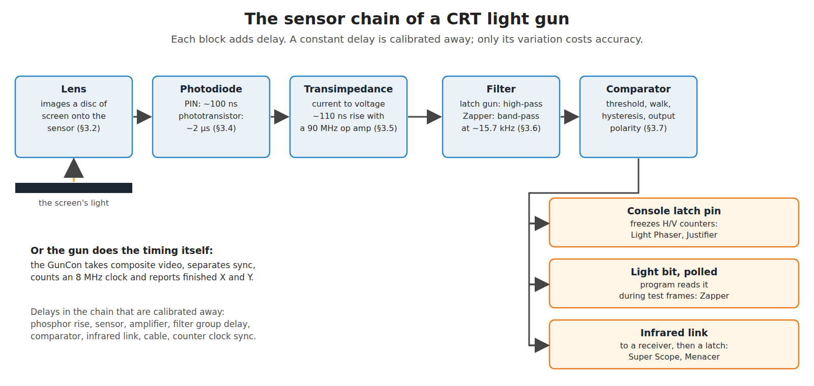
The job of the chain is narrow: deliver to the console an edge at a fixed delay after the beam enters the patch, and nothing at any other time. Every design decision below is about keeping that delay short, keeping it constant, and keeping everything else out.
3.2 The lens decides the patch
A light gun’s lens forms an image of the screen at the photodiode. The photodiode’s sensitive area, projected back through the lens, is the patch of screen the gun sees. For a thin lens of focal length f at distance d from the screen, the magnification is f ÷ (d − f), so a sensor s wide sees a patch about s × (d − f) ÷ f wide.
Nintendo’s development manual gives the one complete optical specification in the sources read: the Super Scope’s lens is “f = 150 mm, 30 mm diameter”, and its range is 3.28 to 16.4 ft, about 1 to 5 m.1 The manual does not give the sensor size, so take a 1.7 mm sensor as an example:
Table 1 — Nintendo's development manual gives the one complete optical specification in the sources read: the Super Scope's lens is "f = 150 mm, 30 mm diameter", and its range is 3.28 to 16.4 ft, about 1 to 5 m.[^snesdm] The manual does not give the sensor size, so take a 1.7 mm sensor as an example
| Range | Magnification | Patch for a 1.7 mm sensor | 240p lines crossed (27-inch set, 1.7 mm pitch) |
|---|---|---|---|
| 1 m | 0.18 | 9.6 mm | about 6 |
| 3 m (the manual’s best-alignment range) | 0.053 | 32 mm | about 19 |
| 5 m | 0.031 | 55 mm | about 32 |
Three consequences follow, and they apply to any CRT gun:
- The patch grows with range. At 5 m the gun sees five times as many lines as at 1 m, and the left edge of the patch moves further from the aim point. A latch gun that reports the left edge (Volume 1, §1.6) therefore has a range-dependent horizontal offset unless the game finds the centre (Volume 5).
- A long focal length keeps the patch small at range. That is why the Super Scope is mostly an empty tube: History of Light Guns, Volume 4 notes that the barrel length is the focal length. A pistol-sized gun with a short lens sees a larger patch at the same range.
- The sight line and the lens axis cross at one range only. Nintendo’s manual says alignment is best at 3 m and offsets grow either side.1 This parallax is a calibration problem, not a sensor one, and it is taken up in Aiming Maths and Calibration.
The GunCon’s component list in psx-spx records a 20 mm lens and a three-pin light sensor “with metal shielding”.2 Its focal length was not found.
3.3 How much light arrives
The useful fact from radiometry is that the irradiance in the image of an extended source does not depend on the range: it is set by the source’s luminance and the lens’s f-number, roughly πL ÷ (4N²) for luminance L and f-number N. Moving back from the screen makes the patch bigger but the light per square millimetre on the sensor stays the same, so long as the target is larger than the patch. When the target is smaller than the patch, as a small white sprite is at long range, the signal falls with the square of the range, because the sensor’s area fills with dark screen around the target.
An order-of-magnitude estimate for the Super Scope, with every assumption stated:
Table 2 — An order-of-magnitude estimate for the Super Scope, with every assumption stated
| Step | Assumption or working | Result |
|---|---|---|
| f-number | 150 mm ÷ 30 mm | N = 5 |
| Screen luminance, white, averaged over the frame | assumed 100 cd/m² | — |
| Average illuminance on the sensor | π × 100 ÷ (4 × 25) | about 3 lux |
| Fraction of the frame during which the patch is being lit | 20 pulses × 3.3 µs ÷ 16.7 ms (Volume 1, §1.6) | about 0.4 % |
| Illuminance during a pulse (fast phosphors only) | 3 lux ÷ 0.004, ignoring the slow tails | of order 1,000 lux |
| Photocurrent, BPW34 with a 2.3 mm² image | Vishay: 75 µA at 1,000 lux over 7.5 mm²3 | of order 20 µA |
That figure is an upper bound for several reasons. Vishay’s figure is for CIE illuminant A, a tungsten source rich in near-infrared, where silicon is most sensitive; CRT phosphor light is all visible, so the true current for the same lux is several times lower. Part of the light is in the slow tails, not the pulse; and the lens and the screen glass lose some. A peak photocurrent of a few microamperes from a white target, and well under a microampere from a dim one, is the realistic design range. That is small enough that the amplifier has to be a real transimpedance stage, and large enough that photodiode noise is not the limit (§3.5).
3.4 Photodiode or phototransistor
Table 3 — 3.4 Photodiode or phototransistor
| PIN photodiode (Vishay BPW34) | Phototransistor (Vishay BPW85, TEPT4400 class) | |
|---|---|---|
| Speed | rise and fall 100 ns at VR = 10 V, RL = 1 kΩ3 | BPW85: about 2 µs rise, 2.3 µs fall (distributor listing; test load not shown)4 |
| Capacitance | 70 pF at 0 V, 25 pF at 3 V reverse bias3 | collector–base capacitance multiplied by the transistor’s gain (the Miller effect), which is why it is slow; TEPT4400 CCE 16 pF5 |
| Output | a current proportional to light, linear over decades | a current about a hundred times larger, gain varying from part to part (TEPT4400 sold in three binned gain groups, 15–70 µA at 20 lux)5 |
| Needs | an amplifier | only a load resistor |
The Super Scope used “a pin photo-diode”, in Nintendo’s words.1 The Light Phaser’s output stage is a single transistor in open-collector form with a 1 kΩ pull-up, according to Ben Ryves, who built adaptors around it; what sits in front of that transistor was not documented in the sources read.6
The speed row decides it for a latch gun. A 2 µs rise is three-fifths of the whole 3.3 µs pulse of Volume 1, and where along a 2 µs ramp the threshold is crossed depends on how bright the target is (§3.7). At 186 ns per Super NES dot, a microsecond of ramp is five dots of brightness-dependent error. A PIN photodiode with a fast amplifier puts the ramp at around 100 ns, half a dot. For a flash-frame gun, which only has to notice that light arrived at some point in a 16.7 ms frame, a phototransistor’s speed is irrelevant.
3.5 Transimpedance and bandwidth
A photodiode into a resistor is a current source into an RC. With the BPW34’s 25 pF at 3 V reverse bias:
Table 4 — A photodiode into a resistor is a current source into an RC. With the BPW34's 25 pF at 3 V reverse bias
| Load | Time constant | 10–90 % rise | Signal from 2 µA |
|---|---|---|---|
| 1 kΩ | 25 ns | 55 ns | 2 mV: too small |
| 10 kΩ | 250 ns | 0.55 µs | 20 mV |
| 100 kΩ | 2.5 µs | 5.5 µs: slower than the pulse | 200 mV |
Speed and signal fight each other in a resistor load. The transimpedance amplifier separates them: the photodiode drives the virtual earth at an op amp’s inverting input, so its capacitance sees almost no voltage swing, and the feedback resistor RF sets the gain. Its bandwidth is approximately √(GBW ÷ (2π RF Cin)), where Cin is the photodiode plus amplifier input capacitance, with a small feedback capacitor added for stability.
Worked for TI’s OPA380, a transimpedance op amp with a 90 MHz gain-bandwidth product,7 a BPW34 at 3 V and RF = 47 kΩ:
- Cin ≈ 25 pF + a few pF ≈ 30 pF
- bandwidth ≈ √(90 MHz ÷ (2π × 47 kΩ × 30 pF)) ≈ 3.2 MHz
- 10–90 % rise ≈ 0.35 ÷ 3.2 MHz ≈ 110 ns
- output for 2 µA: 94 mV, for 20 µA: 0.94 V
That is the right region: a rise time under one Super NES dot, and a signal a comparator can use. The arithmetic is the standard first-order approximation and the circuit has not been built; the real bandwidth also depends on layout capacitance and the stability capacitor.
The contrast with an integrated “light-to-voltage” sensor is instructive. TI’s OPT101 is a photodiode and transimpedance amplifier in one package, with 0.45 A/W at 650 nm, and its datasheet gives a bandwidth of 14 kHz and a rise time of 28 µs with its internal 1 MΩ feedback resistor.8 A rise of 28 µs is nearly half a scan line. It is a fine ambient-light sensor and useless for a timing gun, and it is the kind of part a builder reaches for first because it is so convenient.
Noise is not the limit. Timing jitter from noise on an edge is σt ≈ σv ÷ (dV/dt). With a 110 ns edge and a signal-to-noise ratio of 20 at the threshold, σt is roughly 110 ns × 0.8 ÷ 20 ≈ 4 ns, a fiftieth of a dot. The errors that matter come from the light, not the amplifier: the brightness-dependent threshold crossing (§3.7) and the geometry of the patch (Volume 5).
3.6 Filtering: high-pass for a latch gun, band-pass for a Zapper
The photocurrent carries four things: the fast pulses, the slowly building afterglow pedestal (Volume 2, §2.7), room light and its flicker, and noise. The two methods filter it differently because they need different things from it.
A latch gun needs the edges. It uses a high-pass filter, AC coupling, with its corner well below the pulse’s own frequency content and well above the flicker of lamps. A 3 µs pulse has most of its energy above 100 kHz; mains-powered lamps flicker at 100 or 120 Hz and their harmonics; the afterglow pedestal changes over milliseconds. A corner of a few kilohertz to a few tens of kilohertz passes the edges almost untouched and removes the rest. The high-pass also differentiates slightly, sharpening what it passes.
A flash-frame gun needs only to know that a burst happened. The Zapper therefore uses a band-pass filter at the line rate. The NESdev wiki describes its Sharp IR3T07A as a filter “tuned approximately to the CRT scanline frequency (~15 kHz)”,9 and an independent bench test summarised in History of Light Guns, Volume 3 found it responding between roughly 13.5 and 20 kHz. A band-pass filter turns a burst of line-rate pulses into a burst of line-rate sine waves, and a detector after it puts out the envelope. The envelope rises over several lines and decays over several lines, which is why the Zapper’s light bit stays active for 19 to 26 lines rather than for the 3 µs of each pulse.9 All information about where in the line the light arrived is lost in that process, and the flash-frame method never needed it.
The band-pass also does something a high-pass cannot. It rejects light that is fast but not periodic at the line rate, a camera flash, for instance, and it rejects line-rate light only if it arrives as a sustained burst. A lamp cannot produce a 15.7 kHz burst, and neither can any flat panel (Volume 6). The NESdev wiki notes that some clone Zappers, the Tomee Zapp Gun and Simba’s Jr among them, “have a much weaker filter that responds more readily to these slower changing light sources”, which is the property that later made them the basis for lag-compensated play on LCDs (Volume 7).9
The IR3T07A itself is undocumented. MAME’s source records that the NES, Vs. System and PlayChoice-10 guns and R.O.B. “all use a Sharp IR3T07, though the NES zapper is (always?) seen with the IR3T07A revision”.10 No Sharp datasheet was found.
3.7 Threshold, threshold walk and the output stage
The comparator after the filter decides when an edge has arrived. Three design issues meet here.
Threshold walk. A comparator fires when the signal crosses a fixed voltage. A real edge has a finite rise, so a bright target crosses the threshold early in the rise and a dim one crosses late. The difference is a horizontal shift that depends on the target’s brightness and colour.
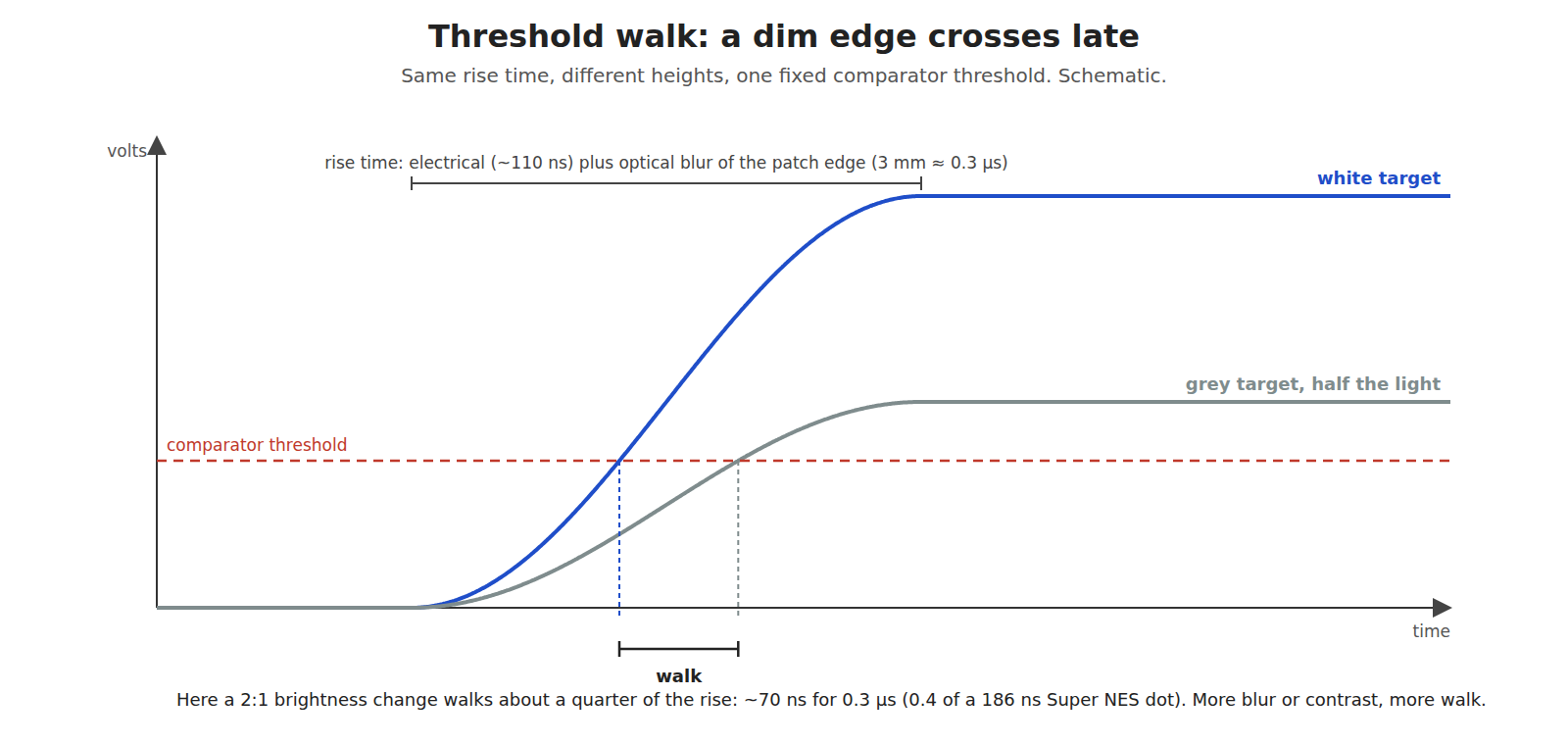
The electrical rise is not the whole edge. The light pulse begins as the beam enters the patch image, and that image has a blurred boundary whenever the gun is not at its focus distance. A boundary blurred over 3 mm of screen, at 10.4 mm/µs, is an optical rise of about 0.3 µs before any electronics. For a two-to-one change in target brightness, threshold walk across that edge is roughly a quarter of it, about 70 ns or under half a dot; a gun further out of focus, or a target that fills only part of the patch, walks proportionally more. It explains two reports in psx-spx about the GunCon: coordinates near the left edge of the screen are the most fragile, and white text on black gives “jumpy” results, “returning the position of the closest white pixels”.11 Where the target fills only part of the patch, the pulse’s height and shape change from line to line and shot to shot, and so does the crossing.
Adaptive or fixed threshold. A fixed threshold is simple and walks with brightness. An adaptive one, set from the recent peak, walks less. Modern Mallard’s 2018 replacement Zapper board (photodiode, transimpedance amplifier, a gain stage with servo and a PIC16F18313 that samples the result) needs about 64 ms of screen view before a shot to set its slicer level, according to its designer’s announcement: an adaptive threshold in practice.12
The output stage and the console’s logic. The console end decides polarity and speed. The Super NES latches on “a high-to-low transition (pin 6 of 2nd controller connector)”;13 the Master System latches its horizontal counter when the TH line goes low;14 the Light Phaser drives TH with an open-collector transistor.6 Speed also matters in the logic that follows. Ryves found that a latch built from a CD4001B CMOS gate, as drawn in the Menacer patent, performed “just about as badly” as a counter circuit, while an SN74ALS00 TTL gate “greatly improved” it.6 Slow CMOS at 5 V has propagation delays that vary with supply voltage, temperature and load, and every nanosecond of that variation lands on the X axis.
3.8 The classic chains redrawn
The sources read give the sensor chains of five classic guns at block level. None of them gives a full component-level schematic that could be checked, so none is redrawn here at component level. Furrtek’s Light Phaser schematic is linked from SMS Power,14 and a reverse-engineered GunCon schematic was published at nicolaselectronics.be, a page that no longer exists and was not archived.2
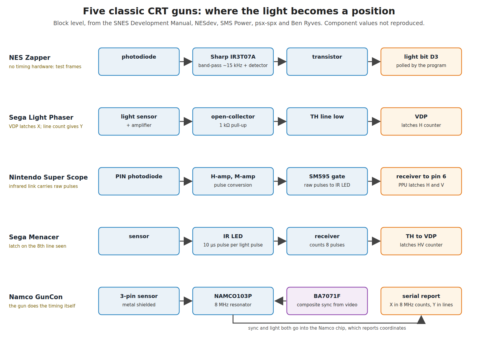
Table 5 — 3.8 The classic chains redrawn
| Gun | Sensor | Filter and decision | Where the timing is done | Source |
|---|---|---|---|---|
| NES Zapper | photodiode | Sharp IR3T07A: line-rate band-pass and envelope detector | nowhere: the program polls a light bit through test frames | NESdev, MAME910 |
| Sega Light Phaser | light sensor (type not documented here) | amplifier, open-collector output to TH | the Master System VDP latches its H counter on TH going low | SMS Power, Ryves146 |
| Nintendo Super Scope | PIN photodiode | ”H-amp” and “M-amp for signal amplification and pulse conversion” | the Super NES PPU, via an infrared link and receiver to the pin 6 latch | SNES Development Manual1 |
| Sega Menacer | sensor (type not documented here) | in the gun; light pulses sent as 10 µs infrared pulses | the Mega Drive VDP, after the receiver counts eight light pulses | Ryves, from the Menacer patent6 |
| Namco GunCon | ”3pin Light sensor with metal shielding” | in the sensor and the NAMCO103P | in the gun: a Rohm BA7071F sync separator on the composite video and an 8 MHz ceramic resonator (“CSA 8.00WT”) clock the NAMCO103P’s counters | psx-spx2 |
The GunCon’s row is the one to study. Its BA7071F has a horizontal-sync output and a vertical-sync output, but psx-spx records both as unconnected; only the composite sync output goes to the Namco chip, which separates lines and fields itself.2 Its timing reference is therefore the composite sync edge, which ITU-R BT.470-6 allows to take up to 0.25 µs to rise (Volume 1, §1.3), and its timebase is a ceramic resonator, not a crystal. Neither matters much against the 125 ns count, which is why the gun works; both are part of its error budget in Volume 5.
3.9 A bench sensor: why this, and why not the others
Volume 8 measures a CRT, a sensor and a classic gun on the Analog Discovery Pro ADP3450 (owner decision D9, recorded in the Light Guns decision log). It needs a reference sensor whose own delay is short and known, and a clean sync reference. Nothing here is for the build’s own gun, which uses a camera (IR Point Tracking); this is test equipment.
Sensor: BPW34 into an OPA380 transimpedance stage (proposed).
Table 6 — Sensor: BPW34 into an OPA380 transimpedance stage (proposed).
| Option | For | Against | Verdict |
|---|---|---|---|
| Vishay BPW34 + TI OPA380, RF about 47 kΩ | 100 ns diode; ~110 ns stage rise by the §3.5 estimate; both parts documented by their makers; OPA380 is ACTIVE at TI | needs a small board and a 3 V bias | Chosen |
| TI OPT101 | one part, no layout | 14 kHz, 28 µs rise:8 slower than half a scan line | Rejected |
| Phototransistor (BPW85, TEPT4400) | large output, no amplifier | ~2 µs rise (distributor figure); gain binned 15–70 µA:5 walk of several dots | Rejected |
| The classic gun’s own sensor | measures the real gun | its delay is what is being measured; no independent reference | Used as the device under test, not as the reference |
Sync reference: the console’s composite video straight into an ADP3450 channel, with a sync separator only for the digital channels (proposed).
Table 7 — Sync reference: the console's composite video straight into an ADP3450 channel, with a sync separator only for the digital channels (proposed).
| Option | For | Against | Verdict |
|---|---|---|---|
| Composite video into an analogue channel, trigger on the sync tip | no part; the edge is the real reference the GunCon also uses; the ADP3450’s ≥55 MHz input sees the 0.25 µs sync edge properly | triggering on sync among picture content needs a level and holdoff set by hand | Chosen for the analogue measurements |
| TI LMH1980 sync separator | ACTIVE at TI; composite, horizontal, vertical and odd/even outputs at 3.3 to 5 V; NTSC, PAL, 480i and more15 | adds its own delay; its behaviour on non-standard 240p (262 lines, no half line) is not stated by TI | Chosen for the logic-analyser channels, checked against the analogue sync |
| TI LM1881 | the classic part, used in countless retro projects; vertical and odd/even outputs16 | TI lists it as LAST TIME BUY17 | Rejected for a new build; usable if one is in the drawer |
| Rohm BA7071F (the GunCon’s part) | known to work in a light gun | not read for this dive; status unknown | Not considered further |
Prices for the BPW34, OPA380 and LMH1980 were not captured: Digi-Key and Mouser refuse automated reading, and TI’s product pages show no price without a session. Purchase links: BPW34 datasheet at Vishay, OPA380 at TI, LMH1980 at TI, each with distributor links from the maker’s page.
3.10 What could not be verified
- The Super Scope’s and GunCon’s sensor sizes and the GunCon’s focal length; the patch sizes in §3.2 use an assumed 1.7 mm sensor.
- The photocurrent in §3.3 is an order-of-magnitude estimate from assumed screen luminance and a datasheet figure for a different light source.
- The BPW85’s 2 µs rise time is from a distributor’s listing, not Vishay’s datasheet.
- The Sharp IR3T07A’s internal design, and the Light Phaser’s and Menacer’s sensor types.
- Whether the LMH1980 locks to 240p.
- The OPA380 stage’s bandwidth is a first-order calculation, not a measurement.
Sources
Footnotes
-
Nintendo of America, Super NES Development Manual, Book II, Section 4, “Super NES Super Scope”, §1 (specification) and §3.2 (light receiver/amplifier). Internet Archive item
SNESDevManual, read 2026-10-19. ↩ ↩2 ↩3 ↩4 -
Martin Korth (nocash), psx-spx, “Pinouts — Component List and Chipset Pin-Outs for Namco Lightgun, NPC-103”, https://psx-spx.consoledev.net/pinouts/, read 2026-10-19. ↩ ↩2 ↩3 ↩4
-
Vishay Semiconductors, BPW34 datasheet, document 81521, rev. 2.1, 23 August 2011, https://www.vishay.com/docs/81521/bpw34.pdf, read 2026-10-19. ↩ ↩2 ↩3
-
RS Components, Vishay BPW85 listing (typical rise time 2 µs, fall time 2.3 µs), https://uk.rs-online.com/web/p/phototransistors/8151263, via search 2026-10-19. Vishay’s own datasheet was not read. ↩
-
Vishay Semiconductors, TEPT4400 ambient light sensor datasheet, document 81341, rev. 1.8, 30 June 2016, https://www.vishay.com/docs/81341/tept4400.pdf, read 2026-10-19. ↩ ↩2 ↩3
-
Ben Ryves, journal entries of 18 and 26 March 2020, “Using a Master System Light Phaser in Mega Drive Menacer games” and “Fixing the Menacer detection but breaking the accuracy of the aim tracking”, https://benryves.com/journal/date/2020/3, read 2026-10-19. ↩ ↩2 ↩3 ↩4 ↩5
-
Texas Instruments, OPA380 datasheet, SBOS291G (November 2003, revised September 2007), https://www.ti.com/lit/ds/symlink/opa380.pdf, read 2026-10-19; product status ACTIVE on https://www.ti.com/product/OPA380, read 2026-10-19. ↩
-
Texas Instruments, OPT101 datasheet, SBBS002B (January 1994, revised June 2015), https://www.ti.com/lit/ds/symlink/opt101.pdf, read 2026-10-19. ↩ ↩2
-
NESdev Wiki, “Zapper”, https://www.nesdev.org/wiki/Zapper, read 2026-10-19 via the Internet Archive. ↩ ↩2 ↩3 ↩4
-
MAME source,
src/devices/bus/nes_ctrl/zapper_sensor.cpp(copyright holder “kmg”, BSD-3-Clause), https://github.com/mamedev/mame/blob/master/src/devices/bus/nes_ctrl/zapper_sensor.cpp, read 2026-10-19. ↩ ↩2 -
Martin Korth (nocash), psx-spx, “Controllers — Lightguns — Namco (GunCon)”, https://psx-spx.consoledev.net/controllersandmemorycards/, read 2026-10-19. ↩
-
Teuobk, “Modern Mallard: a kit to make the NES game Duck Hunt work on an LCD TV”, EEVblog forum, 28 June 2018, https://www.eevblog.com/forum/crowd-funded-projects/modern-mallard-a-kit-to-make-the-nes-game-duck-hunt-work-on-an-lcd-tv/, read 2026-10-19. ↩
-
Martin Korth (nocash), fullsnes, “SNES PPU Timers and Status”, https://problemkaputt.de/fullsnes.htm, read 2026-10-19. ↩
-
SMS Power!, “Light Phaser” (Development), https://www.smspower.org/Development/LightPhaser, read 2026-10-19. ↩ ↩2 ↩3
-
Texas Instruments, LMH1980 product page, “Auto-detecting SD/HD/PC video sync separator”, status ACTIVE, https://www.ti.com/product/LMH1980, read 2026-10-19. ↩
-
Texas Instruments, LM1881 datasheet, SNLS384G (February 1995, revised June 2015), https://www.ti.com/lit/ds/symlink/lm1881.pdf, read 2026-10-19. ↩
-
Texas Instruments, LM1881 product page, status “LAST TIME BUY”, https://www.ti.com/product/LM1881, read 2026-10-19. ↩
Comments (0)