CRT Timing · Volume 1
The Raster as a Clock — What a CRT Light Gun Measures, With the Numbers
Line and frame timing for broadcast NTSC and PAL and for the consoles' 240p, the pixel clocks, how fast the spot moves across a real tube, and what the patch of screen a gun looks at turns into in time
1.1 What this dive covers
This dive covers the engineering of the first generation of light guns: guns that worked out where they were pointing from the timing of a cathode-ray tube’s scan. It covers the phosphor the gun looks at, the photodiode and amplifier that turn that light into an edge, the two methods of using the edge, the counters and latches in the consoles, the numbers that set the accuracy limit, and why each later display (interlaced sets, 100 Hz sets, LCD, OLED) breaks the method. It ends with a bench procedure for measuring all of it on a real tube.
The story of these guns is told elsewhere on this site, and this dive does not repeat it. History of Light Guns tells it from 1934 to the present; its Volume 6 explains at signal level why flat panels ended the CRT gun. The per-gun identification tables are in Console Light Guns, Home-Computer Light Guns (which carries the latch registers of every home computer, from ANTIC to the Amiga’s Agnus) and Arcade Light Guns. Converting a classic gun for a modern television is a practical job, covered in Modding Classic Light Guns. This dive is the theory those dives rest on, with the arithmetic done.
1.2 A light source that tells the time
A colour CRT has three electron guns at the back of the neck, one each for red, green and blue. Magnetic deflection coils sweep the three beams together across the screen, left to right along a line and top to bottom down the frame, and a perforated mask or a grille of wires just behind the glass lets each beam strike only the phosphor stripes or dots of its own colour.
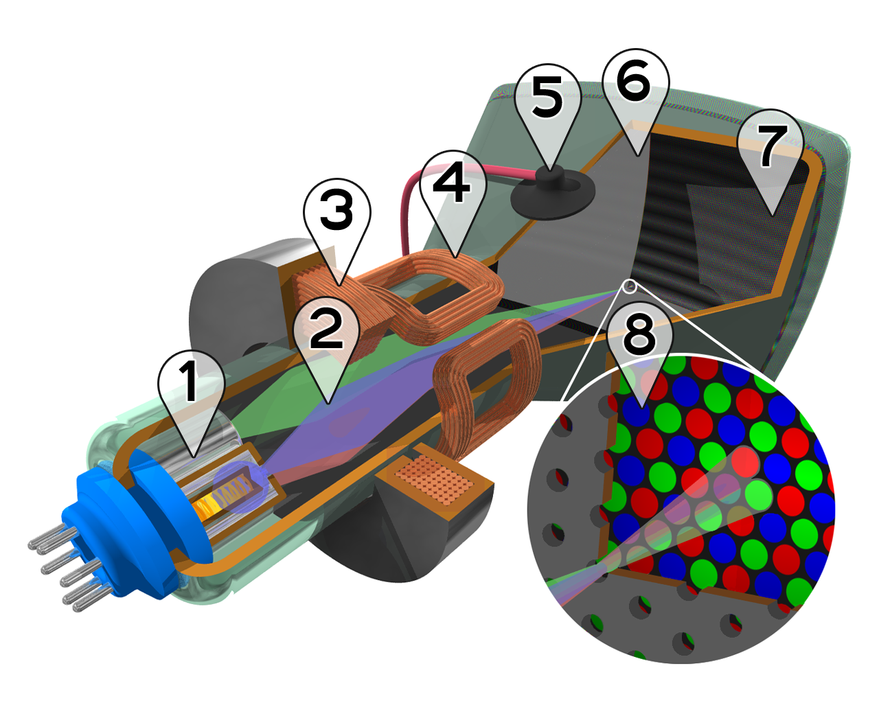
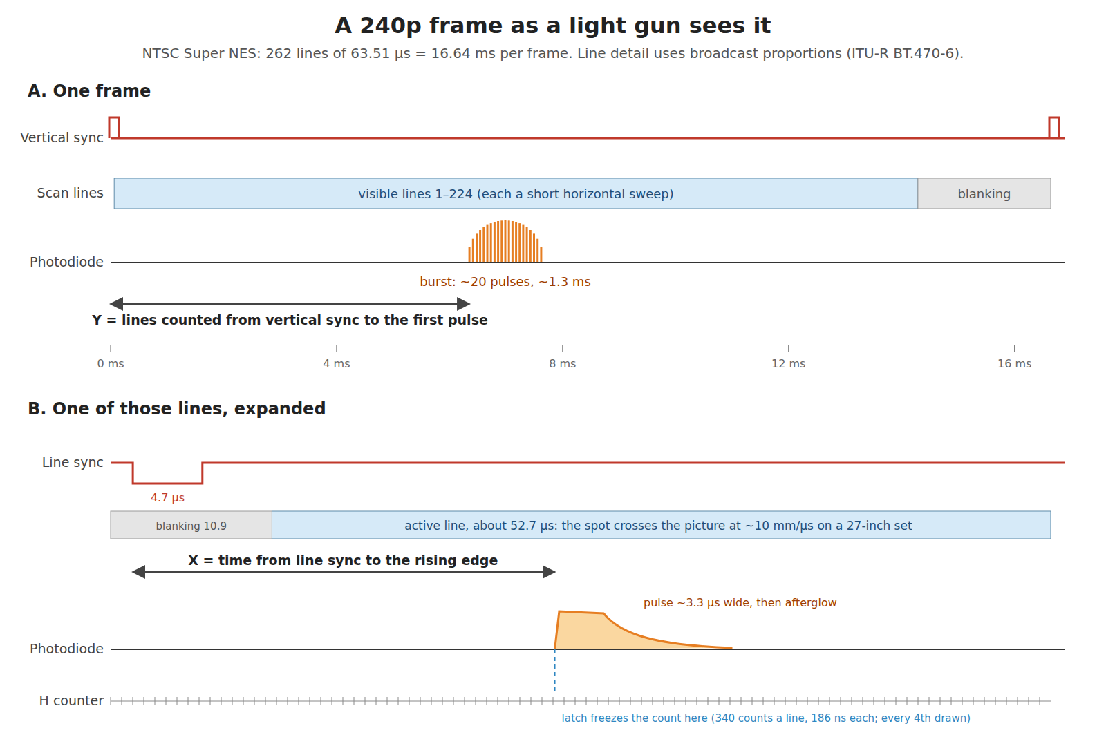
The property a light gun exploits is that the deflection is driven, directly and with no storage, by the synchronising pulses in the video signal. The horizontal oscillator is locked to the line-sync pulses and the vertical to the field-sync pulses. So a point on the glass is lit at one moment in each frame and only then: a fixed time after vertical sync, which fixes the line, and a fixed time after the start of that line, which fixes the position along it. Between those moments the phosphor fades (Volume 2).
A light gun is therefore a clock-reading instrument. It does not need to see the screen as an image. A single photodiode looking at a small patch of glass sees the patch light up at the moment the beam crosses it, and the console, which generated the sync pulses, already knows what time it is. Everything in this dive follows from that.
1.3 Broadcast timing: NTSC and PAL
The timing the television is built for is set by the broadcast standards. The figures below are from ITU-R Recommendation BT.470-6, which tabulates every analogue system; the values in the NTSC column are the ones it gives for M/NTSC.1
Table 1 — 1.3 Broadcast timing: NTSC and PAL
| Quantity | M/NTSC (525/60) | PAL B/G/I (625/50) |
|---|---|---|
| Lines per frame | 525 | 625 |
| Field rate | 60 Hz nominal (59.94 for colour) | 50 Hz |
| Line frequency | 15,734.264 Hz | 15,625 Hz |
| Line period | 63.5555 µs | 64 µs |
| Line blanking | 10.9 ± 0.2 µs | 12 µs (+0, −0.3) |
| Active line (period minus blanking) | about 52.7 µs | about 52 µs |
| Line-sync pulse | 4.7 ± 0.1 µs | 4.7 ± 0.2 µs |
| Sync-edge rise, 10–90 % | ≤ 0.25 µs | 0.2 ± 0.1 µs |
Two of those rows matter more than they look. The active line is the time the beam spends crossing the visible picture: about 52 µs in either system, so a light gun’s horizontal scale is the same, to within a few per cent, in NTSC and PAL. And the sync-edge rise time, a quarter of a microsecond, is the floor on how precisely anything outside the console can find the start of a line from the composite signal. That is the GunCon’s problem, because it times from sync it extracts itself (Volume 5).
Broadcast video is interlaced. Each frame is sent as two fields of 262.5 lines (NTSC) or 312.5 lines (PAL), and the half line shifts the second field down by half a line pitch so its lines fall between the first field’s. Volume 6 takes up what interlace does to a gun.
1.4 What the consoles actually send: 240p
Almost no light-gun game used broadcast timing. The NESdev wiki’s description of the NES video signal states the difference exactly: standard NTSC has 227.5 colour-subcarrier cycles per line and 262.5 lines per field, while the NES “generates 341 pixels, making 227 1/3 subcarrier cycles per scanline, and always generates 262 scanlines. This causes the TV to draw the fields on top of each other, resulting in a non-standard low-definition ‘progressive’ or ‘double struck’ video mode sometimes called 240p.”2 With no half line, every field lands on the same lines: 60 progressive frames a second, each a little over 240 visible lines.
Every console of the CRT-gun era used some form of this. The timings that matter to a gun:
Table 2 — Every console of the CRT-gun era used some form of this. The timings that matter to a gun
| Console | Source | Line period | Dot (pixel) clock | Dot time | Dots per line | Visible dots |
|---|---|---|---|---|---|---|
| NES (NTSC) | NESdev2 | 341 dots × 4 master clocks ÷ 21.477 MHz = 63.51 µs | 5.369 MHz | 186 ns (“around 186ns”) | 341 | 256 |
| Super NES (NTSC) | fullsnes3 | 1,364 master clocks ÷ 21.477 MHz = 63.51 µs | 5.369 MHz (master ÷ 4) | 186 ns | 340 (H counter 0–339) | 256 (counts 22–277) |
| Super NES (PAL) | fullsnes3 | — | 5.320 MHz | 188 ns | 340 | 256 |
| Master System, Mega Drive 32-cell | MacDonald45 | — | not stated in the sources read | — | 342 | 256 |
| PlayStation with GunCon | psx-spx6 | console’s own | the gun counts its own 8 MHz | 125 ns per count | — | 384 counts (04Dh–1CDh) |
Nintendo’s own Super Scope chapter rounds the dot time to “an amazing 180 nsec”.7 The exact figure is 4 ÷ 21.47727 MHz = 186.2 ns.
The consoles’ line is therefore 63.51 µs, not the broadcast 63.56 µs, and the line rate is 15.746 kHz, not 15.734 kHz. Fullsnes gives the SNES frame rate as 21.47727 MHz ÷ (262 × 1,364 − 2) = 60.0988 Hz.3 A television’s oscillators lock to either without complaint, which is why 240p worked on every set. Some digital processors do complain, and Volume 6 shows why that matters.
1.5 From time to millimetres on a real tube
A microsecond means nothing until it is put on the glass. Take a 27-inch 4:3 set, typical of the late CRT years, and assume for the arithmetic that the active picture fills the visible face (real sets overscan by a few per cent, which changes nothing below by more than that).
Table 3 — 1.5 From time to millimetres on a real tube
| Quantity | Working | Result |
|---|---|---|
| Picture width | 0.8 × 27 in (686 mm) diagonal | about 549 mm |
| Picture height | 0.6 × 686 mm | about 411 mm |
| Spot speed across the face | 549 mm ÷ 52.7 µs | about 10.4 mm per µs (10 km/s) |
| Width of one SNES dot | 186 ns × 10.4 mm/µs | about 1.9 mm |
| Line pitch in 240p | 411 mm ÷ 240 lines | about 1.7 mm |
| One microsecond of timing error | 10.4 mm/µs × 1 µs | about 10 mm, or 5.4 SNES dots |
| One line of vertical error | 1.7 mm |
Two conclusions fall straight out of the table.
The two axes are not alike. Vertically, a gun’s position is a count of lines, an integer, and an error of one line is under 2 mm. Horizontally, it is a time measurement, and every hundred nanoseconds of uncertainty is a millimetre on the glass. The horizontal axis is always the hard one, and it is hard in proportion to screen size: the same 1 µs is 10 mm on a 27-inch set and about 5 mm on a 14-inch portable.
The spot is fast. At 10 km/s the beam crosses a 1 mm phosphor stripe in about a tenth of a microsecond. The excitation of any one piece of phosphor is a pulse of order 100 ns, and what the gun sees afterwards is set by how that phosphor responds to such a pulse, which is the subject of Volume 2.
1.6 What the gun’s patch looks like in time
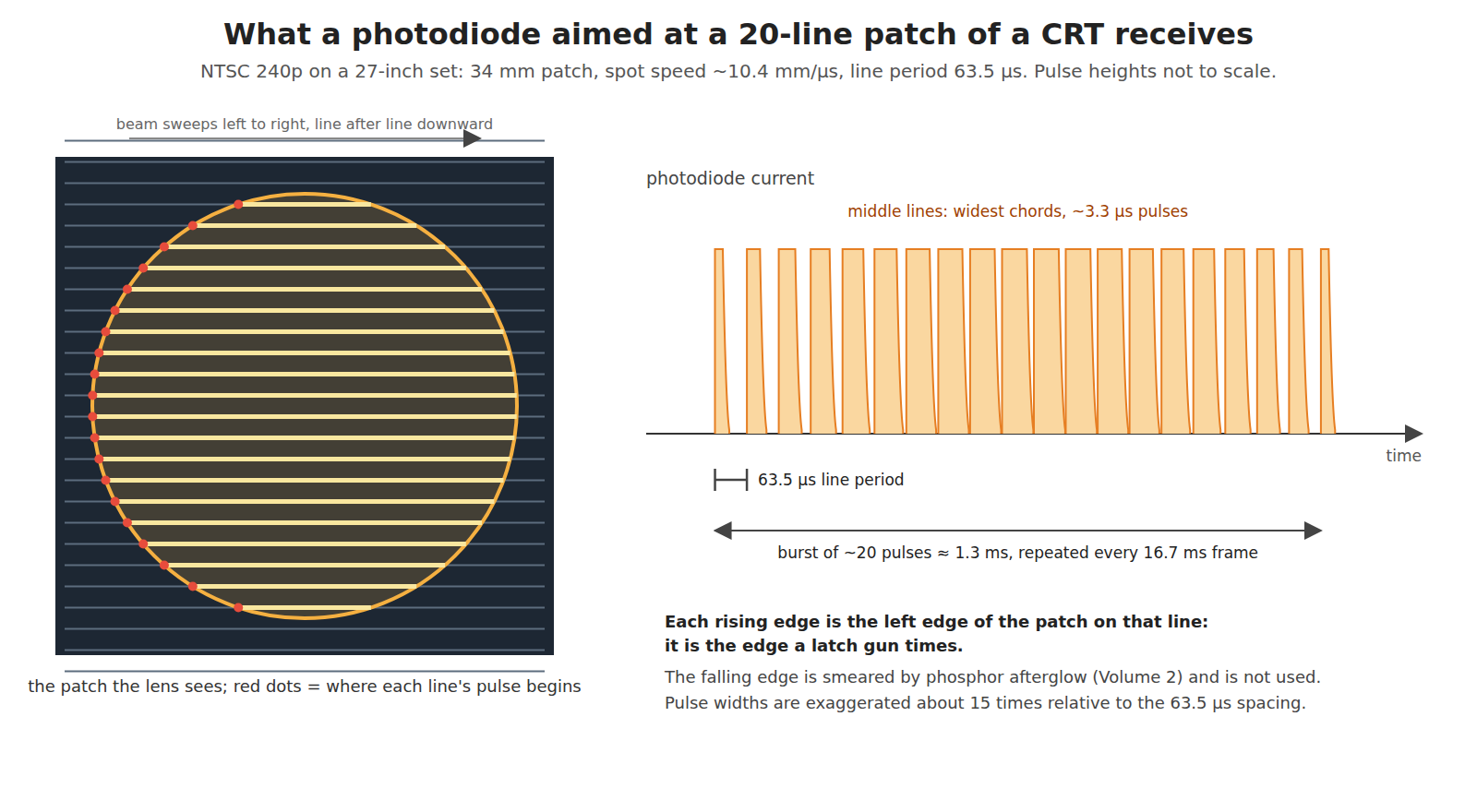
The gun does not see a point. Its lens images a small disc of the screen onto the photodiode. The SMS Power documentation of the Light Phaser says so directly: the sensor “sees a circular portion of the screen, and not a single pixel”.8 How big the disc is depends on the optics and the range; one useful published figure is Ben Ryves’s reading of Sega’s Menacer receiver design, which latches on the eighth line of light it sees, which he estimates “places the detected position roughly in the middle” of about 20 scan lines.9 Take a 20-line disc as the working example. On the 27-inch set that is about 34 mm across.
As the frame is drawn, the photodiode sees:
- Nothing, from vertical sync until the beam reaches the first line that crosses the disc.
- A pulse on each line that crosses the disc. Each pulse begins when the spot enters the disc and ends, apart from the phosphor’s afterglow, when it leaves. Across the middle of a 34 mm disc that is 34 mm ÷ 10.4 mm/µs, about 3.3 µs; near the top and bottom of the disc the chord is shorter and so is the pulse. The pulses repeat at the line period, 63.5 µs.
- Nothing again after the last line that crosses the disc, until the next frame.
So the signal is a burst of about 20 pulses, each a few microseconds wide, spaced 63.5 µs apart, lasting about 1.3 ms, once every 16.7 ms. The NESdev wiki’s measurements of the Zapper fit this: its light output stays on for “about 26 scanlines with pure white, 24 scanlines with light gray, or 19 lines with dark gray”, 1.2 to 1.7 ms.10
Three properties of this burst make it the most identifiable light in a living room, and every CRT gun relies on at least one of them:
- Its repetition rate is the line rate, about 15.7 kHz. No lamp has that. The Zapper’s filter is tuned to it (Volume 3).
- It happens at a known time. It is absent during vertical blanking. The GunCon reports light seen during vertical sync as an error, “eg. from a Bulb or Sunlight”.6
- It appears only when the program has made that part of the screen bright. That is the Zapper’s test frame (Volume 4).
The rising edge of each pulse is the useful part. It marks the moment the spot entered the disc on that line, which is the left edge of the disc. The falling edge is smeared by afterglow and is not used: the SMS Power documentation notes that the Master System’s hardware does not latch it at all.8 A latch gun therefore reports the left boundary of what it sees, and the game has to work out the centre (Volume 5).
1.7 Two ways to use the burst
There are only two ways a CRT gun has ever used the burst, and History of Light Guns, Volume 3 names them as two schools:
Table 4 — There are only two ways a CRT gun has ever used the burst, and [History of Light Guns, Volume 3](/light-guns/history-and-hardware/history-of-light-guns/vol-3/) names them as two schools
| Flash-frame (target box) | Raster-position latch | |
|---|---|---|
| Question asked | ”Did the gun see light during this frame?" | "When, after sync, did the light arrive?” |
| What the screen shows | A black frame with a white box on each candidate target, one per frame | A bright frame (or bright targets) |
| What the hardware needs | One filtered light bit | A counter driven by the dot clock and a latch that freezes it on the light edge |
| Result | Hit or miss on a named target | X and Y coordinates |
| Timing that matters | Which frame | The microsecond within the line |
| Examples | NES Zapper; ZX Spectrum guns | Light Phaser, Super Scope, Menacer, Justifier, GunCon, every home-computer pen |
| This dive | Volume 4 | Volume 5 |
The flash-frame method needs timing only to the frame, about 17 ms. The latch method needs it to a fraction of a microsecond, more than four orders of magnitude finer. That difference decides which of them can be rescued on a modern display (Volume 7).
1.8 The error budget in one sentence
Any delay is harmless if it is constant; any variation in it is error, at about 10 mm per microsecond on a 27-inch screen. Between the beam striking the phosphor and the counter freezing there are phosphor rise, photodiode and amplifier response, threshold crossing, sometimes an infrared link and a second receiver, cables, and the synchronisation of the edge into the counter’s clock. Their sum may be several microseconds, and a calibration shot subtracts it. Nintendo made a calibration mode mandatory in every Super Scope game for this reason.7 What the calibration cannot subtract is the spread of that sum from shot to shot, which is the jitter. Volume 5 builds the budget term by term.
1.9 The rest of this dive
Table 5 — 1.9 The rest of this dive
| Vol | Subject |
|---|---|
| 2 | The phosphor: P22’s three materials, their rise and decay, what silicon sees of them, and why red is nearly invisible to a gun |
| 3 | The front end: optics and patch size, photodiode against phototransistor, transimpedance bandwidth, the line-rate filter, thresholds, and the classic guns’ circuits redrawn |
| 4 | Flash-frame detection: the Zapper method in timing detail, its frame budget, and the hybrid that gets Y from the scan line |
| 5 | Raster latching: counters and latches per console, quantisation, the jitter budget term by term, the left-edge bias and how the Menacer centred it |
| 6 | What breaks it: 480i interlace, 100 Hz and frame-buffered CRTs, line doublers, and LCD and OLED in numbers |
| 7 | What does and does not work: flash-frame on a lagging display, beam-racing CRT simulators on fast OLEDs, and the display a latch gun would need |
| 8 | The bench: measuring a CRT, a sensor and a classic gun with the Analog Discovery Pro ADP3450 |
1.10 What could not be verified
- The Master System’s and Mega Drive’s dot clocks were not read in a primary source for this dive. Charles MacDonald’s VDP documents give 342 dots per line but not the clock, so the table leaves those cells blank.
- The 20-line patch is an estimate (Ryves’s, from the Menacer design) used as a worked example. The real patch depends on each gun’s lens, sensor size and the range, and was not measured for any gun.
- The 27-inch geometry ignores overscan and the curvature of the face.
Sources
Footnotes
-
International Telecommunication Union, Recommendation ITU-R BT.470-6, Conventional Television Systems (11/1998), Table 1 and Table 1-1, https://www.itu.int/rec/R-REC-BT.470/, read 2026-10-19. ↩
-
NESdev Wiki, “NTSC video”, https://www.nesdev.org/wiki/NTSC_video, read 2026-10-19 via the Internet Archive. ↩ ↩2
-
Martin Korth (nocash), fullsnes, “SNES PPU Timers and Status” (OPHCT/OPVCT, STAT78) and “SNES Timing Oscillators”, https://problemkaputt.de/fullsnes.htm, read 2026-10-19. ↩ ↩2 ↩3
-
Charles MacDonald, “Sega Master System VDP documentation” (2002), section 11, “Display timing”, https://www.smspower.org/uploads/Development/msvdp-20021112.txt, read 2026-10-19 via the Internet Archive. ↩
-
Charles MacDonald, “Sega Genesis VDP documentation”, version 1.5f (2000), section 5, “HV Counter”, read 2026-10-19 via the Internet Archive copy of cgfm2.emuviews.com/txt/genvdp.txt. ↩
-
Martin Korth (nocash), PlayStation Specifications (psx-spx), “Controllers — Lightguns — Namco (GunCon)”, https://psx-spx.consoledev.net/controllersandmemorycards/, read 2026-10-19. ↩ ↩2
-
Nintendo of America, Super NES Development Manual, Book II, Section 4, “Super NES Super Scope”, and Book I, Software Submission Requirements item 12. Internet Archive item
SNESDevManual, read 2026-10-19. ↩ ↩2 -
SMS Power!, “Light Phaser” (Development), https://www.smspower.org/Development/LightPhaser, read 2026-10-19. ↩ ↩2
-
Ben Ryves, “Using a Master System Light Phaser in Mega Drive Menacer games”, journal entry, 18 March 2020, https://benryves.com/journal/date/2020/3, read 2026-10-19. ↩
-
NESdev Wiki, “Zapper”, https://www.nesdev.org/wiki/Zapper, read 2026-10-19 via the Internet Archive. ↩
Comments (0)