Reference Electronics · Volume 3
The IR Positioning Camera — Module, Bus, Mounting and Field of View
The DFRobot SEN0158 every guide names and nobody can buy from DFRobot, the Wii sensor kept as a bench stopgap, the PixArt PAJ7025R3 chosen for kits, and the arithmetic of seeing four dots
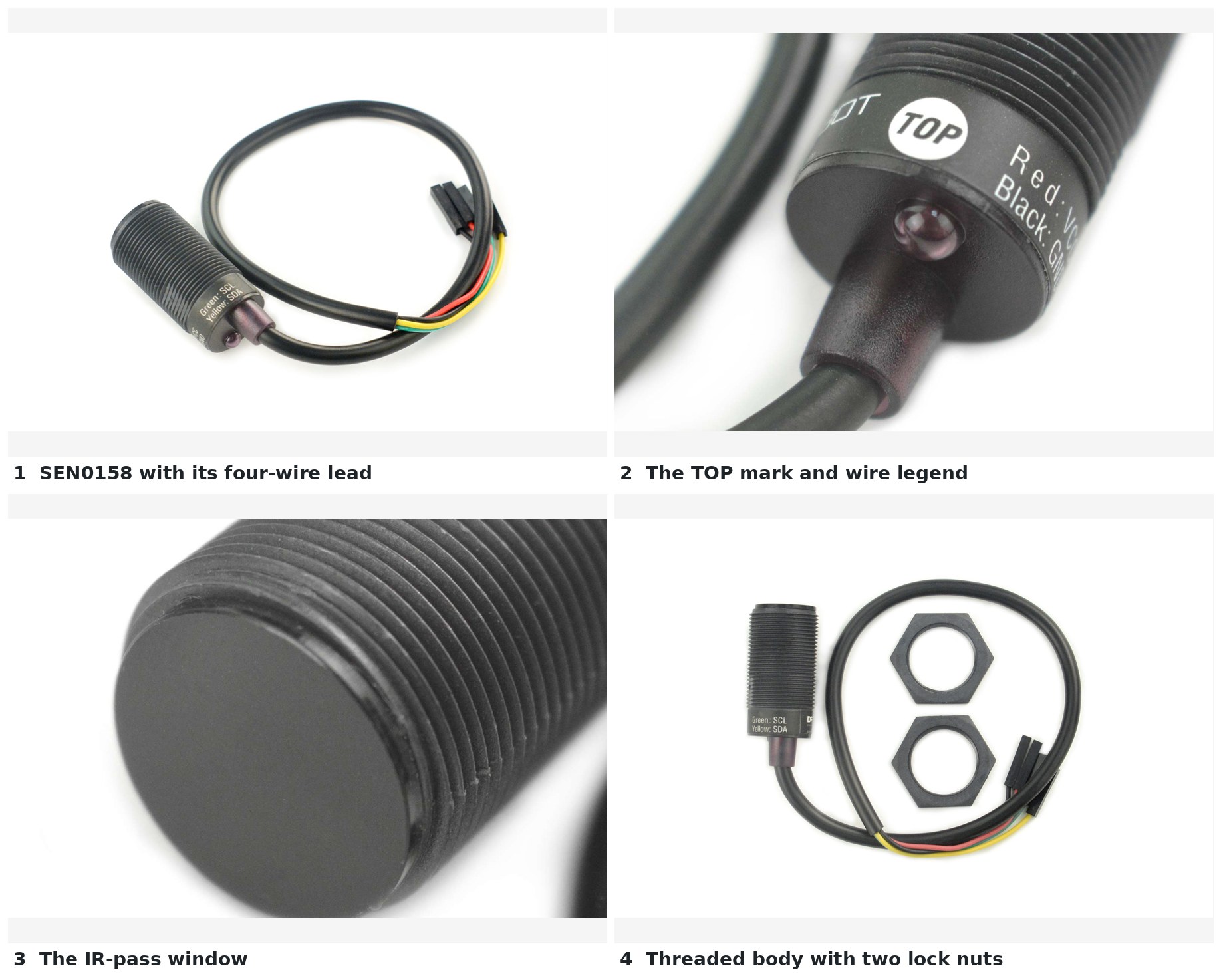
3.1 What the Camera Does
The camera in an IR light gun is not a camera in the usual sense. It does not deliver pixels. It is an image sensor with a hardware blob detector behind it: it finds the brightest infrared spots in its field of view and reports their coordinates over I2C. The microcontroller never sees an image, only up to four (x, y) pairs and, in the extended data format, a size for each.
DFRobot describes the SEN0158 as having a “Resolution is 128x96 pixel, with hardware image processing, which can track four objects (IR emitting or reflecting objects)”. The OpenFIRE library that reads it describes the same device as having “a resolution of 1024x768”; that figure is the coordinate range the sensor reports, exactly eight times the pixel count in each axis, so the sensor is evidently reporting positions to a fraction of a pixel. Both statements are true about different things, and the 1024 by 768 range is the one the firmware works in.
The sensor in the DFRobot module is the same class of device as the one in Nintendo’s Wii Remote. The OpenFIRE library’s sensitivity settings are taken straight from the WiiBrew wiki’s Wii Remote register notes, and the firmware’s hardware guide shows a bare sensor salvaged from a Wii Remote wired in its place (3.9). How the coordinates become an aim point is the business of the IR Point Tracking and Aiming Maths and Calibration dives.
3.2 The DFRobot SEN0158 in One Table
Table 1 — 3.2 The DFRobot SEN0158 in One Table
| Parameter | Value | Source |
|---|---|---|
| Name | Gravity: IR Positioning Camera For Arduino | DFRobot product page |
| Supply | ”Operating voltage: 3.3-5v” | DFRobot product page |
| Supply current | ”3.3V/44mA, 5V/48mA” | DFRobot wiki |
| Interface | I2C | DFRobot |
| I2C address | 0xB0 as an 8-bit write address; 0x58 in 7-bit form | OpenFIRE DFRobotIRPositionEx.h: IRAddress = 0xB0 >> 1 |
| Sensor | 128 × 96 pixels, hardware processing, four objects | DFRobot wiki |
| Reported coordinates | 1024 × 768; 1023 means not seen | OpenFIRE library README; DFRobot wiki (“returns 1023,1023”) |
| Field of view | 33° horizontal, 23° vertical | DFRobot product page |
| Detection distance | 0 to 3 m | DFRobot product page |
| Size | 32 × 16 mm, cylindrical | DFRobot |
| Lead | red VCC+, black GND, green SCL, yellow SDA | DFRobot wiki |
| Price | $23.55 | DFRobot product page, 2026-10-18 |
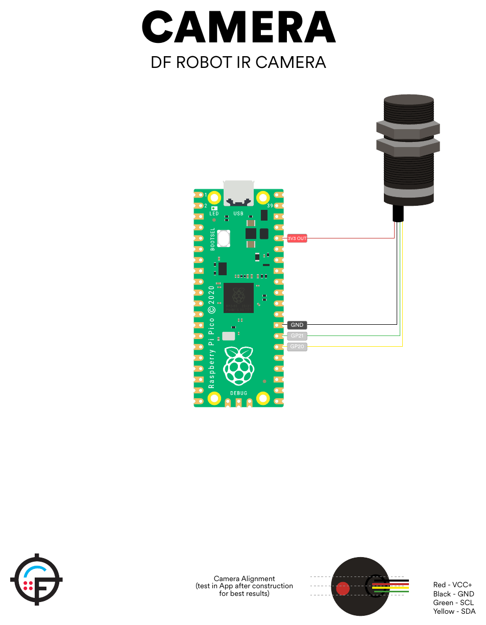
Two things are not published and matter for the board: whether the module carries its own I2C pull-up resistors, and whether it regulates its 5 V supply down internally or simply tolerates it. The firmware’s hardware guide powers it from the Pico’s 3V3 pin and shows no pull-ups. The reference design does the same and provides pull-up footprints (3.4). Both questions are on the bench list in Volume 7.
3.3 Availability
On 2026-10-18 DFRobot’s product page for SEN0158 showed the price, $23.55, but only a “Notify Me” button, with the notice “A new version of Gravity: IR Positioning Camera is currently in development and will be available soon.” No successor part number, date or specification has been published. The README of the OpenFIRE ESP32 port goes further: “The DFRobot SEN0158 is no longer made; a Wii camera can take its place”. Core Electronics, an Australian retailer, lists it as retired, and the Japanese distributor Switch Science is reported to mark it as ended. Some aggregators still list it as active and new-in-box units appear on eBay; Arrow, element14, RobotShop and Mouser refused automated reading on the day, so no distributor stock is recorded here.
Every OpenFIRE guide, including the firmware README’s requirements list and the PICON-AS parts list, still names this part. Switch Science lists it as “販売終了” (end of sale); a few distributor aggregators still call it “Active”, which DFRobot’s own page contradicts. That is why the camera was not assumed for this build (decision D3) but chosen by comparison, and why, once kits came into view, the comparison was rerun on a stricter rule (decision D18, 3.8): the camera has to be one that can be bought new, in quantity, with a datasheet.
3.4 The Bus: 1 MHz, Pull-Ups and the Cable
OpenFIRE’s board file sets the camera clock with a comment worth quoting whole:
// DFRobot IR camera IIC clock
// even with cheap clips and the full length IR cam cable 1MHz is fine
#define DFROBOT_IR_IIC_CLOCK 1000000
The library’s own header says the clock “Works up to at least 1MHz”, and its README reports that this was tested on a SAMD board. One megahertz is I2C Fast-mode Plus, and Fast-mode Plus has a 120 ns rise-time limit in the NXP I2C specification (UM10204). With a resistive pull-up the rise time is about 0.8473 × R × C, so the largest legal pull-up is set by the bus capacitance, most of which is the cable to the muzzle.
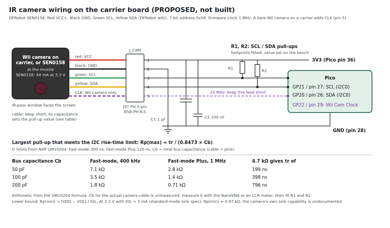
The table in the figure makes the point. At 100 pF of bus capacitance, a plausible figure for a lead of a few tens of centimetres plus two sets of pins, a 4.7 kΩ pull-up gives a rise time near 400 ns. That is outside the Fast-mode Plus limit and outside the 300 ns Fast-mode limit as well. The bus may still work, as the firmware comment says it does; I2C receivers are often forgiving and the clock high time stretches with a slow edge. But a design that works by tolerance is a design that fails in a long gun with a long cable.
The proposed approach:
- Measure the cable. The capacitance of the camera lead, from the board end, with the NanoVNA or an LCR meter (Volume 7).
- Count the pull-ups already there. The eatnooM Wii-camera carrier (3.9) fits 2.7 kΩ pull-ups of its own; whatever the carrier board adds is in parallel with them. Whether the SEN0158 has any is unknown (3.2).
- Fit pull-ups from the table. Start at 2.2 kΩ in total; drop toward 1.5 kΩ if the measured rise time is over 120 ns. The floor is set by the sink current of the weakest device on the bus: at 3.3 V and the standard 3 mA rating it is about 1 kΩ, and the camera’s own sink capability is not published.
- Look at the edge. The rise time of SCL with the Analog Discovery Pro ADP3450, measured at the camera end of the lead.
- Keep the lead away from the solenoid wiring. The two run the length of the gun in parallel if nobody prevents it.
The decoupling at the connector (1 µF plus 100 nF) is there because the camera draws its current in bursts as it processes frames, and the 3.3 V rail reaches it through the same lead.
3.5 The Update Rate and the Non-Atomic Read
The author of OpenFIRE’s camera library found something about this sensor that no datasheet records. With a test loop counting how often the position data changed, a slower I2C clock appeared to give a faster update rate: about 215 frames per second at 1 MHz and over 300 at 100 kHz. The explanation, in the library README: “The position data is not being reported atomically. In other words, the position data in the IR camera may update while reading the bytes over IIC.” A slow read is more likely to straddle an update and return a high byte from one frame and a low byte from the next. That also explained Y coordinates between 768 and 1023, which should not exist.
The library’s workaround reads the data repeatedly until two consecutive reads match, with at most three reads. With that in place, “the camera updates the position at ~209 times a second.”
For the hardware this has two consequences. A faster bus genuinely helps, because it shortens the window in which a read can straddle a frame. And the effective rate, about 209 per second, is the ceiling on aiming updates whatever the microcontroller; there is no point choosing a faster processor to read this camera faster.
3.6 Field of View, and How Far Back to Stand
A 33° by 23° field of view means a half-angle of 16.5° horizontally and 11.5° vertically. When the gun is aimed at one edge of the screen, the emitters at the far edge are a full screen-width away from the camera’s axis. For the camera to keep all four points in view while aiming at any point on the screen, the screen’s full width must fit within the half-angle. That sets a minimum distance of the screen width divided by tan 16.5°, and similarly for height.
Table 2 — 3.6 Field of View, and How Far Back to Stand
| Screen (16:9) | Width × height | Minimum distance, horizontal | Minimum distance, vertical |
|---|---|---|---|
| 24 in | 0.53 × 0.30 m | 1.8 m | 1.5 m |
| 32 in | 0.71 × 0.40 m | 2.4 m | 2.0 m |
| 43 in | 0.95 × 0.54 m | 3.2 m | 2.6 m |
| 55 in | 1.22 × 0.69 m | 4.1 m | 3.4 m |
| 65 in | 1.44 × 0.81 m | 4.9 m | 4.0 m |
The figures are arithmetic from DFRobot’s published field of view. They assume the camera’s axis is the aim axis and the emitters sit at the screen’s corners; emitters mounted outside the bezel make them slightly worse. Whether the firmware can keep tracking with one or two points out of view is a firmware question, treated in the Open-Source Firmware and IR Point Tracking dives. The table explains, though, why the community adds lenses. The PICON-AS parts list includes a clip-on phone wide-angle lens kit, GUN4IR’s mod kit includes a lens set and a printed camera-and-lens holder, and the PixArt PAJ7025R3 exists specifically as a wide-angle variant.
The table also sits awkwardly with DFRobot’s 0 to 3 m detection range. On a 55-inch television, the distance at which the narrow field of view stops being a problem is beyond the distance at which DFRobot rates the sensor to see the emitters at all. The usual resolution is brighter emitters (Volume 6) and a wider lens.
3.7 Mounting and Optical Alignment
The SEN0158 is a threaded cylinder with two lock nuts, which makes it a panel-mount part: a hole in a bulkhead at the muzzle, a nut each side. The thread size and pitch are not published.
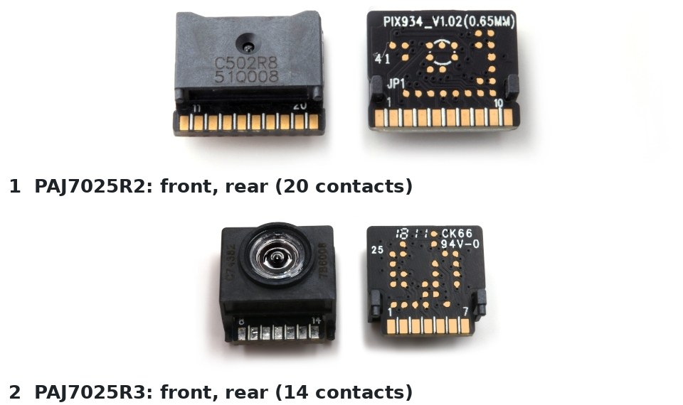
The kit camera mounts differently: the PAJ7025R3 is a 14-contact module that stands on the edge of a small breakout board, its lens looking along the board, located by two 0.8 mm posts (3.11, and the outline drawing in its datasheet). The bulkhead then holds the breakout rather than a threaded body. The alignment rules are the same.
Three alignment requirements follow from how the firmware uses the camera:
- Axis parallel to the bore line. The calibration routine maps camera coordinates to screen coordinates, so a fixed angular offset is calibrated out. A camera that can rotate or shift in its mount is not.
- Roll orientation fixed. The rear cap is marked TOP. The firmware’s hardware guide adds “Camera Alignment (test in App after construction for best results)”. A camera rolled a few degrees in its mount tilts the reported square of points, which the perspective tracking has to absorb.
- Rigid against the solenoid. The camera sits in the same structure that the solenoid hits several times a second. A mount that flexes under recoil moves the aim point for the duration of the kick.
The OpenFIRE app’s IR test mode displays the points as the camera sees them, which is the alignment tool. The firmware README describes it as “very useful for aligning the camera when building your light gun”.
3.8 The Candidates Compared
Decision (D18, 2026-10-18): the camera must be one that can be bought in quantity, because kits may be sold (D11). A camera harvested from a Wii Remote is acceptable as a bench stopgap only. That reopens the wave-2 choice, which had put a harvested Wii camera first. Every candidate that research turned up is below, with each figure attributed. “OpenFIRE” means the TeamOpenFIRE v6.2 firmware on an RP2040 or RP2350; “ESP32 port” means the community OpenFIRE-Firmware-ESP32, v7.0.0-rc5, a pre-release.
Table 3 — 3.8 The Candidates Compared
| Candidate | Interface | Sensor and output | Rate | Field of view | Wavelength | Firmware | Supply, price and lifecycle, 2026-10-18 |
|---|---|---|---|---|---|---|---|
| DFRobot SEN0158 | I2C, 0x58; 3.3 to 5 V, 44 mA at 3.3 V | 128 × 96, reports 1024 × 768, 4 points | about 209 per second (3.5) | 33° × 23° | works best at 940 nm | OpenFIRE: yes. ESP32 port: yes | $23.55 at DFRobot but “Notify Me”; retired at Core Electronics; “販売終了” (end of sale) at Switch Science |
| DFRobot successor | not published | not published | not published | not published | not published | unknown | ”in development and will be available soon”, unchanged; no part number or date |
| Wii Remote camera, harvested | I2C, same protocol; needs a 24 to 25 MHz clock | 128 × 96, 1024 × 768 by “8x subpixel analysis”, 4 points | as the SEN0158 | ”roughly 33° horizontal and 23° vertical”, one unit measured (WiiBrew) | 940 nm seen at about twice the intensity of 850 nm (WiiBrew) | OpenFIRE: yes, with the “Wii Cam Clock” pin. ESP32 port: yes | one per second-hand Wii Remote; no maker, no datasheet, no volume source. Third-party remotes may carry “different sensors with unknown pinout” (a builder’s report) |
| PixArt PAJ7025R2 | 4-wire SPI to 14 MHz; 2.0 to 3.6 V, 6 mA | 98 × 98 global shutter, up to 16 objects, 4095 × 4095 coordinates | up to 200 fps (PixArt) | “52.2°” diagonal (datasheet), so about 38° horizontal and vertical on its square array | 850 nm target (datasheet) | OpenFIRE: no. ESP32 port: yes (PixArt_PAJ7025 library) | in PixArt’s current catalogue; sample kit of 5, €70.00, CODICO GmbH, “Deliverable in short time”; production by quote, datasheet ordering table gives MOQ 900, tray |
| PixArt PAJ7025R3 | as R2; 14-contact module | as R2 | 200 fps (PixArt) | 142° ±5 % diagonal, 113° ±5 % horizontal and vertical (datasheet); “141”/“140 degrees” on PixArt’s page; 3 m working distance | IR filter passes 835 to 870 nm at over 85 %; 940 nm not specified | OpenFIRE: no. ESP32 port: yes, with a lens-distortion model the source calls “Theoretical … NOT a measured lens calibration” | in PixArt’s current catalogue; sample kit of 5, €70.00, CODICO GmbH; EPS Global by quote; WPG Americas out of stock, “8-32 weeks” |
| PixArt PAJ7620U2 | I2C or UART | 30 × 30, gesture and object motion | 360 Hz report rate | not stated; 20 to 30 cm operating distance | not stated | none | EPS Global |
| OV2640 “NV” camera on an ESP32-S3 (LIGHTGUN-STUDIO overlay) | parallel camera into an ESP32-S3 | general rolling-shutter camera, blob detection on the chip | not published | lens-dependent | 850 nm with an 800 nm long-pass filter, “recommended (non tested)“ | an MIT-licensed overlay for the ESP32 port, created 2026-08-22, “Please test” | camera modules widely sold; no lifecycle question, but no measured performance either |
| Global-shutter OV7251 / OV9281 class, blob detection on an MCU | MIPI or DVP | general camera | sensor-dependent | lens-dependent | any, with a filter | none found: a GitHub search for light-gun projects with either sensor returned nothing | not pursued |
| OpenMV Cam RT1062 | USB, SPI, I2C, UART | OV5640 general camera, blob detection in Python | ”about 40 FPS on QVGA” | lens-dependent | any, with a filter | none | $165.00, R6 on backorder (wave 2) |
| GUN4IR kit camera | not stated | ”a universal camera module” | not stated | not stated | not stated | GUN4IR; its builders’ adapter board is for a Wiimote camera (eatnooM, “for GUN4IR”) | in the €145.00 mod kits; every GUN4IR product “Sold out” |
Four things fall out of the table before any preference enters:
- Only PixArt sells a light-gun-class tracking camera today. The PAJ7025R2 and R3 are in PixArt’s current catalogue, are sold as samples by an authorised distributor, and come with a datasheet. Every Wii-class part is either out of production (the SEN0158), unannounced (its successor) or salvage (the Wii camera).
- Neither PixArt part has a distributor price at volume. The sample kit fixes the one-off price at €14 a sensor; 100 and 1,000 are a quotation from PixArt’s distributors (CODICO, EPS Global, WPG Americas), and the R2 datasheet’s ordering table states an MOQ of 900. That is a purchase to plan, not a click.
- There is no stocked source in the US. PixArt lists one distributor for the Americas, WPG Americas in San Jose; on 2026-10-19 its PAJ7025R3 page read “Currently Out of Stock”, with lead times of “8-32 weeks” and pricing on request, and it offered no sample kit. No DigiKey, Mouser, Arrow or LCSC listing was found. The sample kits come only from CODICO in Austria, which ships samples worldwide with no shipping charge, the buyer paying the import duty and card payment on delivery; its sample-shop terms, however, deliver “exclusively to entrepreneurs” (businesses), so a private buyer should ask CODICO before ordering (read 2026-10-24). For a US kit, the camera is a quotation through WPG Americas, placed months ahead of the kits that need it.
- The PixArt parts are a package deal: SPI wiring, 850 nm emitters (the R3 datasheet’s filter passes 835 to 870 nm; the SFH 4547 bar of Volume 6 is 940 nm), and firmware the stock image does not have (3.11).
- General cameras doing blob detection are a different design. The one working example found, an OV2640 overlay for the ESP32 port, publishes no frame rate or latency and is weeks old; no light-gun firmware or paper was found for a global-shutter sensor on a microcontroller. They are research for the Experimental Sensing dive, not a kit camera.
The datasheets carry a caveat of their own. Both PixArt datasheets read here (R3 version 1.0, 16 December 2016; R2 version 1.3, 21 November 2019) are watermarked “PixArt Confidential” and were found reproduced in a third-party KiCad library on GitHub. Their figures are quoted here because they decide the design, but they are not stored in the Library, and a kit maker needs its own copy from PixArt under PixArt’s terms. Hobbyists report that PixArt asks for a non-disclosure agreement first; the ESP32 port’s author records in a commit message of 2026-09-10 that his PAJ7025 drivers were “approvati da pixart” (approved by PixArt).
The arithmetic of the two lenses. The distance table of 3.6, extended to the PixArt parts by the same method (the screen’s full width within the half-angle):
Table 4 — The arithmetic of the two lenses. The distance table of 3.6, extended to the PixArt parts by the same method (the screen's full width within the half-angle)
| Screen (16:9) | Wii class, 33° | PAJ7025R2, about 38° | PAJ7025R3, 113° |
|---|---|---|---|
| 24 in | 1.8 m | 1.5 m | 0.35 m |
| 32 in | 2.4 m | 2.0 m | 0.5 m |
| 43 in | 3.2 m | 2.7 m | 0.6 m |
| 55 in | 4.1 m | 3.5 m | 0.8 m |
| 65 in | 4.9 m | 4.2 m | 1.0 m |
The R2’s “52.2°” is a diagonal on a square array, so its horizontal field is barely wider than the Wii camera’s; it does not solve the distance problem. The R3 does. Its cost is resolution: 98 pixels across 113° is about 1.15° a pixel, against about 0.39° for the R2 and 0.26° for the Wii camera. Across a 55-inch screen from 2.5 m, which spans about 27°, the R3 has about 24 pixels to work with, the R2 about 70 and the Wii camera about 106, before sub-pixel centroiding. How much aim jitter that costs is a bench measurement, not a datasheet figure.
3.9 Why This, and Why Not the Others
The criteria, in order (D18 and D11 first): can be bought new, with a datasheet, by the hundred, from a source that is still making it; sees four points from a normal living-room distance on a large television; has firmware or a port of firmware that exists; and fits a carrier board without changing the microcontroller if that can be avoided.
Kit camera: PixArt PAJ7025R3, read over SPI, with an 850 nm emitter bar. It is the only candidate that is in production with a datasheet and an authorised distributor, and of the two PixArt lenses it is the one that keeps four emitters in view at an ordinary distance from a large screen (the table above). The R2 is held as the bench comparison on the same connector and firmware, because the R3 pays for its field of view in pixels; if measured jitter at 2 to 3 m rules the R3 out, the R2 with a lens of its own is the fallback. Status: proposed, to be settled by that bench comparison.
Bench stopgap: a genuine Wii Remote camera on the eatnooM inline carrier, clocked from GP22, running stock OpenFIRE v6.2 on the Pico. It gets the first gun working this month while the PixArt firmware path (3.11) is done, and it is the camera every number in 3.4 to 3.7 describes. It is never the design camera.
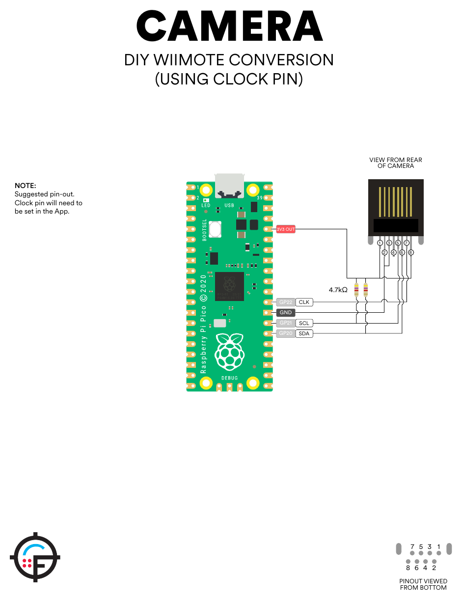
The stopgap in practice. The sensor needs an external clock. OpenFIRE provides one: if a pin is assigned to “Wii Cam Clock”, the firmware sets the system clock to 125 MHz and configures a PWM slice with a divider of 1, a wrap of 4 and a level of 2, which gives 25 MHz (125 MHz divided by 5) on that pin. WiiBrew gives the sensor’s clock as 24 MHz; the firmware’s 25 MHz is what its users run, and no source states the sensor’s tolerance. The hardware guide wires the clock to GP22 with two 4.7 kΩ pull-ups on SDA and SCL. A 25 MHz square wave on a wire inside a gun is an EMI source in its own right, so the clock lead must be short, which in practice means the Pico, or at least the clock pin, near the muzzle, or the oscillator fitted on the camera board.
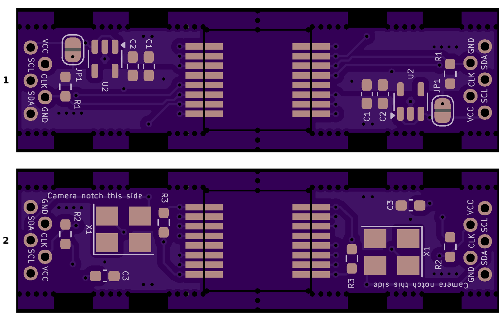
The eatnooM carrier’s page lists its parts: the camera (“Salvaged from an official Wiimote”), R1 and R2 at 2.7 kΩ, R3 at 33 kΩ, a 0.1 µF and two 1 µF capacitors, an AP2112-3.3 regulator and an optional 24 to 25 MHz SMD3225 oscillator (X1, a YXC or Kyocera part). It states that “OpenFIRE requires only R1, R2, R3 and the Wiimote camera itself”, which reads as: OpenFIRE supplies the clock, and with 3.3 V fed in directly the regulator is not needed, and it warns to “Order in 0.8mm thickness!” because otherwise the camera’s pads cannot be reached. An older version of the same board lists R3 as 330 kΩ; the current one’s README should be checked before ordering. Whether OpenFIRE works with X1 fitted and no clock pin assigned, which would keep 25 MHz off the long lead, is not stated anywhere and is a bench check (Volume 7).
A SEN0158, if one turns up, plugs into the same connector as the stopgap and needs no clock. It is not sought: buying a discontinued module from marketplace stock does nothing for a kit.
Table 5 — 3.9 Why This, and Why Not the Others
| Rejected | Why |
|---|---|
| Harvested Wii camera as the design camera | D18: salvage from second-hand remotes, no datasheet, no supply; clone remotes may carry other sensors |
| SEN0158 | out of production at its maker; aggregators’ “Active” status contradicts DFRobot’s own page |
| DFRobot successor | no part number, date or specification after the announcement |
| PAJ7025R2 as the kit camera | about 38° horizontal (its 52.2° is diagonal), so a 55-inch screen still needs 3.5 m; datasheet MOQ 900. Kept as the bench comparison |
| PAJ7620U2 | a gesture sensor: one object at 20 to 30 cm |
| OV2640 overlay on an ESP32-S3 | no published rate or latency; rolling shutter; weeks old and asking for testers |
| Global-shutter OV7251 / OV9281 on an MCU | no light-gun firmware or paper found; a new sensing method |
| OpenMV Cam RT1062 | $165, about 40 fps, no firmware support |
| GUN4IR kit camera | sold out, undocumented; its community adapter is for a Wiimote camera, so it is not a new part |
3.10 Where to Buy
Table 6 — 3.10 Where to Buy
| Item | Seller | Price (2026-10-18) | Notes |
|---|---|---|---|
| PixArt PAJ7025R3 sample kit, 5 sensors | CODICO GmbH, PAJ7025R3 Sample Kit (CDC) | €70.00 | ”Deliverable in short time”; bare modules, need a breakout PCB |
| PixArt PAJ7025R2 sample kit, 5 sensors | CODICO GmbH, PAJ7025R2 Sample Kit (CDC) | €70.00 | ”Deliverable in short time” |
| PixArt PAJ7025R3, production | EPS Global | by quotation | ”Quantity breaks available”; table not shown |
| PixArt PAJ7025R3, production | WPG Americas | by quotation | ”Currently Out of Stock”, “8-32 weeks” |
| PixArt, direct | PixArt PAJ7025R3 product page | ”Request of Quote” | the datasheet comes from PixArt |
| PAJ7025 KiCad symbol, footprint and breakout examples (R2 and R3) | alextrical/PAJ7025-KiCad-Library | free | a starting point for the Altium footprint; check against PixArt’s drawing |
| Wiimote IR Sensor carrier PCB, v1.2 (eatnooM), stopgap | OSH Park shared project | $4.50 total shown | order 0.8 mm thick |
| Wii Remote (donor, genuine Nintendo), stopgap | used market (eBay and similar) | not captured | stopgap only (D18) |
| DFRobot SEN0158 | DFRobot product 1088 | $23.55 | ”Notify Me”; not sought |
| GUN4IR Light Mod Kit (rejected, for reference) | GUN4IR | €145.00 | sold out |
| OpenMV Cam RT1062 (rejected, for reference) | OpenMV | $165.00 | R6 on backorder |
3.11 What the Kit Camera Changes
The firmware. TeamOpenFIRE v6.2 reads only the DFRobot/Wii camera. The PixArt driver exists in the ESP32 port: a library, PixArt_PAJ7025, under the GNU Lesser General Public License, whose own description reads “A cross-platform library (ESP32, RP2040) to easily interface with the PAJ7025 infrared camera via SPI”. It talks SPI mode 3, least-significant bit first, at 2 MHz by default, checks the product ID (0x7025) at start-up, and reads four objects with position, area and brightness. The port’s camera layer has a branch written for the RP2040 and RP2350, and its build file carries rpipico, rpipicow and rpipico2w environments next to the ESP32-S3 ones, but every release it has published is an ESP32-S3 image. So there are two routes, and neither is free:
- Keep the Pico; bring the driver into the fork. Port the LGPL library and the camera-model switch into the private OpenFIRE fork (D10), or build the ESP32 port itself for
rpipico. Either is untested on a Pico by anyone who has published a result. The ESP32 port’s Pico builds use the upstream Arduino-Pico 6.3.0 core, which the TeamOpenFIRE release toolchain avoids for a TinyUSB reason (Open-Source Firmware, OF-2), so that question comes with it. - Move the kit to the ESP32-S3. The port ships PixArt support today, plus the wireless link that D25 is trialling. The costs are those Volume 2 lists: a pre-release firmware, strapping and PSRAM pins, and ADC2 unusable with Wi-Fi.
So the kit camera does not force the ESP32-S3, but today only the ESP32-S3 port ships firmware for it. The proposal: the Stage 1 carrier stays on the Pico and runs the stopgap with stock firmware; it also carries an SPI camera connector (below), so route 1 can be tried on the same board; route 2 is settled by the D25 dongle trial. If the kit is to be wireless, route 2 wins on its own. Volume 2 carries the consequences for the pin budget.
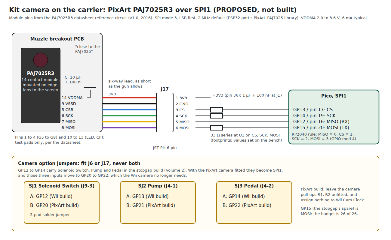
The pins. SPI on an RP2040 is not on any four pins. The port’s RP2040 branch enforces the chip’s function map: MISO on a GPIO whose number is 0 modulo 4, chip select on 1, clock on 2, MOSI on 3, all on the same controller. On the Pico the only block that fits the Stage 1 board is SPI1 on GP12 to GP15; Volume 2 shows the moves this forces.
The connector. A second camera connector, J17, six ways: 3V3, GND, CS, SCK, MISO, MOSI. The camera itself sits on a small breakout at the muzzle with the R3’s 14-contact footprint, the 10 µF and 100 nF the datasheet’s reference circuit places “close to the PAJ7025”, and the SPI series resistors. At 2 MHz over the camera lead SPI is undemanding, but it is four signals instead of two, and the clock edge is the part to look at with the ADP3450 (Volume 7).
The emitters. 850 nm, not 940 nm. Volume 6’s SFH 4547 bar suits the stopgap only; a kit bar needs an 850 nm LED, which is a change to that volume’s pick when the kit camera is confirmed.
The temperature. The R3 datasheet gives an operating range of 0 to 40 °C, absolute and recommended alike. A gun left in a hot car is outside it before it is switched on.
Sources
- DFRobot, Gravity: IR Positioning Camera For Arduino (SEN0158), product page, https://www.dfrobot.com/product-1088.html, and wiki, https://wiki.dfrobot.com/Positioning_ir_camera__SKU_SEN0158 (read 2026-10-18).
- TeamOpenFIRE, OpenFIRE-Firmware v6.2:
libraries/DFRobotIRPositionEx/(header and README),libraries/OpenFIREPosition/OpenFIREBoard.h,OpenFIREmain/OpenFIREcommon.cpp,OpenFIREmain/README.md. https://github.com/TeamOpenFIRE/OpenFIRE-Firmware (read 2026-10-18). - OpenFIRE Hardware Guide, version 1.2, camera pages. Hosted in https://github.com/alessandro-satanassi/OpenFIRE-Firmware-ESP32 at
lightgun/docs/guide/(read 2026-10-18). - Alessandro Satanassi, OpenFIRE-Firmware-ESP32:
lightgun/README.md,lightgun/platformio.ini,lightgun/lib/PixArt_PAJ7025/(header, source, library.properties and commit history),lightgun/src/OpenFIRECamera.cpp,lightgun/lib/OpenFIREPosition/OpenFIRECameraProfile.h; releases v7.0.0-rc3 to rc5 (read 2026-10-18). - NXP Semiconductors, UM10204, I2C-bus specification and user manual, rise-time limits and the pull-up sizing formula (Section 7.1).
- PixArt Imaging, PAJ7025R3 and PAJ7025R2 product pages, https://www.pixart.com/products-detail/46/ and https://www.pixart.com/products-detail/45/PAJ7025R2 (read 2026-10-18).
- PixArt Imaging, PAJ7025R3 Product Datasheet, version 1.0, 16 Dec 2016, and PAJ7025R2 Product Datasheet, version 1.3, 21 Nov 2019, both marked “PixArt Confidential”, as reproduced in alextrical/PAJ7025-KiCad-Library on GitHub (read 2026-10-18; not stored).
- CODICO GmbH, PAJ7025R3 Sample Kit (CDC) and PAJ7025R2 Sample Kit (CDC), shop pages on codico.com (read 2026-10-19; CODICO ships samples worldwide, the buyer paying import duty), with the GTC Sample Shop and Sample Order & Shipping pages (read 2026-10-24; delivery to businesses only).
- EPS Global and WPG Americas, PAJ7025R3 product pages (read 2026-10-18).
- Bart Trzynadlowski, PixArt (GitHub repository trzy/PixArt), README (read 2026-10-18).
- GUN4IR, New Light Mod Kit product page and store listing, https://gun4ir.com/collections/all (read 2026-10-18).
- WiiBrew wiki, Wiimote, IR camera section. https://wiibrew.org/wiki/Wiimote (read 2026-10-18).
- eatnooM, Wiimote IR Sensor - Inline (Panel) - v1.2, OSH Park shared project, and pixart-sensor-adapter (GitHub, CC-BY-SA-4.0) (read 2026-10-18).
- EPS Global, PAJ7620U2 product page; OpenMV, OpenMV Cam RT1062 product page (read 2026-10-18).
- frosted123456, LIGHTGUN-STUDIO-ESP32S3-OV2640 (GitHub, MIT), README (read 2026-10-18).
- Switch Science, product 5037 (SEN0158), and Core Electronics, Positioning IR Camera, retirement notices (search results, 2026-10-18).
Comments (0)