Reference Electronics · Volume 2
The Microcontroller Board — Pico, Pico 2 and the Alternatives
Which boards the firmware actually supports, the pin map it expects, the I2C and SPI pin rules, a silicon erratum that changes a pull-down resistor, and what to buy
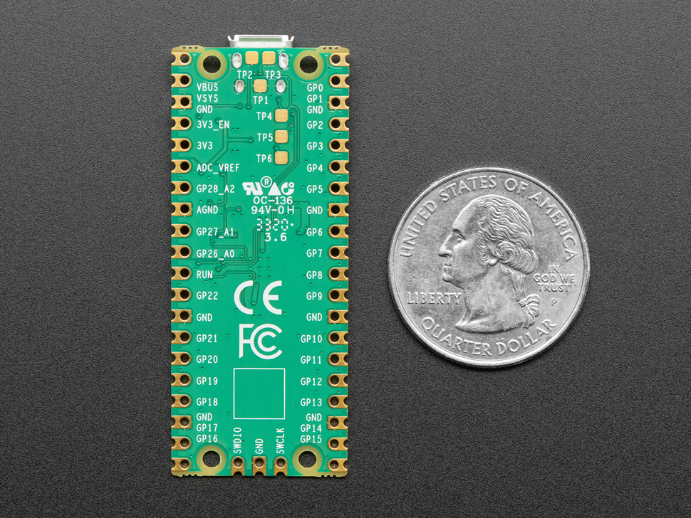
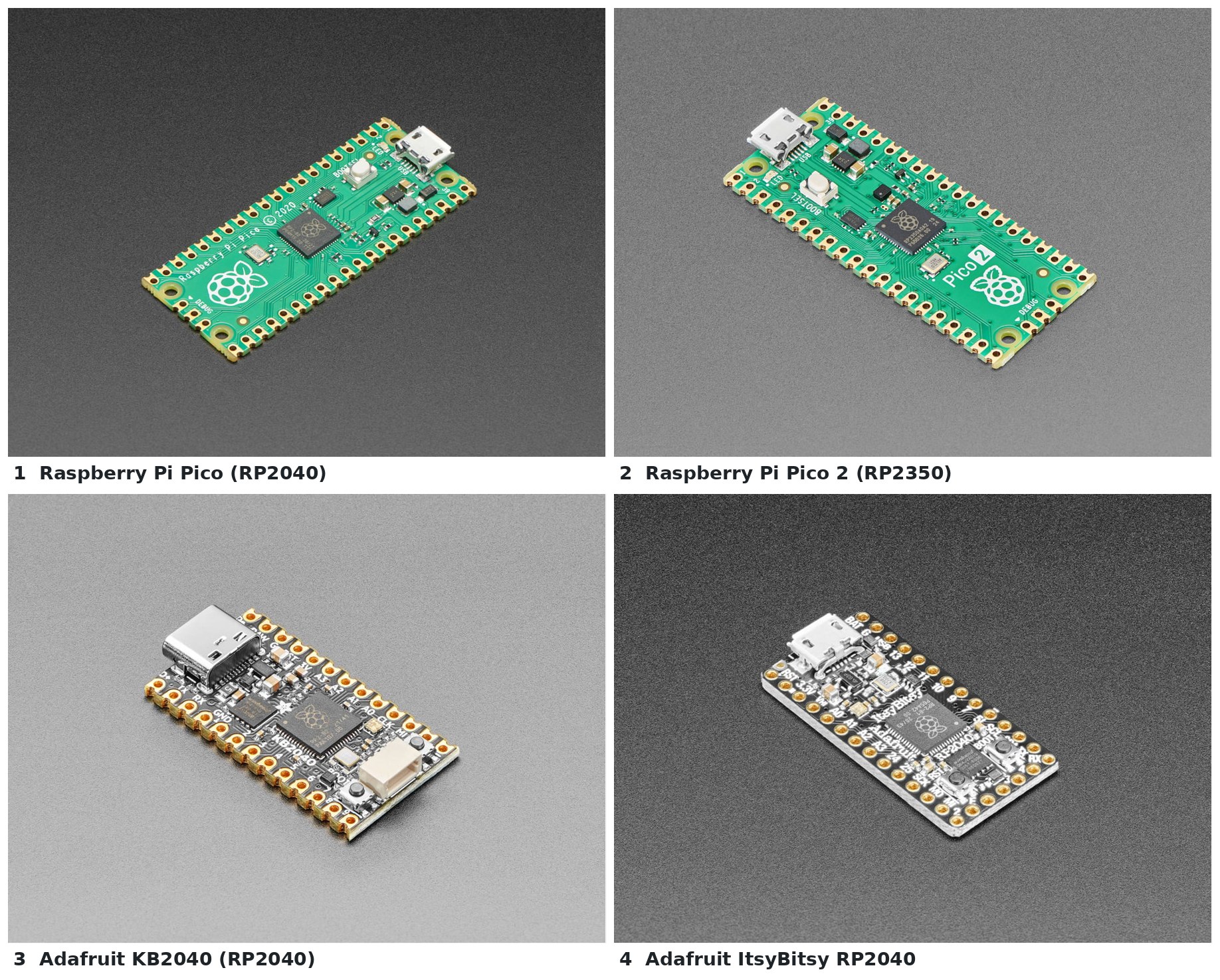
2.1 What the Board Has to Provide
The microcontroller board in a light gun does four things: it reads the camera over I2C a couple of hundred times a second, it scans a dozen or so switches, it switches two loads, and it presents itself to the host as a USB mouse, keyboard, gamepad and serial port at once. None of that is demanding by modern standards. What narrows the choice is the firmware: a board is useful here only if the firmware has an image for it, a default pin map for it, or at least a generic image and a pin map that the app can set.
For the reference design the requirements from Volume 1 reduce to:
- an RP2040 or RP2350 (R2: the stock OpenFIRE image runs on these and nothing else);
- 26 GPIO, three of them analog, for this build’s full list of functions (counted in 2.5);
- native USB;
- a 3.3 V output able to carry the camera (44 mA) with margin;
- a form factor that fits a gun receiver.
2.2 Which Boards the Firmware Supports
The TeamOpenFIRE release v6.2 (2026-04-19) ships these UF2 images: rpipico, rpipico2, rpipicow-noBT, rpipico2w-noBT, adafruitItsy, adafruitKB2040, arduinoNano, waveshareZero, vccgndYD, and two generic images, generic (RP2040) and generic_rp2350. The release notes say a board not on the list “may or may not work” with a generic image, “but you’ll have to map your controls manually”.
The -noBT suffix on the wireless Picos is deliberate. The firmware README lists a known issue: “With Pico W & Bluetooth enabled, TinyUSB/Serial fails to initialize properly when connected via USB”. For a wired gun the W boards offer nothing over the plain ones.
There is no ESP32 image from TeamOpenFIRE. The ESP32-S3 presets that appear in the shared board header (esp32-s3-devkitc-1, waveshare-esp32-s3-pico, and later waveshare-esp32-s3-zero) belong to a separate community port, OpenFIRE-Firmware-ESP32 by Alessandro Satanassi, whose latest release at the time of writing is v7.0.0-rc5 (2026-10-16), a pre-release. That port adds the ESP-NOW wireless link, a web configuration app and, notably, support for the PixArt PAJ7025 cameras (Volume 3). An earlier version of its README said that “the code still builds for the original RP2040 boards, but only for wired USB play”; that sentence is gone from the current README, but the build file still carries rpipico, rpipicow and rpipico2w environments beside the ESP32-S3 ones, and every published release is an ESP32-S3 image. That matters for the kit camera (2.5 and Volume 3, 3.11).
Table 1 — 2.2 Which Boards the Firmware Supports
| Board | MCU | Firmware | Default pin map | Notes for this build |
|---|---|---|---|---|
| Raspberry Pi Pico | RP2040 | OpenFIRE v6.2 rpipico | full (all functions) | the reference choice; most pins; 21 × 51 mm |
| Raspberry Pi Pico 2 | RP2350 | OpenFIRE v6.2 rpipico2 | identical to Pico | see erratum E9 (2.8) |
| Pico W / Pico 2 W | RP2040 / RP2350 | -noBT images | identical to Pico | no benefit for a wired gun |
| Adafruit KB2040 | RP2040 | adafruitKB2040 | partial: no pump, pedal, RGB or OLED pins by default | USB-C; Pro Micro footprint; 35.0 × 17.8 mm |
| Adafruit ItsyBitsy RP2040 | RP2040 | adafruitItsy | partial | fits SAMCO carrier boards; 36 × 18 mm |
| Waveshare RP2040-Zero | RP2040 | waveshareZero | trigger, A, B, C, Start, Select and camera only | very small; on-board LDO (ME6217C33M5G, “max current 800MA” per Waveshare) |
| Arduino Nano RP2040 Connect | RP2040 | arduinoNano | partial | some pins owned by the NINA Wi-Fi chip |
| VCC-GND YD RP2040 | RP2040 | vccgndYD | ”no default layout yet” (BOARDS.md) | a Pico clone with a NeoPixel |
| ESP32-S3-DevKitC-1 (N16R8) | ESP32-S3 | community ESP32 port | full, plus SPI camera pins | wireless-capable; large |
| Waveshare ESP32-S3-Pico / -Zero | ESP32-S3 | community ESP32 port | I2C camera only by default | wireless-capable; small |
A small discrepancy in the firmware’s own documents. For the Waveshare RP2040-Zero, BOARDS.md draws the camera on A0 and A1 (GP26 and GP27), while the machine-readable preset table that the firmware and app actually use puts camera SDA on GP14 and SCL on GP15. Both are legal I2C1 pairs. The table is what the firmware loads, so it wins; anyone wiring a Zero from the drawing will find the camera missing until the pins are changed in the app.
2.3 The Default Pin Map
The firmware’s BOARDS.md gives the Pico default as an ASCII drawing. The relevant lines, quoted:
                   A Button     0  |-)   *USB*   (-| VBUS (USB voltage)
                   B Button     1  |-)           (-| VSYS (Input from Battery/Output to NeoPixels)
                   ...
                   RGB Red     10  |-)           (-|  21 Camera SCL
                   RGB Green   11  |-)           (-|  20 Camera SDA
                   RGB Blue    12  |-)           (-|  19 Peripherals SCL
                   Pump Action 13  |-)           (-|  18 Peripherals SDA
                               GND |x)           (x| GND
                   Pedal       14  |-)           (-|  17 Rumble Signal
                   Trigger     15  |-)   _|_|_   (-|  16 Solenoid Signal
The file adds: “Any button/function GPIO pin assignments written here are the defaults, and can be changed for any other function from within the OpenFIRE App.”
The drawing is generated from a table, boardsPresetsMap, in the shared header OpenFIREshared.h. At the commit that firmware v6.2 pins, the Pico entry reads:
{"rpipico", {/*00*/ btnGunA,    btnGunB,     btnGunC,   btnStart,   btnSelect,
             /*05*/ btnHome,    btnGunUp,    btnGunDown, btnGunLeft, btnGunRight,
             /*10*/ ledR,       ledG,        ledB,      btnPump,    btnPedal,
             /*15*/ btnTrigger, solenoidPin, rumblePin, periphSDA,  periphSCL,
             /*20*/ camSDA,     camSCL,      btnUnmapped, unavailable, unavailable,
             /*25*/ unavailable, btnUnmapped, btnUnmapped, tempPin,  unavailable }},
(spacing condensed). The two agree. GP23 to GP25 and GP29 are marked unavailable because the Pico uses them internally (the regulator’s power-save pin, VBUS sense, the LED and VSYS sense). The rpipico2 entry is identical, with the note “Pico 2 boards are pin-identical to Pico 1 boards”.
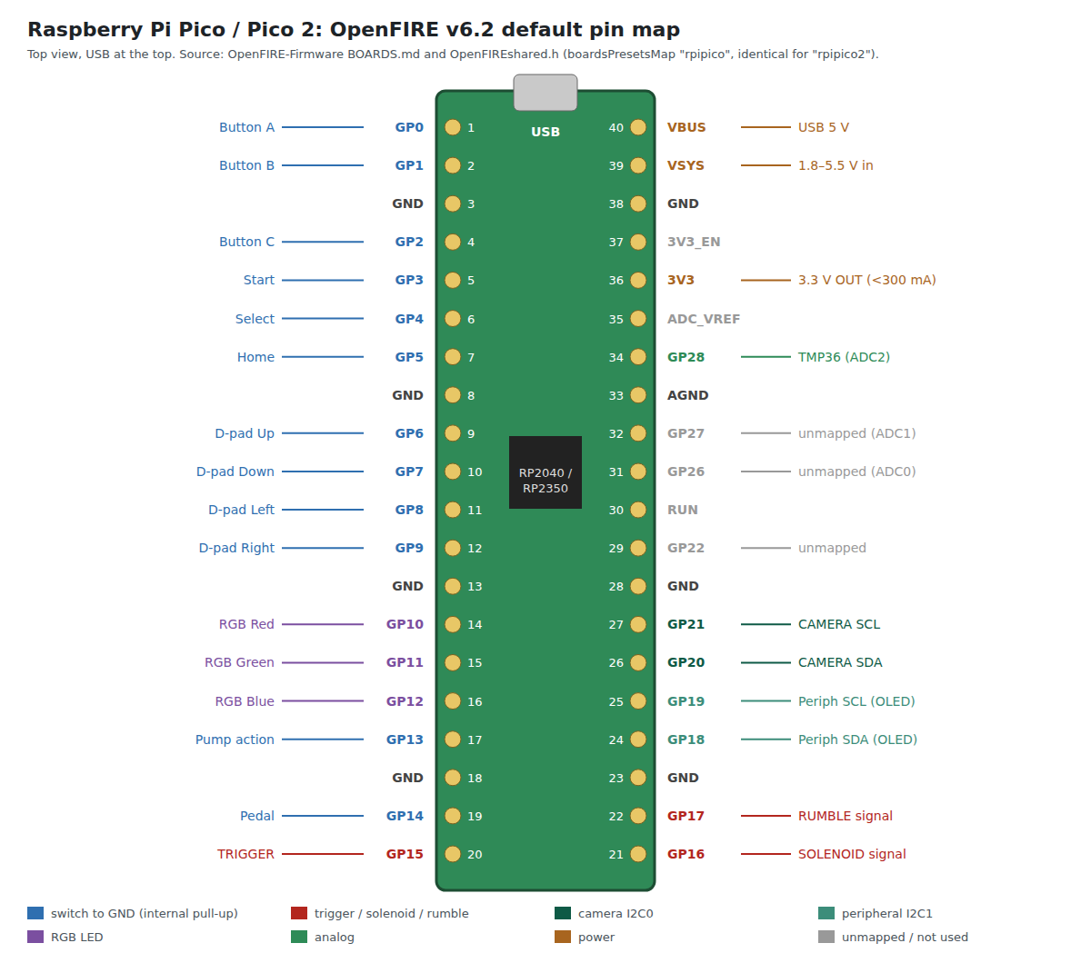
Two consequences for layout follow from the map. The two driver signals sit on pins 21 and 22, at the bottom corner of the right header, which is where the high-current section of a carrier board naturally goes. The camera pair sits on pins 26 and 27, next to them; on a carrier board the camera connector and the solenoid connector want to be at opposite ends, so these traces will cross the board. Volume 8 deals with that.
2.4 The I2C Pairing Rule
The RP2040 can route each of its two I2C controllers to several pin pairs, but not to arbitrary pins. The function that starts the camera in OpenFIRE (FW_Common::CameraSet() in OpenFIREcommon.cpp) checks the assignment before using it. It tests bit 1 of both pin numbers to decide whether they belong to I2C0 or I2C1, then requires bit 0 of the SCL pin to be 1 and bit 0 of the SDA pin to be 0. If either test fails the camera object is never created and the firmware reports an IR camera error.
In plain terms: SDA must be on an even GPIO and SCL on the next odd GPIO, and the pair must belong to one controller. The legal pairs on the RP2040 are:
Table 2 — In plain terms: SDA must be on an even GPIO and SCL on the next odd GPIO, and the pair must belong to one controller. The legal pairs on the RP2040 are
| Controller | SDA / SCL pairs (GPIO) |
|---|---|
| I2C0 | 0/1, 4/5, 8/9, 12/13, 16/17, 20/21, 24/25, 28/29 |
| I2C1 | 2/3, 6/7, 10/11, 14/15, 18/19, 22/23, 26/27 |
The camera and the peripheral bus must be on different controllers, which the defaults (I2C0 for the camera, I2C1 for the OLED) already arrange. If the Altium layout needs the camera elsewhere, any other pair from the I2C0 row will do, provided the pins are free and the app is told.
2.5 The Pin Budget
The decision for the first gun is a Raspberry Pi Pico (RP2040), with any other microcontroller acceptable only if it has enough inputs and outputs. “Enough” has to be counted, not assumed, because three choices made for this build add pins that the stock OpenFIRE map does not have: the trigger is a Hall-effect sensor read as an analog voltage (Volume 4), the moving ejection port may need its own power output (Volume 5), and a bare Wii Remote camera needs a clock pin (Volume 3).
The functions the gun needs, counted against the firmware’s own list of pin functions (boardInputs_Strings in OpenFIREshared.h):
Table 3 — The functions the gun needs, counted against the firmware's own list of pin functions (boardInputsStrings in OpenFIREshared.h)
| Function | Kind | Pins | OpenFIRE v6.2 function | Notes |
|---|---|---|---|---|
| Trigger, Hall-effect | analog in (ADC) or digital in | 1 (ADC) | “Trigger” is digital only | analog reading needs the fork (Volume 4) |
| Magazine release / reload | digital in | 1 | none; mapped to “Button C” | the firmware has no reload function; the game decides |
| Side buttons | digital in | 2 | ”Button A”, “Button B” | |
| D-pad | digital in | 4 | ”D-Pad Up/Down/Left/Right” | |
| Start, Select | digital in | 2 | ”Start”, “Select” | |
| Home / calibrate | digital in | 1 | ”Home Button” | |
| Pump action | digital in | 1 | ”Pump Action” | if the shell has one |
| Pedal | digital in | 1 | ”Pedal” | to a panel jack |
| Solenoid toggle | digital in | 1 | ”Solenoid Switch” | optional, recommended |
| Solenoid command | digital out | 1 | ”Solenoid Signal” | on/off |
| Rumble command | PWM out | 1 | ”Rumble Signal” | |
| Ejection-port actuator | digital out | 1 | none | only if the port gets its own actuator (decision D5); needs the fork |
| Status light | digital out | 1 or 3 | ”External NeoPixel” or “RGB LED Red/Green/Blue” | one NeoPixel saves two pins |
| IR camera, I2C | I2C pair | 2 | ”Camera SDA/SCL” | legal pair only (2.4) |
| Wii camera clock | 25 MHz out | 1 | ”Wii Cam Clock” | bare Wii sensor without its own oscillator |
| OLED, I2C | I2C pair | 2 | ”Peripherals SDA/SCL” | optional |
| Solenoid temperature | analog in (ADC) | 1 | ”Temperature Sensor” | TMP36 |
| Ejection-actuator temperature | analog in (ADC) | 1 | none | optional, fork |
With a NeoPixel for status and every option fitted that is 25 functions, 3 of them analog. The Pico exposes 26 user GPIO (GP0 to GP22 and GP26 to GP28), of which the last three are the only analog inputs a user can reach; GP29 is the fourth ADC channel but the Pico wires it to a VSYS divider.
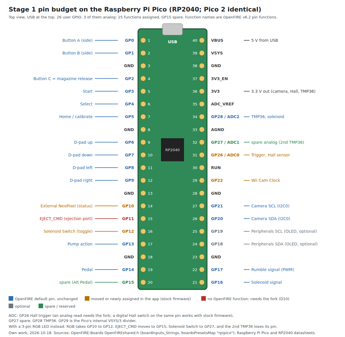
The proposed Stage 1 assignment (Volume 8 uses it):
Table 4 — The proposed Stage 1 assignment (Volume 8 uses it)
| GPIO | Function | Default? |
|---|---|---|
| GP0, GP1 | Button A, Button B (side buttons) | yes |
| GP2 | Button C, wired to the magazine release | default pin, new meaning |
| GP3, GP4, GP5 | Start, Select, Home | yes |
| GP6 to GP9 | D-pad | yes |
| GP10 | External NeoPixel (status) | moved from RGB red |
| GP11 | EJECT_CMD, ejection-port actuator | new; fork |
| GP12 | Solenoid Switch | moved from RGB blue |
| GP13, GP14 | Pump Action, Pedal | yes |
| GP15 | spare (Alt Pedal, or a digital Hall trigger in stock firmware) | freed from Trigger |
| GP16, GP17 | Solenoid Signal, Rumble Signal | yes |
| GP18, GP19 | Peripherals I2C (OLED, optional) | yes |
| GP20, GP21 | Camera SDA, SCL (I2C0) | yes |
| GP22 | Wii Cam Clock | assigned in the app |
| GP26 (ADC0) | Trigger, Hall sensor | moved from GP15 |
| GP27 (ADC1) | spare analog: ejection-actuator TMP36 | fork |
| GP28 (ADC2) | Temperature Sensor (TMP36) | yes |
Every pin is used or reserved, with GP15 the one spare. If a three-pin RGB LED is wanted instead of the NeoPixel, it takes GP10 to GP12 back, the ejection command moves to GP15 and the solenoid toggle to GP27, and something gives: the second TMP36 loses its pin. The budget is then over-full by one. Two things would break it: an analog thumbstick (two more ADC pins, and only one is spare) and a second I2C peripheral bus beyond the OLED. Either is the point at which the custom board (Volume 8, Stage 2) moves to a larger chip.
With the kit camera (decision D18). The camera chosen for kits, the PixArt PAJ7025R3 (Volume 3), talks SPI, not I2C, and needs four pins instead of the stopgap’s three (SDA, SCL and the Wii clock). On an RP2040, SPI pins must sit at fixed positions in the GPIO function map: MISO on a GPIO numbered 0 modulo 4, chip select on 1, clock on 2, MOSI on 3, all on one controller (the ESP32 port’s RP2040 code checks exactly this). The candidate blocks on the Pico are GP0 to GP3, GP4 to GP7, GP8 to GP11, GP12 to GP15, GP16 to GP19 and GP20 to GP23; GP23 is not brought out, and the others carry buttons, the D-pad, the NeoPixel, the drivers or the OLED. The least disruptive is SPI1 on GP12 to GP15: Solenoid Switch, Pump and Pedal move to GP20 to GP22, which the Wii camera frees, and GP15, the stopgap’s one spare, becomes MOSI.
Table 5 — 2.5 The Pin Budget
| GPIO | Stopgap build (Wii camera, stock firmware) | Kit-camera build (PAJ7025R3) |
|---|---|---|
| GP12 | Solenoid Switch | SPI1 MISO |
| GP13 | Pump Action | SPI1 CS |
| GP14 | Pedal | SPI1 SCK |
| GP15 | spare | SPI1 MOSI |
| GP20 | Camera SDA | Solenoid Switch |
| GP21 | Camera SCL | Pump Action |
| GP22 | Wii Cam Clock | Pedal |
That is 26 functions on 26 GPIO, with nothing spare. The carrier does it with three solder jumpers (Volume 3, 3.11; Volume 8). The RGB-LED variant then has no way to fit, and any further function (an analog stick, a second actuator’s sensor) pushes the design to an RP2350B or an ESP32-S3. On an ESP32-S3 the same list fits with pins to spare, which is one of the two arguments for route 2 in Volume 3, 3.11; the other is that its port already ships the PixArt driver.
Why the trigger is on GP26 rather than its default GP15. A Hall sensor read as a voltage needs an ADC pin, and GP26 to GP28 are the only ones. Putting it there from the first board means the same wiring serves both firmware paths: with stock OpenFIRE the app maps “Trigger” to GP26 and a digital Hall switch fitted to the same footprint works as a switch to ground; with the fork the same pin is read through the ADC (Volume 4).
The ADC itself. The RP2040’s ADC is 12-bit with an effective resolution of “8.7 ENOB” (RP2040 datasheet, 4.9.3) and samples at 500 ksps. Its erratum RP2040-E11, “DNL error peaks in ADC”, lists four codes (512, 1,536, 2,560 and 3,584) where the differential non-linearity peaks, with “Workaround None” and “Not fixed”. For a trigger that is a threshold on a smooth voltage, this matters only if a threshold is placed at one of those codes; Volume 4 keeps them clear. The RP2350 removed those spikes (“improving the ADC’s precision by around 0.5 ENOB”, RP2350 datasheet 12.4.1) and is rated “12-bit with 9.2 ENOB”.
2.6 Why This, and Why Not the Others
The criteria, in order: the stock firmware runs on it unmodified (so the fork stays optional); it has the pins counted in 2.5, including three ADC inputs; it can be bought; it fits a carrier board inside an MP7-size receiver; and its silicon has no erratum that the circuit cannot design out.
Table 6 — 2.6 Why This, and Why Not the Others
| Candidate | Firmware | GPIO / ADC available | Verdict |
|---|---|---|---|
| Raspberry Pi Pico (RP2040) | OpenFIRE v6.2 rpipico, full default map | 26 / 3 | Chosen (decision D2). Stock image; the firmware README calls it “cheapest, most pins available”; the budget fits with one pin spare. ADC erratum E11 is avoidable for a threshold. |
| Raspberry Pi Pico 2 (RP2350A) | rpipico2, identical map | 26 / 3 | Drop-in alternate, and the board to buy next (D19, 2.7). Better ADC (E11 fixed). Erratum E9 is fixed in the A4 stepping that Pico 2 boards moved to from July 2025 (2.8); older A2 stock may still be in the channel. In stock at SparkFun on 2026-10-18. The carrier is laid out to accept it. |
| RP2350B boards (QFN-80) | generic_rp2350 only, mapped by hand | 48 / 8 per the RP2350 datasheet | Rejected for now: no preset, more pins than needed, same E9 caveat. The obvious chip for the Stage 2 board if the budget overflows. |
| ESP32-S3 (DevKitC-1, Waveshare S3-Pico) | community ESP32 port only, v7.0.0-rc5, a pre-release | 45 programmable GPIO and 20 ADC channels on the chip (Espressif datasheet v2.2), fewer on a board | Rejected for the first gun: not the reference firmware, and the port is a release candidate. Its ADC2 channels “cannot be used with Wi-Fi simultaneously”; GPIO0, 3, 45 and 46 are strapping pins and GPIO33 to 37 belong to the octal PSRAM on N16R8 modules. Kept for the wireless builds (the D25 dongle trial) and as route 2 for the kit camera: its port is the only released firmware that reads the PAJ7025 (Volume 3, 3.11). |
| Adafruit KB2040, ItsyBitsy RP2040 | own images, partial maps | fewer pins broken out | Rejected: the KB2040 preset has no pump, pedal, RGB or OLED pins by default, and neither board breaks out all three ADC pins plus 23 digital ones. |
| Waveshare RP2040-Zero | waveshareZero, trigger, A, B, C, Start, Select and camera only | fewer pins broken out | Rejected: too few pins for this budget, and its own documents disagree on the camera pins (2.2). |
| Pico W / Pico 2 W | -noBT images | as Pico | Rejected: no benefit for a wired gun; the firmware’s own known issue with Bluetooth and USB. |
2.7 Pico or Pico 2
Table 7 — 2.7 Pico or Pico 2
| Pico (RP2040) | Pico 2 (RP2350) | |
|---|---|---|
| Cores | dual Cortex-M0+ | dual Cortex-M33 or dual Hazard3 RISC-V, 150 MHz (“Available now from $5”, Raspberry Pi) |
| SRAM / flash | 264 KB / 2 MB | 520 KB / 4 MB (Raspberry Pi product page) |
| Footprint and pin-out | 21 × 51 mm, 40 pins | identical |
| OpenFIRE image | rpipico | rpipico2 |
| Dual-core input handling | yes | the README says yes; a comment in OpenFIREDefines.h says “Currently exclusive to RP2040-based microcontrollers” (see text) |
| Pad erratum | none relevant | E9 on stepping A2 |
For this firmware the RP2040 is not a compromise. The camera itself limits the update rate to about 209 positions per second (Volume 3), and the RP2040 keeps up with it. The firmware’s documents disagree with each other on one point: the README says it is “Optimized for the RP2040 & RP2350, using its second core for input polling”, while the comment beside the DUAL_CORE switch says that feature is “Currently exclusive to RP2040-based microcontrollers”. The switch is tested against ARDUINO_ARCH_RP2040, a macro the Arduino-Pico core appears to define for both chips, so the comment may simply be stale; that has not been confirmed and is listed for the firmware dive. The Pico 2 is a drop-in alternative that buys headroom for a firmware fork, at the cost of one erratum that the hardware must accommodate.
Decision (D2, 2026-10-18): the first gun uses the Pico (RP2040). The carrier is laid out so that a Pico 2 drops into the same footprint without change, by meeting the erratum’s workaround regardless. The Pico 2’s better ADC (2.5) is the one argument for preferring it once the analog trigger is in the fork.
What to buy (decision D19, 2026-10-18: several Picos are on hand, and whatever is recommended will be bought). The recommendation:
Table 8 — What to buy (decision D19, 2026-10-18: several Picos are on hand, and whatever is recommended will be bought). The recommendation
| Buy | How many | Why | Why not the alternatives |
|---|---|---|---|
| Use the Picos on hand for the Stage 1 carrier and the stopgap camera | as many as the bench kills | stock rpipico image, full default map, the board the pin budget was counted on (D2) | nothing to gain by waiting for another board |
| Raspberry Pi Pico 2, A4 stepping | 3 | the same footprint and map; E9 fixed in A4 (2.8), so the 4.7 kΩ gate pull-downs become belt and braces rather than the only defence; the better ADC for the fork’s analog trigger; twice the SRAM for a fork that grows the PixArt driver | A2 stock: E9 live, and the Hall trigger and gates then depend on external parts alone. Check the marking on arrival: the part number ends A4 (A3 appears during the transition, per Raspberry Pi’s change notice) |
| One ESP32-S3-DevKitC-1, N16R8 | 1 (2 if the dongle trial needs its own) | the D25 wireless-dongle trial, and route 2 for the kit camera: the only board for which a released firmware reads the PAJ7025 (Volume 3, 3.11) | Waveshare ESP32-S3-Pico: maps only the I2C camera by default, SPI needs custom pins (the port’s README); a smaller board leaves less room for SPI, OLED and inputs |
| Pico W, Pico 2 W | none | no benefit for a wired gun; the firmware’s own Bluetooth/USB known issue | |
| RP2350B boards | none yet | only if the PixArt pin budget (2.5) has to grow; that is a Stage 2 question |
The ESP32 wireless dongle (decision D25). The trial of the ESP32 port’s ESP-NOW dongle bears on this choice in one way: if it succeeds and the kit is to be wireless, the kit’s microcontroller becomes an ESP32-S3 whatever the camera, and the PixArt firmware question answers itself. If it fails, or the kit stays wired, the Pico route with the PixArt driver brought into the fork remains the plan. Either way the Stage 1 carrier is a Pico board; an ESP32-S3 board is a separate carrier, laid out after the trial (Fully Wireless).
2.8 Erratum RP2350-E9 and the Gate Pull-Down
The RP2350 datasheet (build date 01/10/2026) documents an erratum titled “Increased leakage current on Bank 0 GPIO when pad input is enabled”, affecting stepping A2. Raspberry Pi’s product change notice PCN 32 (1 July 2025) moved the Pico 2, Pico 2 W, Pico 2 H and Pico 2 WH to the RP2350A A4 stepping and states “Errata 9 has been fixed, so any external circuitry used to work around this issue may need to be reviewed”; it adds that some boards are made with the intermediate A3 stepping during the transition, and that old and new units are in the distribution channel together. When a pad is configured as an input and its voltage sits in the undefined region between VIL and VIH, it “can source current … typically around 120μA. This leakage will hold the pad at around 2.2 V”. The datasheet goes on: “The pad pull-down (if enabled) is significantly weaker than the leakage current in this state and therefore isn’t strong enough to pull the pad voltage low.” Its workaround: “an external pull-down of 8.2 kΩ or less can be used.”
Pull-ups are unaffected, so the button inputs are safe. The analog trigger pin is safe too if the firmware does what the erratum itself says, “if ADC channels are being used on a pin, clear the relevant GPIO input enable”, and in any case the Hall sensor’s output is a low-impedance source (Volume 4). The concern is the solenoid gate.
Out of reset the problem does not arise; the datasheet notes that pull-downs work normally “immediately following a PoR or RUN reset because the input enable field is initially clear”. But OpenFIRE does not leave the driver pins as outputs for ever. In OpenFIREcommon.cpp, PinsReset() sets the solenoid and rumble pins to INPUT, and the serial handler calls PinsReset(), then CameraSet(), then FeedbackSet() (which makes them outputs again) whenever settings are saved from the app. For the duration of a camera restart, the gate node is an enabled input held only by external parts.
On an A2-stepping Pico 2 with the 100 kΩ gate pull-down drawn in the community hardware guide, the analysis says the pad would sit near 2.2 V for that interval. A logic-level MOSFET with a threshold between 1 and 2 V would be partly on, with the solenoid energised for as long as the camera takes to restart. This is an inference from the erratum text and the firmware source; it has not been observed on a bench. It is cheap to design out, so the reference design does:
- gate pull-down 4.7 kΩ, which satisfies the erratum’s 8.2 kΩ limit with margin and costs 0.7 mA while the output is high at 3.3 V;
- the same value on the rumble gate;
- in the gate-driver variant of Volume 5, the driver’s own input pull-down plus the same 4.7 kΩ.
The reference design keeps the 4.7 kΩ pull-downs on every board regardless: they cost nothing, they cover A2 stock still in the channel, and they define the gate when the Pico is unpowered (Volume 5).
The stepping is printed on the chip. Per the datasheet the part number is “RP2350”, the package letter, the package revision “0” and the die stepping “A2”, “A3” or “A4”, so an A2 part reads RP2350A0A2. Software can read CHIP_ID.REVISION (0x2 on A2); on A4 that register was reportedly not updated, and a Raspberry Pi engineer on the company forum recommends reading the boot ROM version, which picotool reports, instead. The marking on the package is the reliable check.
2.9 Powering the Board
The Pico datasheet describes the power path in a sentence: VBUS from the USB connector “is fed through a Schottky diode to generate VSYS”, and VSYS “feeds the RT6150 buck-boost SMPS, which generates a fixed 3.3 V output”. VSYS accepts 1.8 V to 5.5 V. Three points from it matter for the carrier board:
- The 3V3 pin can power external circuits, but “it is recommended to keep the load on this pin less than 300 mA”. The camera, TMP36, an OLED and an RGB LED come nowhere near that.
- VBUS is the right source for the rumble motor and NeoPixels. It is the 5 V from the host, before the diode. The firmware’s hardware guide runs both from VBUS.
- A second power source enters through VSYS, via a Schottky diode or a P-channel MOSFET in an OR arrangement, which the datasheet draws. That is the route a battery takes in the later wireless builds; the reference board leaves a footprint for it (R12).
GPIO23 on the Pico controls the regulator’s power-save pin. With it low (the default) the regulator runs in pulse-frequency mode at light load, which the datasheet notes gives more ripple. Setting it high selects PWM mode and is the usual cure for ADC noise. OpenFIRE reads the TMP36 on the ADC; whether its readings are noisy enough to need this is a bench question (Volume 7).
2.10 Module or Bare Chip
There are two ways to put an RP2040 on the gun’s own PCB.
Module on a carrier. The Pico is castellated and designed to be “usable as a surface mount module”, per its datasheet. Soldered flat onto a carrier, it brings its own regulator, crystal, flash and USB connector, and it uses the stock rpipico image. Its cost is board area: 21 by 51 mm, plus the micro-USB connector overhanging one end, which in a gun means the USB cable enters wherever the Pico’s end is.
Bare RP2040. The chip, a QSPI flash, a 12 MHz crystal, a regulator and a USB-C connector on the gun’s own board. This frees the layout entirely and allows USB-C at the stock of the gun. It also means the board is a “generic” RP2040 to the firmware, mapped by hand in the app, and that the USB, crystal and flash layout must be done properly. Raspberry Pi publishes a hardware design guide for exactly this, and the lab can assemble QFN parts with its reflow oven.
Decision (D7, 2026-10-18): a Pico on a carrier board first, a custom PCB in Altium later. The carrier is quicker to bring up, it uses the stock image, and a Pico that dies on the bench is replaced in minutes. The bare-chip board follows once the circuit has been proven. Volume 8 lays out both stages.
2.11 Where to Buy
Prices are as shown on each seller’s own page on 2026-10-18. DigiKey and Mouser refused automated reading that day, so their links are given without a captured price.
Table 9 — 2.11 Where to Buy
| Board | Seller | Price (2026-10-18) | Stock shown |
|---|---|---|---|
| Raspberry Pi Pico (RP2040) | Adafruit 4864 | $4.00 | out of stock |
| Raspberry Pi Pico 2 (RP2350) | Adafruit 6006 | $6.25 | out of stock |
| Raspberry Pi Pico 2 | SparkFun DEV-26124 | $5.75 | in stock; stepping not stated |
| ESP32-S3-DevKitC-1-N8R8 (port only) | Adafruit 5336 | $19.95 | out of stock |
| Raspberry Pi Pico 2 | Raspberry Pi product page | ”from $5” (list) | via approved resellers |
| Raspberry Pi Pico | DigiKey SC0915 | not captured | not captured |
| Adafruit KB2040 | Adafruit 5302 | $8.95 | in stock |
| Adafruit ItsyBitsy RP2040 | Adafruit 4888 | $9.95 | 64 in stock |
| Waveshare RP2040-Zero | Waveshare | $3.99 to $4.99 | not stated |
| Waveshare ESP32-S3-Pico (port only) | Waveshare | $8.99 to $9.99 | not stated |
| Waveshare ESP32-S3-Zero (port only) | Waveshare | $5.49 to $7.99 | not stated |
Two of the cheapest Pico listings were out of stock on the day; buying two or three boards at once is prudent, because the first one on a bench with a solenoid is the one most likely to die. The ESP32-S3 boards are listed for completeness; the ESP32 port’s README says to note “the exact board variant, for example N16R8”, because its installer is per-variant.
Sources
- TeamOpenFIRE, OpenFIRE-Firmware v6.2:
README.md,BOARDS.md,OpenFIREmain/OpenFIREDefines.h,OpenFIREmain/OpenFIREcommon.cpp,OpenFIREmain/OpenFIREserial.cpp; release notes and asset list for v6.2. https://github.com/TeamOpenFIRE/OpenFIRE-Firmware (read 2026-10-18). - TeamOpenFIRE, OpenFIRE-Boards,
OpenFIREshared.hat commit a019e91 and at HEAD. https://github.com/TeamOpenFIRE/OpenFIRE-Boards (read 2026-10-18). - Alessandro Satanassi, OpenFIRE-Firmware-ESP32,
README.mdandlightgun/README.md, v7.0.0-rc5. https://github.com/alessandro-satanassi/OpenFIRE-Firmware-ESP32 (read 2026-10-18). - Raspberry Pi Ltd, RP2350 Datasheet (build date 01/10/2026), Appendix D.5.1 “RP2350-E9”, section 14.4 “Package markings”, Appendix C. https://datasheets.raspberrypi.com/rp2350/rp2350-datasheet.pdf (read 2026-10-18).
- Raspberry Pi Ltd, RP2040 Datasheet, GPIO function table and PADS_BANK0 reset values. https://datasheets.raspberrypi.com/rp2040/rp2040-datasheet.pdf (read 2026-10-18).
- Raspberry Pi Ltd, Raspberry Pi Pico Datasheet and Pico 2 Datasheet, “Powering Pico” sections. https://datasheets.raspberrypi.com/ (read 2026-10-18).
- Raspberry Pi Ltd, Raspberry Pi Pico 2 product page. https://www.raspberrypi.com/products/raspberry-pi-pico-2/ (read 2026-10-18).
- OpenFIRE Hardware Guide, version 1.2 (PDF), hosted in the OpenFIRE-Firmware-ESP32 repository at
lightgun/docs/guide/. (read 2026-10-18). - Seller pages as linked in 2.11 (read 2026-10-18).
- Raspberry Pi Ltd, RP2040 Datasheet, section 4.9.3 “ADC ENOB” and erratum RP2040-E11 “DNL error peaks in ADC”; RP2350 Datasheet, Table 1 (package variants, GPIO and ADC counts) and section 12.4.1 “Changes from RP2040” (read 2026-10-18).
- Espressif Systems, ESP32-S3 Series Datasheet, version 2.2: feature list (GPIO, SAR ADC), strapping pins, section 4.2.2.1 SAR ADC note on ADC2 and Wi-Fi. https://www.espressif.com/sites/default/files/documentation/esp32-s3_datasheet_en.pdf (read 2026-10-18).
- Raspberry Pi Ltd, PCN 32 – Products moving to RP2350 A4 silicon stepping, release 1 (notification 1 July 2025). https://pip-assets.raspberrypi.com/categories/1262-pcn/documents/RP-008978-PC/Pico-2-Products-Moving-to-RP2350-A4-Silicon-Stepping (read 2026-10-18); Raspberry Pi news, “RP2350 A4, RP2354, and a new Hacking Challenge”, and the Raspberry Pi forum thread on
rp2350_chip_version()for A4 (search results, 2026-10-18). - Alessandro Satanassi, OpenFIRE-Firmware-ESP32,
lightgun/platformio.ini(rp2040 environments) andlightgun/src/OpenFIRECamera.cpp(RP2040 SPI pin rule) (read 2026-10-18).
Comments (0)