Reference Electronics · Volume 7
Breadboard Bring-Up — What to Measure, With What, and What Counts as a Pass
A staged plan for the first bench build: one electrical domain at a time, with the test points, instruments and pass criteria that turn this dive's open numbers into measured ones
7.1 Why Stage It
The brief this build started from says to flash the firmware first and bench-test the camera and recoil circuits on a breadboard before printing or soldering anything. That is right, and it can be taken one step further: wire one electrical domain at a time and do not add the next until the last has passed.
The reason is diagnostic. A light gun’s failures interact. A solenoid with a poor ground return resets the Pico; a reset looks like a camera fault; a noisy camera bus looks like a bad calibration. When everything is wired at once, every symptom has five candidate causes. When the domains arrive one at a time, each new symptom belongs to the thing just added.
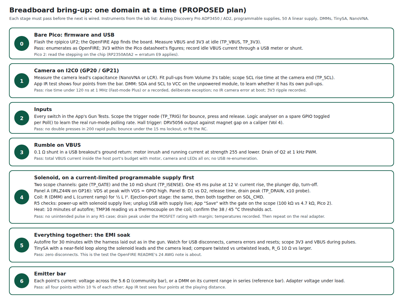
7.2 The Plan on One Page
7.3 The Bench
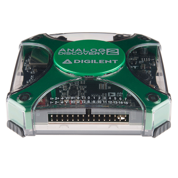
The lab’s electronics bench, as recorded in _shared/lab_capability.md, covers everything this plan needs.
Table 1 — 7.3 The Bench
| Job | Instrument | Used in stage |
|---|---|---|
| Gate, drain and shunt waveforms; I2C rise time; bounce | Analog Discovery Pro ADP3450 (or Analog Discovery 2) oscilloscope inputs | 1, 2, 4, 5 |
| Run-mode polling rate; I2C decode | the same instruments’ logic analyser | 1, 2 |
| Solenoid and ejection-port current | on the carrier’s regulated stage: TP_IPROPI (drive and brake), with the coast read from OUT2’s voltage; on the discrete breadboard stage: the 10 mΩ on-board R_S; on the Solenoid Recoil bench rig: that dive’s 0.1 Ω shunt | 4 |
| Hall trigger output against gap | ADP3450 voltmeter or a DMM, magnet on a caliper | 2 |
| Current-limited first power for the solenoid | one of the programmable supplies (USB- or Bluetooth-controlled) | 4 |
| Full-current solenoid supply with headroom | the 50 A linear supply | 4, 5 |
| Cable capacitance; coil inductance | NanoVNA (or an LCR meter, if one is on the bench) | 1, 4 |
| Radiated noise from leads | TinySA Ultra with a near-field loop | 5 |
| Resistances, LED currents, VDS | DMMs | 1, 4, 6 |
| Coil temperature reference | thermocouple on a DMM | 4 |
The ADP3450, as it bears on this plan. From Digilent’s specification sheet (ADP3450/ADP3250, rev 0924): four single-ended BNC oscilloscope inputs, 14-bit, “≥55 MHz” bandwidth, up to 125 MS/s per channel, 1 MΩ in parallel with 15 pF, and an input range of “±25 V with respect to ground” with overvoltage protection to ±50 V DC; buffers of up to 32 M samples per channel, cut to 32,768 samples in its stand-alone Linux mode; 16 digital channels (LVCMOS, 1.2 to 3.3 V, 5 V tolerant) that serve as logic analyser, pattern generator and I2C/SPI/UART protocol analyser at up to 125 MS/s; two waveform-generator channels; and one adjustable 1.2 to 3.3 V digital supply rated at 300 mA. Four things follow for this build:
- It has no current input, and its inputs are single-ended. Current is captured as the voltage across a shunt, and the shunt is placed where one end is ground. Two different shunts appear in this project, and they are not in conflict. R_S is a 10 mΩ on-board sense position (10 mV per amp) in the MOSFET’s source of the discrete stage (Volume 5, 5.4), the breadboard and fallback stage, and a 0 Ω link in service. The Solenoid Recoil dive’s 0.1 Ω shunt is a bench-rig part in the coil return of its own test fixture (SR-5), chosen for 100 mV per amp where nothing else is in the loop. Ten times the voltage is the right trade on a rig; a tenth of the loss is the right trade inside a gun. The carrier’s regulated stage has neither: its driver’s IPROPI pin gives 1.18 V per amp across R_IPROPI, read at TP_IPROPI, in drive and brake; in coast the current cannot be sensed there, but OUT2 sits at about V_SOL + 0.8 V until the current reaches zero, so the decay time is read from that voltage. At the 500 mV/div scales and below, the absolute resolution is 0.125 mV, about 12 mA through 10 mΩ. A high-side shunt would need two channels subtracted in a math channel, with the 12 or 24 V common mode eating the range; the board is laid out so that this is never necessary. For the USB current of stage 3, the shunt goes in the ground return of the USB breakout for the same reason. A clamp-on current probe with a BNC output would also work on one channel, but the low-side shunt makes it unnecessary.
- The drain node exceeds its range. On the discrete stage, a drain clamped by the SMBJ33A reaches about 53 V, beyond ±25 V and at the ±50 V protection limit. TP_DRAIN is probed with a ×10 probe, always. On the regulated stage, OUT1 and OUT2 swing between about −0.8 V and V_SOL + 0.8 V, so a ×10 probe there too once the rail is above about 24 V. The gate, the shunts and the logic nodes can use ×1 or ×10.
- It cannot power the gun. Its only supply is the 1.2 to 3.3 V, 300 mA digital rail. The solenoid comes from the programmable supplies and the 50 A supply, the logic from USB.
- Four channels is enough for one shot in full: gate, shunt (current), drain (×10) and TP_VSOL (rail sag) together, or, with the ejection-port stage fitted, the two shunts and two gates. The digital inputs take SOL_CMD, EJECT_CMD and the camera bus at the same time.
The programmable supplies (several, one Bluetooth-controlled and the rest USB-controlled; models not recorded) are what make stage 4 repeatable: a script can step the solenoid rail from 9 to 24 V and the current limit with it while the ADP3450 captures each shot.
The programmable supply’s current limit is the most important safety and diagnostic tool in stage 4. A first solenoid pulse into a breadboard with a wiring error is far kinder at a 1 A limit than on an adapter that will deliver its full rating into a short.
7.4 Test Points
The carrier board in Volume 8 exposes each of these as a pad or loop sized for a probe hook, reachable with the board installed in a shell where possible (requirement R10). On the breadboard they are the corresponding nodes.
Table 2 — 7.4 Test Points
| Test point | Node | What is measured there |
|---|---|---|
| TP_VBUS | USB 5 V at the carrier | supply under load; dips during solenoid pulses |
| TP_3V3 | Pico 3V3 out | ripple; dips |
| TP_GND (several) | logic ground; solenoid ground at the star | probe ground; ground offset between them |
| TP_SCL, TP_SDA | camera bus at the connector | rise time; decode |
| TP_SOLSIG | GP16 | the firmware’s command |
| TP_GATE | Q1 gate (discrete stage) or U4 IN1 (regulated) | drive level; behaviour on save and unplug |
| TP_DRAIN | Q1 drain, or U4 OUT2 | turn-off peak; clamp or coast voltage |
| TP_ISENSE | across R_S (discrete stage only) | solenoid current (10 mΩ: 10 mV per amp) |
| TP_IPROPI | IPROPI of U4 | solenoid current (750 Ω: 1.18 V per amp), drive and brake |
| TP_VREF | VREF of U4 | the current set point (VREF / 1.18 = I_TRIP in amps) |
| TP_VSOL | solenoid rail after C1 | rail sag during the pulse |
| TP_RUMBLE | Q2 drain | PWM, motor back-EMF |
| TP_TEMP | TMP36 output | compare with thermocouple |
| TP_IPROPI2, TP_OUT2B, TP_EJIN | the ejection-port stage (U5) | as for U4; TP_EJIN is U5’s input after the Q4 interlock |
| TP_TRIG | TRIG_HALL at U1 | Hall output: rest and full-pull voltage |
7.5 Stage by Stage
Stage 0: bare Pico. Flash the rpipico (or rpipico2) image, open the app, confirm the board is found. Record VBUS and 3V3 at idle and the idle USB current. On a Pico 2, read the chip marking; per the RP2350 datasheet’s package-marking section, the stepping is the last two characters of the part number, and RP2350A0A2 means erratum E9 applies (Volume 2).
Stage 1: camera. The stopgap Wii camera (or a SEN0158) comes first, on stock firmware; the PixArt kit camera follows once a firmware that reads it is running (Volume 3, 3.11), and repeats this stage on J17 with the SPI clock in place of SCL. Before connecting the stopgap camera, measure the capacitance of its lead from the board end. Choose pull-ups from the table in Volume 3, then confirm with a scope on SCL at the camera end: the rise time is the number that matters, and the Fast-mode Plus limit is 120 ns. With the module unpowered, measure from SDA and SCL to its VCC wire with a DMM; a few kilohms means it has its own pull-ups, which then appear in parallel with the board’s. Pass when the app’s IR test shows the four points of a bar with no IR camera error at boot.
For the harvested Wii camera (Volume 3), two more checks. The 25 MHz clock on GP22, seen at the camera end of its lead: amplitude and shape on a ×10 probe (at 55 MHz of bandwidth only the fundamental and the third harmonic survive, which is enough to see that it arrives) and, more usefully, the TinySA with a near-field loop along the lead, because this is the line most likely to radiate. And the oscillator question: fit X1 on the camera carrier, leave “Wii Cam Clock” unassigned in the app, and see whether the camera starts. If it does, the 25 MHz lead disappears from the gun.
Stage 2: inputs. Each switch in the app’s Gun Tests. Then a scope on the trigger node during a fast series of pulls, looking for bounce longer than the firmware’s 15 ms lockout (Volume 4). For the polling-rate question, a spare GPIO toggled once per Poll() call in a test build of the firmware and watched on the logic analyser gives the real run-mode rate; that is a firmware experiment and belongs to the Our Firmware dive if it needs a fork. The Hall trigger (Volume 4) is set up here with the real magnet before the shell is printed: the magnet on a caliper jaw, moved toward the sensor in 0.5 mm steps, with the DRV5056 output on the ADP3450’s voltmeter or a DMM at each step. Plot it against the computed curve in Volume 4; the difference is the shell-free error of the estimate. Then the same in the gun, with the real trigger blade, which gives the rest and full-pull counts that the fork’s calibration will find on its own. With the DRV5023 fitted instead, note the gap at which the output switches on the way in and back out.
Stage 3: rumble. A USB breakout with a 0.1 Ω shunt in its ground return (so that one single-ended ADP3450 channel reads it) gives the motor’s inrush and running current at strength 255 and lower settings. This is the number that decides whether the wired gun lives inside a USB port’s budget, because the motor, the Pico, the camera and any NeoPixels all draw from VBUS.
Stage 4: solenoid. The heart of the bring-up, in this order:
- First pulses on a programmable supply at 12 V with a current limit a little above the coil’s DC current (supply voltage over its measured resistance), then raised.
- Gate and shunt on two channels for one 45 ms pulse. The current ramp gives the coil’s inductance (L ≈ V / (dI/dt) at the start of the ramp); the dip in the ramp shows the plunger moving.
- For panel A of Volume 5 (IRLZ44N on GP16), the drain-source voltage at peak current with the gate at the GPIO’s high level. This is the measurement that qualifies or disqualifies direct drive for this solenoid.
- For panel B, the same, then the release with D1 fitted and with D2 fitted: drain peak, release time, and the solenoid’s feel. The energy check for D2, ½ L I² per shot, against the SMBJ33A’s rating.
- The regulated stage (Volume 5, decision D13). On the carrier: set VREF for 1 A and check the chop on TP_IPROPI; then step the set point to the coil’s target. Capture TP_IPROPI, TP_DRAIN (U4 OUT2, ×10) and TP_VSOL for one shot on a cold coil and on a hot one, and at 18, 24 and 28 V from a scripted programmable supply: the current should not move, which is the whole point of D13. Measure the chop frequency (estimated at 12 to 19 kHz, Volume 5) and listen for it. Measure the coast decay time at the end of the shot, from OUT2 falling back from V_SOL + 0.8 V, which the firmware needs for the D16 sequence, and the rise on TP_VSOL as the coil’s energy returns to C1. Plug the brick in live with the ADP3450 on TP_VSOL to check the DRV8251A’s 2 V/µs limit on VM.
- The ejection-port stage (decision D5) and the interlock (D16). Steps 1 to 5 again for that stage. Then the interlock: with a test build of the fork driving EJECT_CMD and SOL_CMD high together, TP_EJIN must stay low; and in the fork’s real sequence, TP_IPROPI and TP_IPROPI2 must never both show drive current at the same moment. The peak on TP_VSOL is then one stage’s, which is what the supply and fuse are sized for.
- The R5 cases from Volume 5: power up with the solenoid supply live; unplug USB with the supply live; and an app settings save with the gate on the scope, on a Pico 2 if one is available, with a 100 kΩ and then a 4.7 kΩ pull-down. This is the experiment that confirms or refutes the erratum E9 inference.
- Heat: ten minutes of autofire, comparing the TMP36’s reported temperature with a thermocouple on the coil, and confirming that the firmware’s warning (38 °C) and shutdown (45 °C) thresholds act. A printed shell softens long before an enamelled coil complains.
- Then the same on the real adapter, with the bulk capacitor fitted, watching TP_VSOL for sag.
Stage 5: the EMI soak. Everything wired as it will be in the gun, autofire for thirty minutes, watching for USB disconnects, camera errors and resets. The OpenFIRE README’s note about solenoid wiring and USB disconnects is a field report of exactly this failure. A near-field loop on the TinySA along the solenoid leads, compared with the leads twisted and untwisted and with R_G increased, shows what each change buys.
Stage 6: the emitter bar. The current in each point, and the adapter voltage under load. For a 5.6 Ω bar, the voltage across each resistor divided by 5.6 gives the current directly. Pass when the four points are within about ten percent of each other and the app’s IR test sees all four at the intended playing distance.
7.6 The Numbers This Dive Is Waiting For
In priority order, because each unblocks a design decision:
- Solenoid peak current and inductance, for the chosen solenoid on the 24 V-class rail (D14). Unblocks the current set point, the connector rating and the adapter size.
- The regulated stage’s chop frequency, coast decay time and audibility. Decides whether the DRV8251A stays or the discrete chopper (Volume 5) replaces it, and gives the firmware its D16 gap.
- VDS of an IRLZ44N at that current with 3.3 V on the gate. Decides whether the breadboard stage can stay in a first gun.
- Gate behaviour during an app save on a Pico 2. Confirms or refutes the E9 inference.
- Rumble motor current from VBUS. Decides whether the motor stays on USB power.
- Camera lead capacitance and SCL rise time. Sets R1 and R2.
- Whether the SEN0158 has on-board pull-ups. Sets R1 and R2 too.
- Emitter currents of the first bar. Calibrates the table in Volume 6 against reality.
- Run-mode polling rate. Settles how much the button filter actually filters.
- Hall output against gap, in the gun. Sets the magnet, the sensitivity version and the travel (Volume 4).
- Whether the Wii camera runs from its own oscillator. Decides whether a 25 MHz clock lead runs the length of the gun (Volume 3).
- The interlock and the sequence (D16). That the two stages never carry current at once, and the coast-decay gap the firmware must leave (Volume 5).
- The PixArt kit camera against the stopgap (D18). Aim jitter of the PAJ7025R3 and R2 at 2 to 3 m from a 55-inch screen, with an 850 nm bar, and the SPI clock edge at the camera end of the lead (Volume 3).
7.7 Safety at the Bench
- The solenoid moves. A push solenoid on a bench drives its plunger out hard enough to flick a small part across the room. Clamp it, or fit the return spring and stop, before the first pulse.
- Inductive kick. A coil disconnected while carrying current, by a breadboard wire pulled out mid-pulse, produces a spike with nothing to clamp it. Change wiring with the solenoid supply off.
- Current limit first. Stage 4’s first pulses are on a current-limited supply; the 50 A supply comes later and with its own limit set.
- Hot coils. A solenoid held on continuously, by a firmware fault or a stuck gate, reaches temperatures that burn skin and soften PLA. The firmware’s TMP36 cut-out protects the coil only if the sensor is fitted and its ground is right (Volume 4).
Sources
- TeamOpenFIRE, OpenFIRE-Firmware v6.2:
README.md,OpenFIREmain/README.md,OpenFIREmain/OpenFIREprefs.h,OpenFIREmain/OpenFIREFeedback.cpp(read 2026-10-18). - Raspberry Pi Ltd, RP2350 Datasheet (build date 01/10/2026), section 14.4 and erratum RP2350-E9 (read 2026-10-18).
- NXP Semiconductors, UM10204, I2C-bus specification and user manual, rise-time limits.
- The volumes of this dive cited at each stage, and
Firearms/_shared/lab_capability.md(2026-10-18) for the bench. - Digilent, Analog Discovery Pro (ADP3450/ADP3250) Specifications, rev 0924, copy hosted by TestEquity: https://assets.testequity.com/te1/Documents/pdf/Digilent_Analog-Discovery-Pro-ADP3450-ADP3250_Specifications_0924.pdf (read 2026-10-18; Digilent’s own pages refused automated reading).
Comments (0)