Reference Electronics · Volume 4
Inputs — Switches, a Hall-Effect Trigger, Debounce and the Harness
How a Hall-effect trigger, a dozen buttons and a temperature sensor are wired into a gun, what the firmware already does about bounce, which Hall sensor and magnet, and the low-power one that would make a trigger 200 ms late
4.1 Scope
This volume covers how an input is wired: the switch, the conductor, the connector and the pin. It does not cover which buttons a gun should have, where a thumb finds them, or what each one does in which game. That is the Controls and Inputs dive, not yet written. The firmware’s own hardware guide states the wiring rule for buttons in one line: “Buttons are all assigned internal pull-up resistors so no extra hardware is needed. Any momentary, normally open button will work.” Most of this volume is about the cases where that sentence is not quite enough.
4.2 What the Firmware Expects
OpenFIRE’s button library configures every mapped button pin with pinMode(pin, INPUT_PULLUP). A switch closes the pin to ground; a closed switch reads low. The same is true of the three optional hardware toggles (rumble, solenoid and autofire), which FeedbackSet() also sets to INPUT_PULLUP.
The input functions the firmware knows, from the boardInputs_Strings table in OpenFIREshared.h, are: Trigger, Button A, Button B, Button C, Start, Select, D-Pad Up, D-Pad Down, D-Pad Left, D-Pad Right, Pedal, Alt Pedal, Pump Action and Home Button, plus Rumble Switch, Solenoid Switch and Autofire Switch, and two analog inputs (Analog Stick X and Y). On the Pico map in Volume 2, every button has a default pin except Alt Pedal and the three toggles.
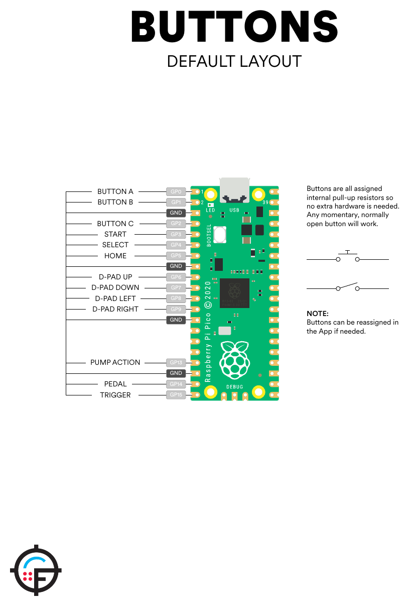
The RP2040’s internal pull-up is 50 to 80 kΩ according to its datasheet. That is weak. On a short lead it is fine. On a lead that runs the length of a gun, parallel to a solenoid lead switching amps, a 50 kΩ node is easy to disturb, and that is the case the optional parts below are for.
4.3 What the Firmware Does About Bounce
Reading the button library (LightgunButtons.cpp, v6.2) shows two mechanisms working together.
A sample filter. Each button has a 32-bit history. Every poll shifts the latest pin reading into it, and a change of state is accepted only when the history is all ones or all zeros under a mask. On RP2040 builds the mask is 0xFFFFFFFF (BTN_AG_MASK in OpenFIREBoard.h), so 32 consecutive identical readings are needed.
A time lockout. Once a change is accepted, the button is not read again for debounceTicks milliseconds, which in the default descriptor table in OpenFIREprefs.h is 15 for the trigger, A, B, C, Home, pump and pedals, and 20 for Start, Select and the four D-pad directions (Open-Source Firmware, Volume 6). (Corrected 2026-10-19; this said 15 for every button.)
How long the sample filter lasts depends on how often it runs. In the main loop’s menu paths the firmware calls Poll(1), which polls at most once per millisecond, so 32 samples take about 32 ms. In the run-mode loop on the second core it calls Poll(0), which polls on every pass; there the 32 samples take as long as 32 loop passes, which has not been measured. In run mode, then, a clean press is accepted quickly and the 15 ms lockout carries the burden of ignoring bounce.
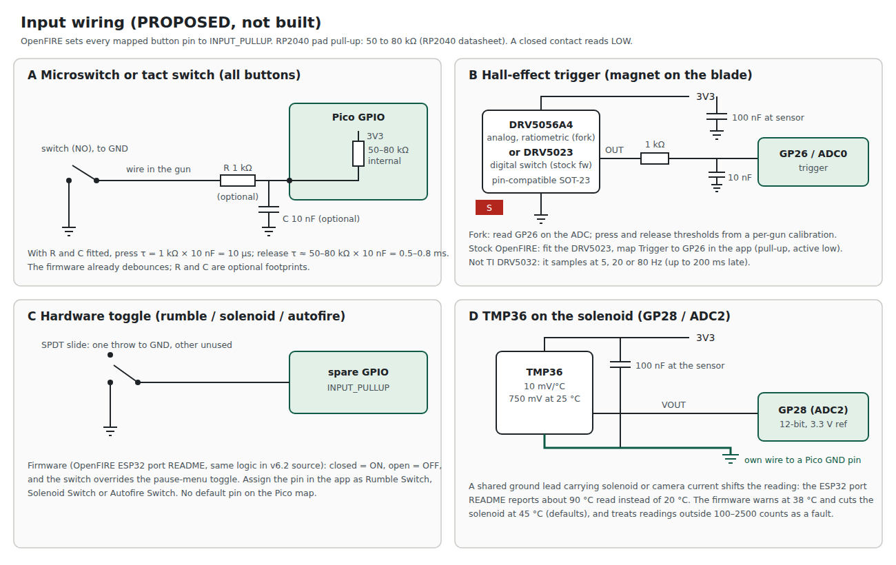
For the hardware, the conclusion is that contact bounce is handled in firmware, and that the failure mode to design against is bounce lasting longer than the 15 ms lockout. Controls and Inputs, Volume 3 adds a second hardware point: a microswitch’s contacts need a minimum load current that the Pico’s internal pull-up does not supply, so it proposes an external pull-up on every microswitch input (decision row CI-3). A worn or cheap switch, or a switch disturbed by solenoid recoil, could in principle register twice. The optional 1 kΩ and 10 nF in panel A of the figure below cost two footprints and remove that possibility; with the 50 to 80 kΩ internal pull-up they give a release time constant of about half a millisecond and a press time constant of 10 µs, both far below anything a player could notice.
4.4 The Wiring, Drawn
4.5 Switch Choices
Table 1 — 4.5 Switch Choices
| Switch | Where it suits | What to check |
|---|---|---|
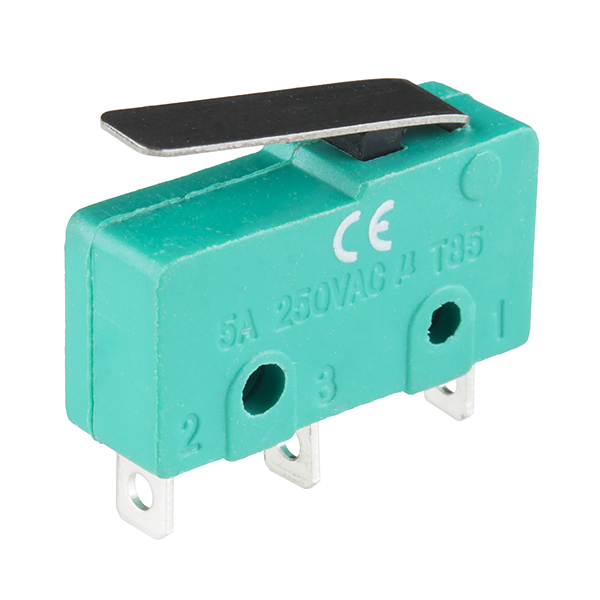
| Lever microswitch (subminiature, as in the photograph above) | pump, magazine release; the trigger in most other builds (this one is Hall-effect, 4.6) | operating force against the trigger spring; overtravel so the blade cannot crush it; mounting holes against the shell |
| 6 × 6 mm tact switch | A, B, C, Start, Select | actuator height through the shell; the PICON-AS list uses 6 × 6 × 5 mm for A, B and C |
| 5-way navigation switch | D-pad plus Home (centre press) | the ESP32 port README calls it “a 5-way navigation switch (Up, Down, Left, Right, and Centre, used as the Home button)“ |
| Microswitch in a foot pedal | Pedal, Alt Pedal | the lead length (metres), which is where panel A’s filter earns its place |
The PICON-AS build names a V-15-1C25 microswitch for its trigger. No manufacturer datasheet for a specific part number was read for this volume, so no operating force or contact rating is given here; those belong to the Controls and Inputs dive, which will choose switches by feel.
Two points apply to every switch in the gun:
- Use only common and normally open. A three-terminal microswitch’s normally closed contact is unused. The ESP32 port adds support for normally closed inputs; stock OpenFIRE v6.2 does not, as far as its button code shows.
- Signal-level contacts. A switch rated for mains current has a contact that may not wipe clean at microamps. For a 3.3 V, 50 µA circuit, a switch with gold-plated or “low level” contacts is the better choice where one is offered.
4.6 A Hall-Effect Trigger
Decision (D8, 2026-10-18): the trigger is Hall-effect from the first gun. A magnet on the trigger blade and a Hall sensor on the frame replace the contact. There is nothing to wear or bounce, and the break point is set by a number rather than by bending a microswitch lever. What was left open was the part, the magnet, the travel and how the firmware reads it. This section settles each, with the reasons.
4.6.1 Analog or digital
A Hall sensor can report a trigger in two ways.
- A digital switch (a unipolar Hall switch with an open-drain output) behaves exactly like a contact to ground. The firmware needs no change. But its operate and release points are fixed in the silicon, so the break point can only be moved mechanically.
- An analog (linear) sensor reports how far the trigger has travelled as a voltage. The break point, the reset point and the hysteresis between them become firmware settings, calibrated per gun, and the same hardware could later serve a two-stage or “analog” trigger.
OpenFIRE does not accept an analog trigger. The firmware’s complete list of pin functions (boardInputs_Strings in OpenFIREshared.h, v6.2) has exactly three analog entries: “Analog Stick X”, “Analog Stick Y” and “Temperature Sensor”. The trigger is a button, read with digital reads after INPUT_PULLUP like every other. The ESP32 port’s list is the same plus four SPI camera pins. Reading a linear Hall sensor is therefore a change in the fork (decision D10: bugs and features go into the project’s own fork for now), and is logged for the Our Firmware dive.
The board is designed so that this does not hold the first gun up. The analog sensor chosen below and the digital switch that would replace it are pin-for-pin compatible in SOT-23 (both TI datasheets: pin 1 VCC, pin 2 OUT, pin 3 GND), and the trigger’s output goes to GP26, an ADC pin (Volume 2’s pin budget). So:
- with stock OpenFIRE, fit the digital DRV5023 and map “Trigger” to GP26 in the app; the internal pull-up and active-low logic work as for any switch;
- with the fork, fit the analog DRV5056 and read GP26 through the ADC.
Panel B of the wiring sheet in 4.4 draws it.
4.6.2 The sensor: candidates and the pick
Table 2 — The sensor: candidates and the pick
| Candidate | Type | Supply | Output and speed | Verdict |
|---|---|---|---|---|
| TI DRV5056A4 | unipolar linear, ratiometric | 3.0 to 3.63 V or 4.5 to 5.5 V | 0.6 V at zero field, rising with a south pole; 15 mV/mT at 3.3 V, linear to 155 mT; 20 kHz bandwidth, 10 µs propagation delay | Chosen for the fork |
| TI DRV5056A3 (or A2, A8) | the same, more sensitive | as above | 30 mV/mT to 78 mT (A3) | Kept as the alternative if the shell forces a weaker magnet or a longer gap |
| TI DRV5023 | digital unipolar switch, open drain | 2.5 to 38 V | up to 30 kHz; “Fast 35-µs Power-On Time”; operate/release FA 3.5/2 mT, AJ 6.9/3.2 mT, BI 14.5/6 mT | Chosen for stock firmware, same footprint |
| TI DRV5055 | bipolar linear, ratiometric | as DRV5056 | VCC/2 at zero field | Rejected: a trigger magnet presents one pole, so half the output span (and of the ADC) is never used |
| TI DRV5032 | digital switch, duty-cycled | 1.65 to 5.5 V | samples at 80, 20 or 5 Hz | Rejected: up to 200 ms late (12.5 ms even at 80 Hz) |
| Allegro A1324 / A1325 / A1326 | linear, ratiometric | 4.5 to 5.5 V (datasheet) | 17 kHz bandwidth | Rejected: a 5 V part, whose output would exceed the RP2040’s 3.3 V ADC input without a divider |
| Honeywell SS49E | bipolar linear | 2.7 to 6.5 V per distributors | about 1.4 mV/G at 5 V per distributors | Rejected: bipolar (the DRV5055’s objection), and no manufacturer datasheet was read; the figures here are second-hand |
Why the DRV5056 over the others in one sentence each: it runs from the Pico’s own 3.3 V rail, which is also the ADC reference, so a supply that sags moves the sensor output and the ADC scale together (that is what “ratiometric” buys); its unipolar output puts the whole travel into the ADC’s range; and it shares a footprint with the digital part that stock firmware can use. Its costs are a supply current of 6 mA typical and 10 mA maximum (against microamps for a switch, which matters only on a battery) and a 150 µs power-on time.
Why A4 rather than a more sensitive version. The A4 is the least sensitive of the family, which is the right way round for a trigger: the magnet comes close at full pull, and a sensitive version would saturate early in the travel. The magnet arithmetic below shows the A4 using about 37 percent of the ADC’s range over a 5 mm travel without saturating. If the shell forces the magnet further away, the A3 doubles the sensitivity in the same footprint.
4.6.3 The magnet and its travel
The sensor sees flux perpendicular to the top of its package, and the DRV5056’s Hall element sits 650 µm (±80 µm) below the top of the SOT-23 (datasheet, Hall element location). The arrangement is therefore head-on: a small axially magnetised neodymium disc in a pocket in the trigger blade, south pole facing the sensor, moving straight toward the package top as the trigger is pulled.
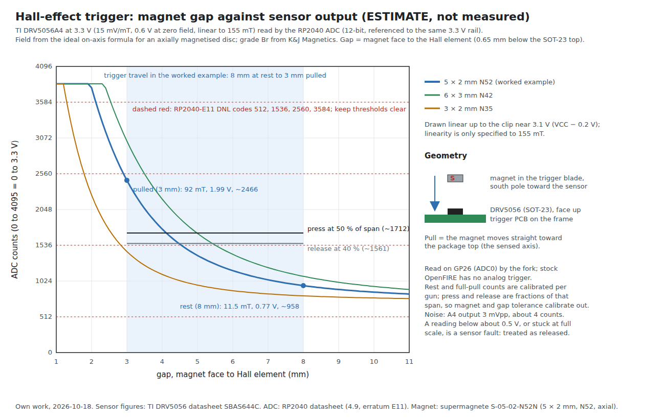
The figure’s numbers come from the standard on-axis field of an axially magnetised cylinder, B(z) = (Br/2)[(z+L)/√(R²+(z+L)²) − z/√(R²+z²)], with the grade’s remanence from K&J Magnetics’ table (N52 14.5 to 14.8 kG). For the worked example, a 5 by 2 mm N52 disc (supermagnete S-05-02-N52N):
Table 3 — The figure's numbers come from the standard on-axis field of an axially magnetised cylinder, B(z) = (Br/2)[(z+L)/√(R²+(z+L)²) − z/√(R²+z²)], with the grade's remanence from K&J Magnetics' table (N52 14.5 to 14.8 kG). For the worked example, a 5 by 2 mm N52 disc (supermagnete S-05-02-N52N)
| Gap to the element | Field (computed) | DRV5056A4 output | ADC counts |
|---|---|---|---|
| 8 mm (rest) | 11.5 mT | 0.77 V | about 958 |
| 5 mm | 35 mT | 1.12 V | about 1,390 |
| 4 mm | 55 mT | 1.43 V | about 1,770 |
| 3 mm (pulled) | 92 mT | 1.99 V | about 2,470 |
| 2 mm | 164 mT | beyond the 155 mT linear range |
These are estimates. The formula assumes the magnet is on the sensor’s axis, ignores tolerance and any steel in the shell, and the travel of 5 mm is a placeholder until the donor trigger is measured (MP7 Donor Build). The method is the point: pick the rest and full-pull gaps from the donor’s real travel, then pick the magnet and the sensitivity version so that full pull stays below the linear limit and rest stays well above the 0.6 V zero-field output. The magnet’s temperature drift is compensated inside the A-versions of the sensor (datasheet: “Compensation for magnet temperature drift”), and standard N-grade magnets are rated to 80 °C by K&J, comfortably above anything a trigger sees, though not above a solenoid coil: the magnet must not sit against the coil.
4.6.4 How it is read, calibrated and filtered (the fork)
- The pin. GP26 (ADC0). The RP2040’s ADC is 12-bit at 500 ksps, so a reading costs 2 µs; there is no reason to read it less often than the button loop runs. On a Pico 2, the erratum E9 text asks that the pin’s digital input be disabled when it is used as an ADC input, which the fork should do explicitly.
- The filter. A 1 kΩ series resistor and 10 nF to ground at the Pico: a 16 kHz pole that removes the sensor’s full-bandwidth noise (12 mVpp on the A2, 3 mVpp on the A4 per the datasheet) and gives the ADC’s sampling capacitor a local reservoir, while adding only 10 µs. The same parts are harmless for the digital DRV5023 with the internal pull-up (about 0.5 to 0.8 ms on release).
- Calibration. A menu step records the count at rest and at full pull and stores both. Press and release are then fractions of that span (the figure uses 50 and 40 percent), so magnet strength, gap and part-to-part sensitivity (±5 percent on the A4) calibrate out.
- Hysteresis. The 10 percent gap between press and release in the example is about 150 counts, against about 4 counts of noise. That margin is what keeps a trigger held near the break point from chattering.
- The ADC’s own fault. The RP2040’s erratum RP2040-E11 puts DNL spikes at codes 512, 1,536, 2,560 and 3,584. A threshold that lands within a few counts of one of those should be nudged; in the example the release point (about 1,561) sits 25 counts above 1,536, close enough to check. The Pico 2’s RP2350 does not have this erratum.
- Faults. A reading below about 0.5 V (the DRV5056’s zero-field output is 0.535 V at minimum) or pinned at full scale means a disconnected or failed sensor, and is treated as “not pressed”, never as a held trigger.
- Drift. While the trigger reads below the release threshold, the rest count can follow slow drift.
4.6.5 Latency, compared
The DRV5056’s propagation delay is 10 µs and its bandwidth 20 kHz; the RC filter adds 10 µs and the ADC 2 µs. These are microseconds, and the firmware’s own input handling (4.3) is the larger term either way. A Hall trigger read this way costs nothing worth counting in latency, which is the opposite of the DRV5032 trap.
4.7 Hardware Toggles and the TMP36
Toggles. OpenFIRE lets three functions be controlled by physical switches instead of the pause menu. The ESP32 port’s README describes the behaviour (the same input code is in the v6.2 source): “Wire each switch between its pin and GND … closed is on, open is off, and the switch has priority over the pause menu.” On the Pico map none of the three has a default pin; any free GPIO can be assigned in the app. For a gun that will be handed to other people, a solenoid on/off switch is worth its space.
The TMP36. The temperature sensor is wired on the input side but exists for the solenoid, and it has one wiring rule that is easy to miss. The ESP32 port’s README reports that when the sensor shared a ground wire with other modules, “Current flowing through a shared ground wire makes the sensor read too high (for example about 90 °C instead of 20 °C).” That is the expected result of a few millivolts of ground drop on a sensor scaled at 10 mV/°C: the TMP36 datasheet gives that slope and 750 mV at 25 °C, so every 10 mV of ground offset is a degree. A 90 °C error is 700 mV of offset.
The firmware’s response to a high reading is to throttle and then stop the solenoid (defaults: warning at 38 °C, shutdown at 45 °C), so a bad ground does not damage anything; it simply makes the recoil stop working, which is harder to diagnose. The reference design runs a dedicated ground conductor from the sensor to the board, separate from the solenoid’s return, and decouples the sensor with 100 nF at its pins, as both the hardware guide and the ESP32 port recommend.
4.8 Connectors and the Harness
A gun is opened and closed many times during a build. Every off-board item therefore goes on a connector (requirement R9 in Volume 1), and the connector family is chosen by current.
Table 4 — 4.8 Connectors and the Harness
| Circuit | Conductors | Proposed connector (board side) | Rating | Notes |
|---|---|---|---|---|
| Camera, stopgap | 5 | JST PH, B5B-PH-K-S | 2 A per contact | 2.0 mm pitch; keyed; pin 5 is the Wii camera clock (Volume 3) |
| Camera, kit (SPI) | 6 | JST PH, B6B-PH-K-S | 2 A per contact | the PixArt PAJ7025R3; fit this or the five-way, never both (Volume 3, 3.11) |
| Trigger (Hall) | 3 | JST PH, B3B-PH-K-S | 2 A | VCC, OUT, GND; its own connector, so the trigger board can be swapped |
| Buttons A, B, C, Start, Select, Home | 6 plus ground | JST PH 8-pin or two 4-pins | 2 A | grouped by location in the shell |
| D-pad | 4 plus ground | JST PH 5-pin | 2 A | |
| Pump, pedal jack | 2 to 3 | JST PH | 2 A | the pedal goes to a panel jack |
| TMP36 (two) | 3 each | JST PH, B3B-PH-K-S | 2 A | dedicated ground (4.7); the second on the port actuator |
| Rumble motor | 2 | JST PH 2-pin | 2 A | |
| NeoPixel | 3 | JST PH 3-pin | 2 A | VBUS, data, ground |
| Solenoid | 2 | JST VH, B2P-VH | 10 A | 3.96 mm pitch; see Volume 5 |
| Ejection-port actuator | 2 | JST VH, B2P-VH | 10 A | the second power stage (Volume 5, decision D5) |
| Solenoid supply in | 2 | JST VH, B2P-VH, from the GX connector at the base plate | 10 A | one GX carries USB and 24 V into the gun (decision D31, Power Supplies Vol 6); the solenoid return has its own pin |
Why JST PH and VH, and not the others. The criteria were a positive latch (a gun is shaken by its own solenoid), keying, a current rating with margin for each circuit, hand-crimpable or pre-crimped leads that Michael can make up, and cheap stock. JST PH (2.0 mm) meets all of them for every signal circuit; JST VH (3.96 mm, 10 A per contact) is the same family’s answer for the solenoid. Rejected: plain 0.1 in Dupont headers, which have no latch; JST SH (1.0 mm), which is harder to crimp and smaller than the board needs; JST XH (2.5 mm, 3 A), which offers nothing over PH for signals and is not enough for the solenoid; and screw terminals, which loosen under vibration.
The current ratings are LCSC’s listings for the JST parts on 2026-10-18 (B4B-PH-K-S and B3B-PH-K-S at 2 A, B2P-VH at 10 A). The PICON-AS parts list warns against JST PH for its battery leads because they “can’t carry 7 A”; the same logic puts the solenoid on VH rather than PH.
Sources
- TeamOpenFIRE, OpenFIRE-Firmware v6.2:
libraries/LightgunButtons/LightgunButtons.cppand.h,OpenFIREmain/OpenFIREprefs.h,OpenFIREmain/OpenFIREcommon.cpp,OpenFIREmain/OpenFIREmain.ino,libraries/OpenFIREPosition/OpenFIREBoard.h. https://github.com/TeamOpenFIRE/OpenFIRE-Firmware (read 2026-10-18). - TeamOpenFIRE, OpenFIRE-Boards,
OpenFIREshared.hat commit a019e91 (read 2026-10-18). - OpenFIRE Hardware Guide, version 1.2, buttons and solenoid pages (read 2026-10-18).
- Alessandro Satanassi, OpenFIRE-Firmware-ESP32,
lightgun/README.md, v7.0.0-rc5 (read 2026-10-18). - Alessandro Satanassi, PICON-AS: Hardware & Wiring (read 2026-10-18).
- Raspberry Pi Ltd, RP2040 Datasheet, GPIO electrical characteristics (pull-up and pull-down resistance).
- Texas Instruments, DRV5023 and DRV5032 product pages, https://www.ti.com/product/DRV5023 and https://www.ti.com/product/DRV5032; DRV5023 datasheet (pin functions, power-on time) (read 2026-10-18).
- Analog Devices, TMP35/TMP36/TMP37 data sheet (read 2026-10-18).
- LCSC product pages for JST B4B-PH-K-S(LF)(SN) (C131334), B3B-PH-K-S(LF)(SN) (C131339) and B2P-VH(LF)(SN) (C160315) (read 2026-10-18).
- Texas Instruments, DRV5056 Unipolar Ratiometric Linear Hall Effect Sensor, SBAS644C (revised December 2025): electrical and magnetic characteristics, pin functions, Hall element location. https://www.ti.com/lit/ds/symlink/drv5056.pdf (read 2026-10-18).
- Texas Instruments, DRV5055 product page and datasheet (pin functions, quiescent output) (read 2026-10-18).
- Allegro MicroSystems, A1324, A1325, and A1326 datasheet, operating characteristics (read 2026-10-18).
- TeamOpenFIRE, OpenFIRE-Boards
OpenFIREshared.hat commit a019e91,boardInputs_Strings; and the ESP32 port’slightgun/src/boards/OpenFIREshared.h(read 2026-10-18). - Raspberry Pi Ltd, RP2040 Datasheet, ADC section 4.9 and erratum RP2040-E11; RP2350 Datasheet, erratum RP2350-E9 workaround text (read 2026-10-18).
- K&J Magnetics, Neodymium Magnet Specifications (grade table), https://www.kjmagnetics.com/specs.asp (read 2026-10-18).
- supermagnete, Disc magnet Ø 5 mm, height 2 mm (S-05-02-N52N), product page (read 2026-10-18).
Comments (0)