MP7 Light Gun: Printed Build · Volume 5
Designing the Inside — Camera, Board, Kick, Trigger and Magazine
What goes where inside the printed MP7 and why: the camera on the bore line or near the sight line and what each costs in aim, the carrier mounted rigid and square for the IMU, a kick module on a metal plate behind the ejection port, the Hall trigger, the dummy magazine as cable exit and reload sensor, a place for the ammo-count OLED, the stock and foregrip mechanisms, and the cable runs between them
No firearm parts are designed here. The starter file’s internals are removed in Fusion (Volume 4) and nothing of the real mechanism is reproduced. The printed gun’s “barrel” is a tube that holds a camera; its “bolt” is a moving mass on two rods that makes a kick.
5.1 The layout in one picture
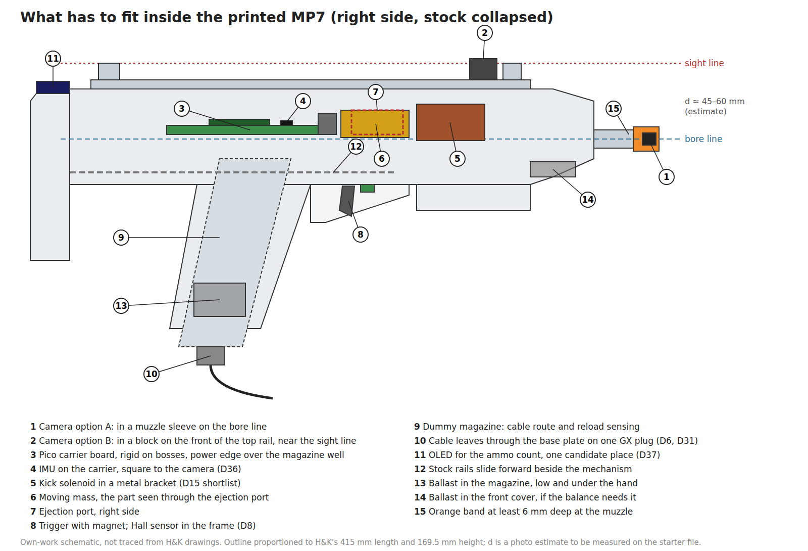
The order to place things in Fusion, because each constrains the next:
- The skeleton datums (Volume 4): bore line, sight line, rail top, magazine axis.
- The camera, because its position is fixed by aiming, not by space (5.2).
- The magazine and its cable path, because the grip leaves no choice about where it goes (5.6).
- The kick module, the biggest and heaviest thing inside, behind the ejection port (5.4).
- The carrier, into the space that remains, with its power edge over the magazine well (5.3).
- Trigger, controls, OLED, then the cable runs between them all (5.5, 5.7, 5.9).
5.2 The camera
5.2.1 Bore line or sight line
The camera has to look straight ahead from the front of the gun. Where at the front is a real trade, and the printed gun is where it gets decided, because a printed front cover can put the camera anywhere.
Aiming Maths and Calibration Vol 5 shows that a camera a distance d from the line the player aims along gives an aim error that calibration can remove at one playing distance only, and that over 0.6 to 1.6 times that distance the worst error is about 0.6 · d. With an error budget of about 5 mm on a 55-inch screen, d should be about 8 mm or less. Its proposal: “design parallax out by placing the camera within about 8 mm of the sight line in the MP7 shell”.
On an MP7 the sight line runs along the top of the top rail, through the iron sights or a reflex sight, well above the bore. Measured roughly off a side photograph scaled to H&K’s 415 mm length, the bore-to-iron-sight-line height d is somewhere around 45–60 mm. That is a photo estimate with a large perspective error; the starter file gives the real figure, and it is the first thing to measure in Fusion.
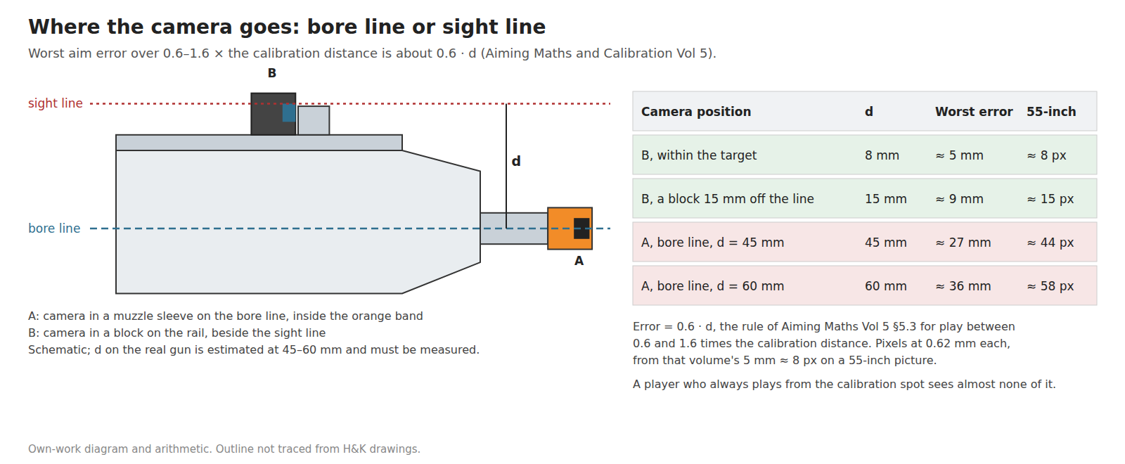
- Option A, the muzzle. The camera sits in a sleeve shaped like the flash hider, its lens at the muzzle face, inside the orange band. It is what the donor build planned (MP7 Donor Build Vol 2) and it is invisible. It costs aim: around 27–36 mm of worst-case error on a 55-inch screen if d is 45–60 mm. For a player who always plays from the spot where the gun was calibrated, the same volume notes, it hardly matters.
- Option B, near the sight line. The camera sits in a block on the front of the top rail, within about 8 mm of the sight line. On an MP7A1 the natural home is the front sight’s base: the real gun has a flip-up front sight there. The cost is realism: a front sight a little bulkier than H&K’s.
- Which sight line. Iron sights and a reflex sight give different sight lines, tens of millimetres apart. The camera can be near only one. If the gun will wear a dummy reflex sight, option B moves into or beside that sight instead.
Proposed: design the front cover and front sight to take the camera in both places, with the camera axis a user parameter (cam_offset_z, Volume 4), print both, and decide on the bench with the parallax test that Aiming Maths Vol 5 sets out (calibrate at the usual distance, then read the cursor offset at 1.5, 2.0, 3.0 and 3.5 m). Print is cheap; this is exactly the question a printed gun can answer and a donor cannot.
5.2.2 The aperture: why the kit camera must be flush
The MP7 Donor Build dive derived the rule for a lens set back behind an opening: the opening must be at least 2 L tan(FOV/2) across for a set-back L. The kit camera, the PixArt PAJ7025R3 (D18, Reference Electronics Vol 3), has a field of 113° horizontally and vertically by its datasheet as that dive records it. With FOV/2 = 56.5°, tan 56.5° ≈ 1.51, so the opening must be about three times the set-back: a lens 2 mm behind the face needs a 6 mm opening; 5 mm behind needs 15 mm. In practice the lens sits flush with, or proud of, the front face of its housing. The R3 stands on edge on a small breakout, lens looking along the board, located by two 0.8 mm posts (Reference Electronics Vol 3, §3.7), so the housing is a printed pocket that holds the breakout square to the camera axis and lets the lens reach the face.
5.2.3 Square, rigid, and the orange band
- Square to the bore (or to the chosen sight line). Reference Electronics Vol 3 sets the alignment rules: axis parallel to the line the firmware calibrates against, and no movement in the mount. A printed pocket with a datum face and a screw clamp does both.
- Rigid against the kick. The front cover takes the camera, and the kick module is behind it; the camera’s housing is screwed to the front cover through heat-set inserts, not glued.
- Orange band. Option A’s sleeve, printed in orange PETG, is the band if it covers the outside circumference for at least 6 mm from the muzzle (16 C.F.R. § 1272.3(b), MP7 Donor Build Vol 3). With option B the band is still needed at the muzzle, on a dummy sleeve with no camera in it. Whether a given orange filament is at least as bright as Fed-Std-595B 12199 is not stated by the filament makers; checking it against the airsoft donor’s orange flash hider, or a 12199 colour chip, is cheap.
Decided (19 October 2026, D43): both camera mounts are printed, mount A at the muzzle and mount B near the sight line, and the bench parallax test decides between them. The sight question is answered the same way: printed mock-ups of both a reflex sight and iron sights, tried on the gun.
5.3 The carrier board and the IMU
Where. The Reference Electronics Vol 8 floorplan puts the camera connectors at the muzzle end, the Pico in the middle and the power stages, their interlock, the power entry J12 and the bulk capacitor on the edge over the magazine well, because every cable leaves through the magazine. In the printed receiver that means: flat, high in the receiver above the magazine well, between the trigger group and the kick module, the same “receiver void first” the donor dive proposed (P-MP7-7).
How it is held. Four (or more) printed bosses with M3 heat-set inserts (Volume 6), the board screwed down on short standoffs. The Positional and Inertial dive sets two rules for the IMU that is now on the carrier (D36): rigid to the receiver, because “a flexing board turns the solenoid’s kick into a ringing the gyroscope reads as rotation”, and square to the camera, so the firmware needs no rotation between the two. Both are design rules for the shell: the bosses are thick and close to the IMU, and the boss faces are machined into the model parallel to the camera axis datum.
Which drives which. Reference Electronics Vol 8 §8.11 lists “Donor’s internal envelope” as the input that blocks the carrier’s outline. In a printed gun the dependency can run the other way: the outline can be chosen for the electronics and the shell drawn round it, within the MP7’s outside. The working proposal is to measure the free height and width at the carrier station in the hollowed starter (Volume 4), hand that envelope to the Altium layout as its maximum, and then fix the bosses to the board’s actual mounting holes. A question for the owner, since it touches both dives.
Pico height. The Pico is 21 × 51 mm on a 1 mm board; its height with the USB socket, and the carrier’s with sockets (P-RE12), are not in the datasheet text and need measuring before the receiver’s carrier zone is frozen (MP7 Donor Build Vol 2 §2.8).
Decided (19 October 2026, D44): the printed shell sets the carrier board’s maximum outline, and the shell carries the mounting slots or posts the board is drawn to. The Altium layout starts from the envelope this section gives.
5.4 The kick and the moving ejection port
The brief is kick plus a moving ejection port (plan decision 4), and D5 says try both ways of doing the port: one solenoid for kick and port (concept A), or a separate port actuator (concept B). The MP7 Donor Build Vol 2 §2.6 sets out both. In a donor, concept A is constrained by the donor’s carrier; in a printed gun everything is chosen: the moving mass, its stroke, its guides, and the window it shows through.
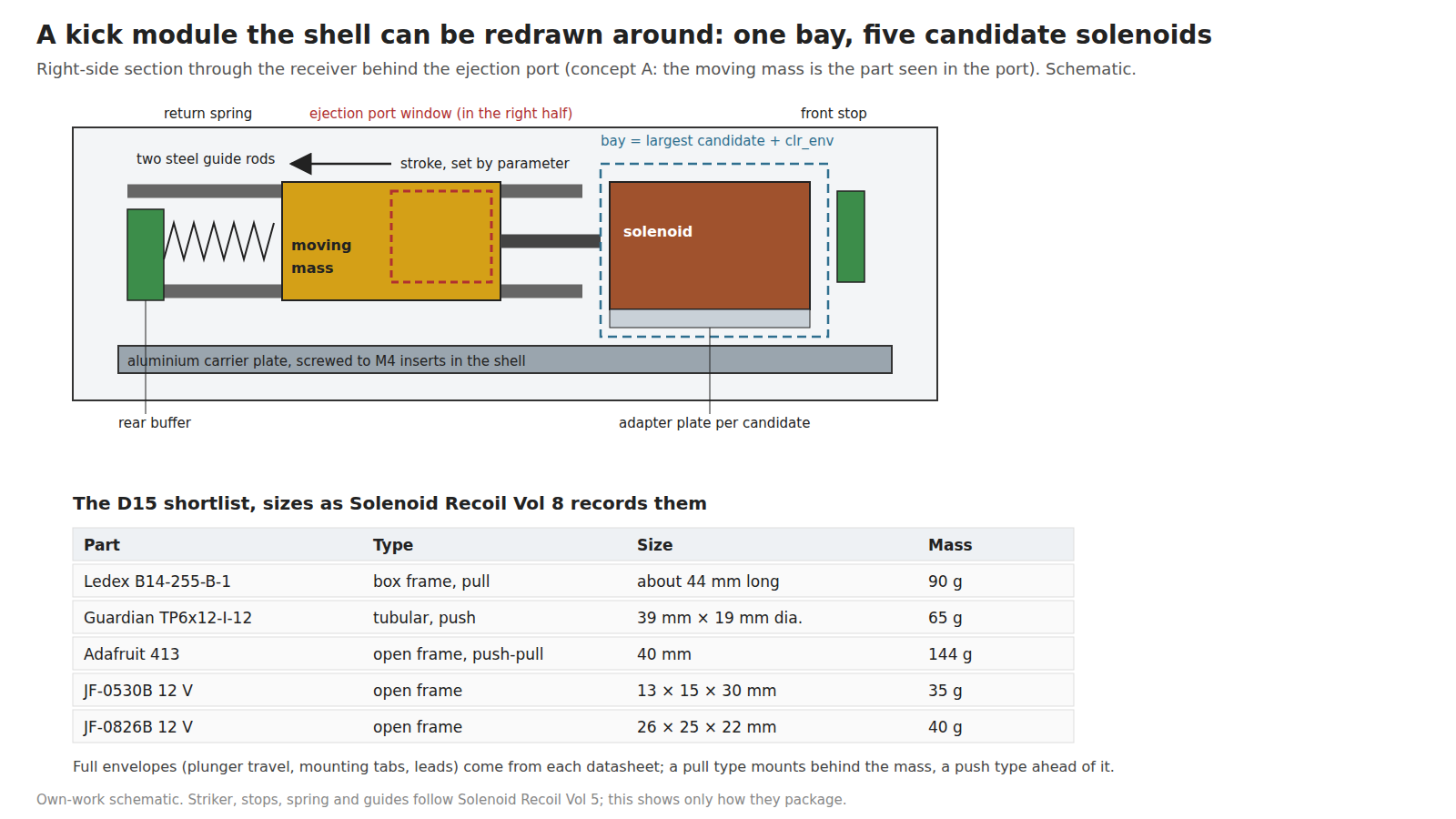
A module, not features of the shell. The proposal is a self-contained kick module on a flat aluminium carrier plate, cut on the lab’s Nomad 3 or Shapeoko, which carries the guide rods, the buffer, the front stop and the solenoid, and is screwed into the receiver through M4 heat-set inserts. The reasons:
- The impacts go into metal. Every shot slams the mass into the rear buffer. A printed boss taking that load directly will creep and its insert will loosen; a plate spreads it over several inserts and a large area of shell.
- The bench can rank solenoids without reprinting the gun. Each D15 candidate gets its own small adapter plate on the module, and the bay is sized for the largest of them plus
clr_env. The Solenoid Recoil Vol 6 rig and the gun use the same module. - Heat goes into metal. Coil heat (Solenoid Recoil Vol 7) sinks into the aluminium plate instead of softening PETG.
The moving mass is the part seen through the port (concept A), so its right side is finished to look like the real gun’s bolt carrier through the window, and its mass and stroke are what the kick is made of. The design of the striker, the stops, the spring, the guides, and where in a long gun the kick should be placed, belongs to Solenoid Recoil Vol 5, which this module follows: brass for the mass (SR-7), steel rods, a damped rear stop. The real MP7’s bolt moves at 6–8 m/s (HK MP7 Vol 5); the light gun’s mass will not, and does not need to.
Concept B needs room for a second, small actuator beside the port. The module plate leaves space ahead of the moving mass for one; the port part it moves, and the actuator choice, are the Moving Ejection Port dive’s. The two stages never fire at the same instant (D16); that is firmware and the carrier’s interlock (P-RE21), not the shell.
The port window. The real MP7’s ejection port is on the right, with a case deflector behind it (HK MP7 Vol 5). The printed right receiver half has the window; the moving mass fills it.
5.5 The trigger and the other controls
Trigger. D8 makes the trigger a Hall-effect input: a magnet in the trigger, a sensor in the frame (Reference Electronics Vol 4). The proposed magnet is a 5 × 2 mm N52 axial disc (P-RE6), to be re-picked from the measured travel. For the shell that means: a printed trigger on a steel pivot pin through both receiver halves; a pocket in the trigger for the magnet, glued; a small sensor board screwed to a boss in the frame facing it, at a gap set by the travel; a return spring and a hard over-travel stop. Pull weight, travel, wall and reset, and the trigger’s feel, belong to Controls and Inputs (being written), which this mounting follows. The real MP7’s pull is 30–45 N (HK MP7 Vol 5), heavy for a game.
Other controls. The real gun has a selector, a magazine catch, a bolt catch, a charging handle, a stock release and a foregrip release, ambidextrous where it matters (HK MP7 Vol 5). Which of them become inputs (a selector that sets single or automatic fire, a charging handle that “reloads”) is Controls and Inputs’ decision. Two facts from other dives bound it: OpenFIRE’s button map on the Pico is full (26 of 26 GPIO with the kit camera, P-RE19), so any extra input costs a pin or a multiplexer; and each real control that becomes an input needs a switch envelope and a boss in the shell. Design every real control as a moving part with space for a switch behind it, and let Controls and Inputs say which switches are fitted.
5.6 The magazine
D6 put the cable out through the magazine base plate “for now” and said “revisit for the printed build”. D31 then made it one GX connector at the base plate. Revisited: keep both. In a printed gun the magazine is designed rather than sacrificed, so the arguments against it in a donor (machining a spare gas magazine, D21) fall away, and the arguments for it stay: the grip and stock remain untouched, the cable leaves where a hand never is, and the magazine is a natural strain-relief housing.
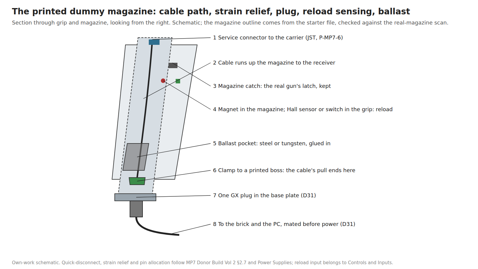
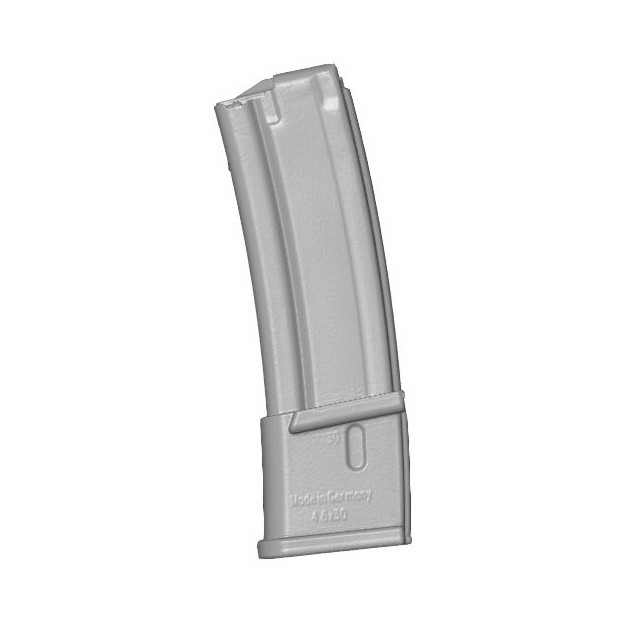
- Outline. The outside comes from the starter file and is checked against the swi-sro scan of a real 30-round magazine (Volume 2), the one piece of geometry measured from a real H&K part. H&K gives empty magazines as about 100, 150 and 200 g for 20, 30 and 40 rounds (HK MP7 Vol 5).
- Plug. One GX connector in the base plate carrying USB and the 24 V rail (D31). The base plate’s width decides GX12 or GX16, and panel or inline mounting (P-MP7-5); the GX16’s current rating is still to be confirmed from a maker’s datasheet (Power Supplies). It is mated before the brick is plugged in, and pins are allocated so a one-position slip cannot put 24 V on a USB or logic pin (D31).
- Strain relief. The cable is clamped to a printed boss inside the magazine so that no pull reaches the plug’s solder cups, the magazine catch or the carrier (P-MP7-6). A latched service connector at the top lets the magazine come out on its cable for service.
- Reload sensing. A magnet in the magazine and a Hall sensor or switch in the grip tell the firmware the magazine is seated; pulling it and re-seating it is a reload. The input itself is Controls and Inputs’.
- Ballast. The magazine sits under the hand and low in the gun, the best place for weight (Volume 7).
5.7 The OLED
D37 keeps the OLED, on the shared I2C1 bus with the IMU (PI-2), for an ammo count later. A real MP7 has no display, so wherever it goes it is a visible departure from realism. The candidates:
Table 1 — D37 keeps the OLED, on the shared I2C1 bus with the IMU (PI-2), for an ammo count later. A real MP7 has no display, so wherever it goes it is a visible departure from realism. The candidates
| Place | Visible when | Realism cost | Note |
|---|---|---|---|
| Top of the backplate, under the rear sight, facing the shooter | Aiming, at the edge of view; at a glance down | Low: small, behind the sights, invisible from the side | Proposed first |
| Left side of the receiver above the grip | Held at the ready, not when aiming | Medium: a window in a large plain face | Easy to wire; where many light guns put one |
| Inside a dummy reflex sight on the rail | Always, in the sight picture | Low if the sight is fitted anyway | Conflicts with camera option B’s sight line; the screen is the sight |
| In the magazine base plate | Never, in use | None | Pointless for an ammo count |
The choice is the owner’s. The shell carries a parametric pocket for the module’s outline at the chosen place; the module’s dimensions come from the part that is bought.
Decided (19 October 2026, D45): the OLED goes on top of the backplate under the rear sight, as proposed, for now.
5.8 Stock, foregrip and rails
Stock. The real stock is a pair of rails ending in a butt plate that slide into the receiver alongside the bolt’s path and lock in each position, released by a lever at the rear right (HK MP7 Vol 5). Printed rails would flex and wear; the proposal is steel or aluminium rails (rod or flat bar cut in the lab, matching the starter’s section) sliding in printed channels with clr_slide, a spring plunger or ball detent clicking into notches for each position, and a printed release lever. The rails run beside the kick module, so the channels and the module are drawn together.
Foregrip. It folds back under the fore-end and locks firmly open, lightly closed (HK MP7 Vol 5). A steel pin for the pivot and a ball detent at each end of travel give both.
Rails. The real gun’s top rail is metal, MIL-STD-1913, carrying the sights and optics; the side rails screw to threaded bushes at 3 and 9 o’clock (HK MP7 Vol 7). Printed rails crack under an optic’s clamp. The proposal is bought aluminium Picatinny rail sections, cut to length and screwed into heat-set inserts. A metal top rail also covers a top seam, if the split chosen in Volume 6 puts one there.
5.9 Cable runs inside the gun
Reference Electronics Vol 8 sets the electrical rules: the solenoid leads twisted and never alongside the camera lead; high-current wiring as short as possible, over the magazine well; the camera bus away from the pulse loops. For the shell:
- A camera channel along one side or under the top rail, from the front cover to the carrier’s camera connector, opposite the side the solenoid leads use.
- Printed clips every 40–60 mm, so no lead touches the moving mass or the stock rails.
- The solenoid leads run straight down from the kick module to the carrier’s power edge, twisted.
- Nothing crosses a split line loose: where a lead must cross from one part to another, it does so at a connector or through a grommeted slot.
5.10 Why this, and why not the others
Table 2 — 5.10 Why this, and why not the others
| Choice | Pick | Status | Why, and why not the others |
|---|---|---|---|
| Camera position | Both A (muzzle) and B (sight line) printed; decide on the bench | Proposed | A is realistic and costs ~27–36 mm worst-case aim error if d is 45–60 mm; B meets the 8 mm target at a small realism cost; firmware parallax correction is not recommended as it stands (Aiming Maths Vol 5) |
| Kick module mounting | Aluminium plate on M4 inserts, solenoid on per-candidate adapter plates | Proposed | Puts impact and heat into metal; lets the D15 bench ranking change the solenoid without reprinting. Rejected: solenoid screwed to printed bosses (creep, heat), solenoid glued (no swap) |
| Carrier position | Flat, high in the receiver above the magazine well, on M3 inserts | Proposed | Shortest power leads to the exit (Reference Electronics Vol 8); rigid for the IMU. Rejected: in the magazine (room for the plug and ballast instead), split board (not the reference carrier) |
| Cable exit | Keep D6/D31: one GX at the magazine base plate | Proposed (revisits D6) | In a printed gun the magazine is designed, not sacrificed; grip and stock untouched. Rejected: through the stock (moving), through the grip back (realism, hand) |
| OLED | Top of the backplate under the rear sight | Proposed; owner’s choice | Visible when aiming, invisible from the side. Alternatives in 5.7 |
| Stock rails | Metal rod or bar in printed channels, ball detent | Proposed | Printed rails flex and wear |
| Top and side rails | Bought aluminium Picatinny sections on inserts | Proposed | Printed rails crack under clamps; metal is what the real gun has |
5.11 What could not be verified
- The real bore-to-sight-line height (photo estimate 45–60 mm); it comes from the starter file.
- Whether any orange filament meets AMS STD 595A-17 colour 12199 (the old Fed-Std-595B 12199) or brighter.
- Pico and carrier heights with sockets and connectors.
- GX16 current rating from a maker’s datasheet; base-plate width (GX12 versus GX16).
- The OLED module’s outline, until one is bought.
Sources
- Aiming Maths and Calibration Vol 5, §§5.3, 5.9, 5.10 (0.6 · d, the 8 mm proposal, the bench test).
- Reference Electronics, Vol 3 §3.7 (camera mounting, PAJ7025R3 breakout), Vol 4 (Hall trigger, P-RE6), Vol 8 §§8.3, 8.7, 8.11 (floorplan, cable exit, what blocks the outline).
- Positional and Inertial Vol 6, §6.6 (IMU placement).
- Solenoid Recoil, Vol 5 (moving mass, stops, guides), Vol 7 (heat), Vol 8 (the D15 shortlist and its sizes).
- MP7 Donor Build, Vol 2 §§2.5–2.8 (camera aperture rule, port concepts, base-plate exit, carrier placement), Vol 3 (marking).
- HK MP7, Vol 5 (assemblies, magazine weights, stock, foregrip, controls, trigger pull, bolt velocity) and Vol 7 (rails).
- Owner decisions D5, D6, D8, D13–D16, D18, D21, D31, D36, D37; part rows P-MP7-5, P-MP7-6, P-MP7-7, P-RE6, P-RE12, P-RE19, P-RE21, PI-2, SR-7 (
Light-Guns/DECISIONS.md).
Comments (0)