MP7 Light Gun: Printed Build · Volume 6
Splitting, Joining and Printing the Shell
Getting a 415 mm gun off a 250 × 210 mm bed: where to cut the shell and why, keys, dowels, screws and heat-set inserts sized from the maker's table, walls and infill that survive a solenoid, a material for each part with the reasons, orientation and supports, test coupons before parts, and the post-processing that turns prints into an assembly
6.1 The printers and the problem
The lab’s catalogued printers are two heavily modified Prusa MK3S+ (_shared/lab_capability.md; the owner says there are “many 3D printers”, the rest not yet catalogued). Prusa’s product page gives the MK3S+ build volume as 250 × 210 × 220 mm (read 19 October 2026; the brief quoted 210 mm high, the family’s often-quoted figure). The modifications may have changed it; the real usable volume of each printer is the first measurement to make.
The MP7 is 415 mm long with the stock in, by H&K’s 2011 data. The bed’s diagonal is 326 mm. Nothing that long fits on the bed at any angle, so the gun is printed in pieces, and the receiver itself (roughly 315 mm long and 170 mm tall including the grip, estimated from a scaled side photograph) does not fit either.
The printers, confirmed (19 October 2026, D46): both MK3S+ machines have Prusa’s standard build volume (250 × 210 × 210 mm, 220 mm height on Prusa’s current page), so the split below stands. One of the two is enclosed, which puts ASA within reach for parts that want its heat resistance and outdoor stability (§6.5); PETG remains the default.
6.2 Where to cut
Three kinds of cut, in order of preference:
- The real gun’s own part lines. The real MP7 comes apart into a receiver, a backplate with the stock and charging handle, a front cover, the bolt group and the magazine (HK MP7 Vol 5). Seams there look right because they are there on the real gun. The starter file already models these as separate bodies (Volume 2).
- A plane of symmetry. Cutting the receiver on its vertical mid-plane (a clamshell) is how almost every light-gun shell is made, and for good reason: each half prints lying on its flat split face, its outside up and clean, and the inside is open for fitting the electronics. The cost is a seam along the top and round the grip that the real gun does not have.
- A transverse cut, where nothing else will make a piece fit the bed.
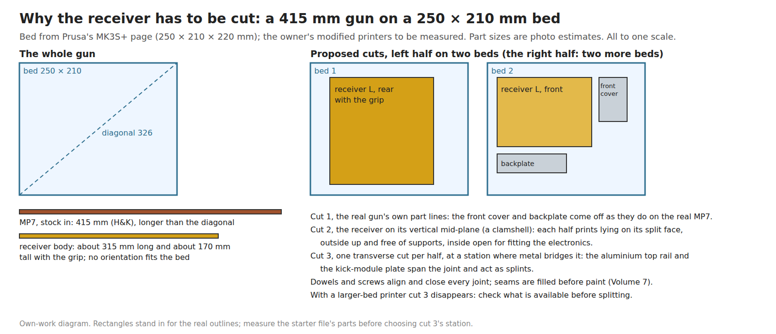
The options for the receiver, compared:
Table 1 — The options for the receiver, compared
| Option | Pieces | For | Against |
|---|---|---|---|
| Clamshell plus one transverse cut per half | 4 receiver pieces + front cover + backplate | Every piece lies flat with its outside up; inside fully open; the transverse joint can sit where the metal top rail and the kick-module plate bridge it | Seams on top, round the grip and across each side, all to fill |
| Upper and lower (horizontal cut under the top rail) | Lower with grip, upper cover; each still too long, so a transverse cut too | The top rail hides the main seam; the lower is one piece round the grip | The upper is long and thin, prints standing or diagonal; the lower’s inside is a deep pocket, harder to fit and support |
| Many small pieces at every natural feature | 8–12 | Each piece small and easy | More joints, more alignment error, more filling; weaker |
| One piece on a larger printer | 1–2 | Fewest seams | Needs a printer that may not be in the lab |
Proposed: the clamshell with one transverse cut per half, placed at a station where metal bridges it: the bought aluminium top rail across the top (Volume 5), and the kick module’s aluminium plate inside. Bridged that way, the transverse joint carries almost no bending, and its seam is the only one that has to be invisible on a side face. The exact station waits on the starter file’s measured part lengths; place it with the bed boxes in the skeleton (Volume 4) and keep it clear of the ejection port, the trigger pivot and the selector.
6.3 Joints: keys, dowels, screws and inserts
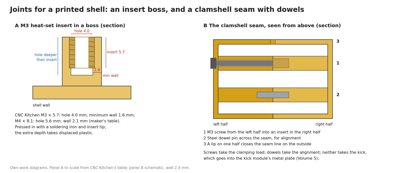
Heat-set inserts turn printed holes into metal threads that survive repeated assembly. CNC Kitchen’s table, as its retailer 3DJake reproduces it (read 19 October 2026), gives for each size the insert’s diameter, the hole diameter and the minimum wall thickness round it:
Table 2 — Heat-set inserts turn printed holes into metal threads that survive repeated assembly. CNC Kitchen's table, as its retailer 3DJake reproduces it (read 19 October 2026), gives for each size the insert's diameter, the hole diameter and the minimum wall thickness round it
| Insert | Length | Insert ⌀ | Hole ⌀ | Min. wall |
|---|---|---|---|---|
| M3 standard | 5.7 mm | 4.6 mm | 4.0 mm | 1.6 mm |
| M3 short | 3.0 mm | 4.6 mm | 4.0 mm | 1.6 mm |
| M4 standard | 8.1 mm | 6.3 mm | 5.6 mm | 2.1 mm |
| M4 short | 4.0 mm | 6.3 mm | 5.6 mm | 2.1 mm |
| M5 standard | 9.5 mm | 7.1 mm | 6.4 mm | 2.6 mm |
CNC Kitchen’s US store listed the M3 × 5.7 at $10.90 per 100 and the M4 × 8.1 at $11.50 per 50 on 19 October 2026. ruthex’s M3 × 5.7 has the same figures. Those numbers go straight into the user parameters (hole_m3_insert, wall_boss, Volume 4) and the coupon in 6.7 confirms them on the owner’s printers. The hole is made deeper than the insert so that displaced plastic has somewhere to go, and the insert is pressed in square with a soldering iron and an insert tip.
Where each size goes. M3 for the clamshell screws, the carrier bosses, the camera housing and the rails; M4 for the kick-module plate, which takes the impacts.
Screws. M3 socket-head screws from the left half into inserts in the right, so the right side (with the ejection port) stays clean; where a screw head shows on the outside, a domed or pin-style head that resembles the real gun’s pins and screws. Clearance holes in the screw-side half: 3.4 mm, the ISO medium clearance for M3, adjusted by the coupon.
Alignment. Screws clamp; they do not locate. Steel dowel pins (3 mm, in a press-fit hole on one side and a close sliding fit on the other, both set by coupon) align each clamshell joint and each transverse joint. A lip a few tenths of a millimetre proud on one half, sitting in a matching rebate on the other, closes the outside seam line and hides small mismatch.
Glue or screws. Joints that must open (the clamshell, the magazine, the front cover) are screwed. Joints that never open (the transverse cut, once fitted) can be bonded as well as dowelled, with epoxy or a cyanoacrylate suited to the material, after the electronics are known to fit.
6.4 Walls, infill and the kick
In a fused-filament print, strength comes mostly from the perimeters (the solid outer walls) and the top and bottom skins; infill holds the walls apart and carries little. For a shell that is held, knocked and kicked:
- Walls of six perimeters (2.4 mm with a 0.4 mm nozzle, the
wallparameter) on the shell, more round every boss and insert, so each insert sits in solid plastic as the maker’s minimum-wall figure assumes. - Infill 25–40 %, gyroid or another 3D pattern, where a region is solid in the model. A community print profile for a printed MP7 foregrip on Printables asks for “4+ walls, 30%+ infill”, which is in the same range. These are starting points, not tested figures.
- The kick does not go into plastic. Every impact of the moving mass ends in the kick module’s aluminium plate, which spreads it across several M4 inserts and a large area of shell (Volume 5). Without that, a boss taking a solenoid impact hundreds of times a session will creep and loosen its insert.
- Thicker where the hand pushes: the grip, the magazine well’s lips and the stock’s channels.
6.5 A material for each part
Table 3 — 6.5 A material for each part
| Part | Material | Why | Why not the alternatives |
|---|---|---|---|
| Shell, magazine, foregrip, controls | PETG (Prusament PETG, $29.99/kg, 19 October 2026) | Tough rather than brittle; softens at a higher temperature than PLA, so a coil-warmed or sun-warmed gun keeps its shape; Prusa lists it for the MK3S+ without an enclosure; sands and paints | PLA: stiffer and easier, but more brittle and softer when warm. ASA and ABS: Prusa lists them for the MK3S+ only “when using the Original Prusa Enclosure with filtration add-on”; PA: the same, plus drying |
| Fit coupons, first trial prints | PLA | Fast, cheap, accurate; it does not matter that a coupon is brittle | — |
| Small stiff brackets (camera housing, trigger) | PETG carbon fibre (Prusament PETG CF, $54.99/kg) or plain PETG | Stiffer, dimensionally steadier | Abrasive filaments wear a brass nozzle; a hardened nozzle is needed. Plain PETG first; CF only if a bracket flexes |
| Butt pad, buffer pads | TPU | Soft, grips, damps | — |
| Muzzle band | Orange PETG (Prusament PETG Prusa Orange was listed at $29.99) | The band can be the part itself (Volume 5, 5.2) | Paint can chip off; the brightness against AMS STD 595A-17 colour 12199 is unverified |
| Kick module plate, stock rails, top rail | Aluminium and steel, not printed | Impacts, wear and clamping loads (Volume 5) | — |
If the lab has an enclosed printer among the uncatalogued ones, ASA becomes a candidate for the outer shell: it weathers better than PETG and finishes well. That is a question for the owner, not a change to the plan.
6.6 Orientation and supports
- Clamshell halves lie on their split face, outside up. The cosmetic outside then has no support marks, the large flat split face is the first layer, and the layers run along the gun’s length, which is the direction a dropped or knocked gun bends.
- Bosses perpendicular to the bed come out round and true and take inserts well.
- Supports only inside, where they will not be seen: under the magazine well’s overhangs, the trigger guard’s inside, the port window’s top edge. PrusaSlicer’s organic supports reach those spots with small contact areas.
- Small round parts (the camera sleeve, the muzzle band, the dummy barrel) stand on end so their outside is a clean cylinder.
- The magazine prints in two halves lying flat, like the receiver, so its cable channel and strain-relief boss are open to fit, then closes with screws.
6.7 Test coupons before parts
A coupon costs minutes and a few grams; a failed receiver half costs most of a day and 100 g or more. Print these first, on the printer and in the filament that will make the parts, and put the results in the user parameters:
Table 4 — A coupon costs minutes and a few grams; a failed receiver half costs most of a day and 100 g or more. Print these first, on the printer and in the filament that will make the parts, and put the results in the user parameters
| Coupon | What it settles | Parameter |
|---|---|---|
| Peg and hole set at 0.05–0.10 mm steps | Sliding fit and locating fit per side | clr_slide, clr_fixed |
| Insert holes at 3.8, 3.9, 4.0, 4.1, 4.2 mm (M3) | The hole that grips and does not split; a Printables “Threaded Insert Hole Tolerance Test” (model 1040630) exists, built around CNC Kitchen’s recommendations | hole_m3_insert |
| Dowel holes, press and slide | The pin fits in 6.3 | — |
| A 40 mm slice of the receiver at the transverse cut | Lip, dowels and seam together | the joint geometry |
| A section of the stock channel with a rod in it | The slide and the detent click | clr_slide |
| A Picatinny rail section screwed to a printed boss | Insert pull-out and the rail’s seating | — |
| An orange muzzle band | Colour against the airsoft donor’s orange or a 12199 chip | — |
6.8 Post-processing and assembly
- Remove supports, then dress the split faces flat on a sheet of abrasive on glass so the halves meet without a gap.
- Set the inserts with the iron, square to the boss, before any other fitting.
- Ream the dowel holes to the coupon’s size; press the pins into one half only.
- Dry-assemble the shell empty, check every joint, the stock’s slide and the foregrip’s click.
- Fit the electronics and the kick module, wire them (Volume 5), and run the Reference Electronics bring-up with the shell still open.
- Close and bond only what never opens; leave the clamshell screwed.
- Finish (Volume 7).
6.9 Why this, and why not the others
Table 5 — 6.9 Why this, and why not the others
| Choice | Pick | Status | Why, and why not |
|---|---|---|---|
| Receiver split | Clamshell plus one transverse cut per half, bridged by metal | Proposed | Flat printing, clean outsides, open inside; the alternatives in 6.2 cost more joints or a printer not catalogued |
| Fasteners | M3/M4 heat-set inserts, socket screws from the left | Proposed | Repeated assembly without stripping printed threads; CNC Kitchen’s sizes; screws on the left keep the port side clean. Rejected: screws into plastic (strip), nuts in traps (bulk, loosen) |
| Alignment | Steel dowel pins plus a seam lip | Proposed | Screws do not locate; printed pins shear |
| Shell material | PETG | Proposed | Toughness and heat on an open MK3S+. Rejected for now: ASA/ABS/PA (enclosure per Prusa), PLA (brittle, softer warm) |
| Insert hole | 4.0 mm M3 / 5.6 mm M4, coupon-confirmed | Proposed | The maker’s table; the coupon catches the printer’s own error |
6.10 What could not be verified
- Every part length here: they are photo estimates until the starter file is measured.
- The owner’s printers’ real build volume after modification, and whether a larger printer exists.
- CNC Kitchen’s table read from a retailer’s copy; CNC Kitchen’s own store page shows the price but not the table text.
- Whether any orange filament meets AMS STD 595A-17 colour 12199.
- Every print setting here is a starting point, not a tested figure.
Sources
- Prusa Research, Original Prusa MK3S+ product page, build volume and materials, read 19 October 2026, https://www.prusa3d.com/product/original-prusa-i3-mk3s-3d-printer-3/; Prusament PETG and ASA category pages, prices read 19 October 2026.
- CNC Kitchen threaded-insert comparison table, as reproduced by 3DJake, https://www.3djake.com/cnc-kitchen/threaded-inserts-m3-standard, read 19 October 2026; CNC Kitchen US store, product data, read 19 October 2026, https://cnckitchenus.store/.
- Printables, “Threaded Insert Hole Tolerance Test” (model 1040630) and an MP7 foregrip print profile (model 145240), as found by search, 19 October 2026.
- HK MP7 Vol 5, the main assemblies.
_shared/lab_capability.md, the lab’s printers and machines.
Comments (0)