MP7 Light Gun: Machined Aluminum · Volume 7
Living Inside a Metal Shell — Electrics, Radio, Heat, Weight, Cost and Time
What a conductive aluminium receiver does to electronics designed for a plastic one: grounding and static, keeping 24 V off the shell, a radio that needs a plastic window, the shorted-turn effect a closed aluminium loop has on the solenoid, heat in the hand, the weight and balance against the kick, what the metal gun costs at dated prices and how many machine hours it takes, and the checks before the first game
7.1 A plastic gun’s electronics in a metal box
Every electronics dive in the category was written for a gun with a plastic body: the airsoft donor, then the printed shell. Some of their decisions say so outright. The fully wired gun folds the USB cable’s shield back and insulates it at the GX plug, partly because “the GX has no spare pin, the printed gun has no chassis, and a shield bonded at the gun would be a second, parallel ground path between gun and PC” (Fully Wired Vol 5, row WD-4). The wireless dive’s antenna rule is “do not cover it with metal”, and it notes that “a printed MP7 shell is plastic, so the shell itself is not the problem” (Fully Wireless Vol 5 §5.7).
An aluminium receiver is a chassis, a shield and a conductor in the player’s hands. This volume takes each consequence in turn and proposes the smallest change that deals with it. None of it touches the carrier’s design (Reference Electronics); it concerns how the carrier and its wiring sit in the shell.
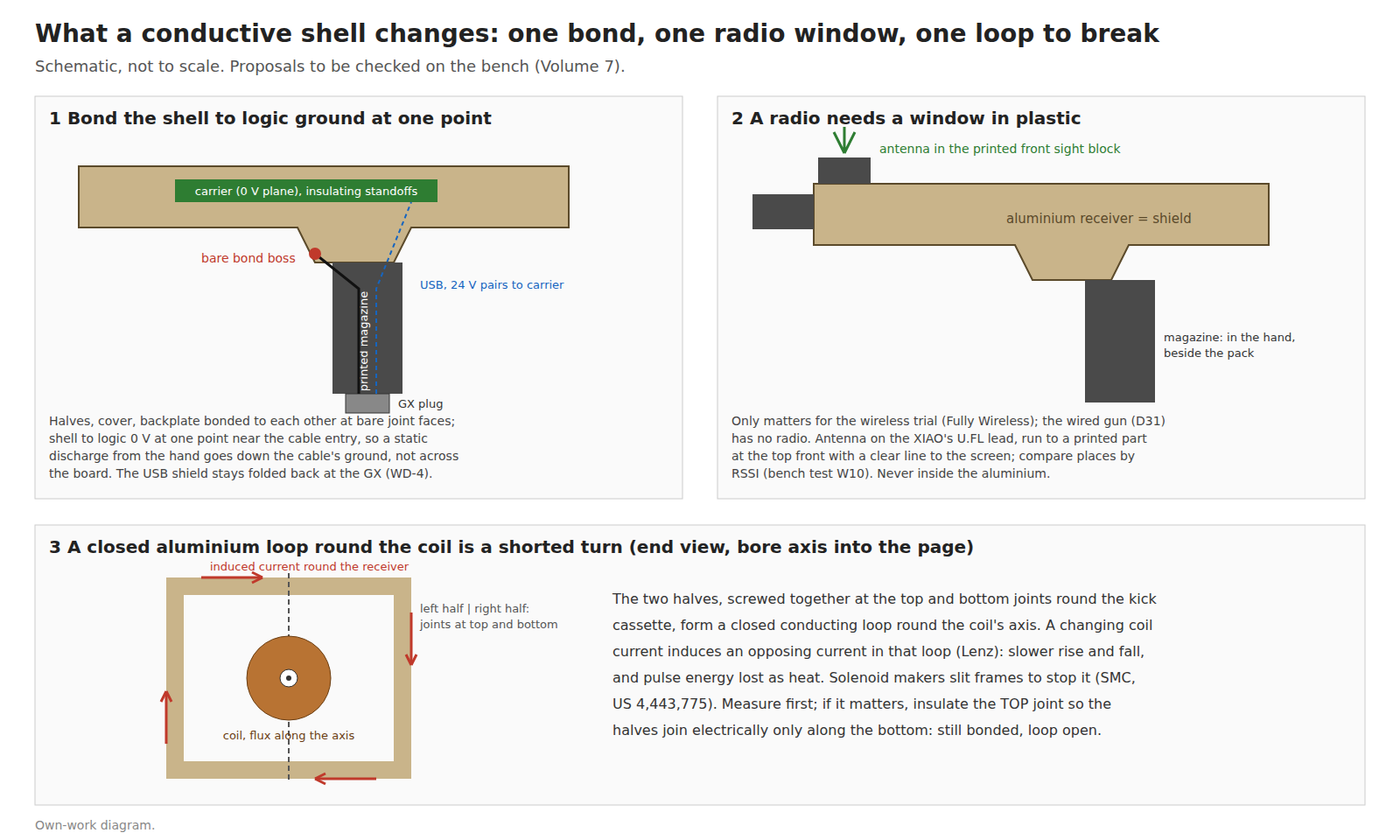
7.2 Grounding and static
The problem. A floating metal shell charges with static from the player’s hands and clothing and, when it discharges, it does so through the nearest path: an arc through a pinhole in the anodise or Cerakote to a screw, a standoff, a cable, the carrier. That is exactly how a light gun resets or drops off USB in the middle of a game in a dry winter room.
The proposal (MA-11).
- Bond the shell’s parts to each other. The receiver halves, front cover and backplate meet at joint faces masked bare (Volume 6 §6.7), with steel dowels and screws through them. A DMM across any two parts should read well under an ohm.
- Bond the shell to the carrier’s logic ground at one point, near the cable entry. A bare boss inside the grip core, close to where the cable comes up from the magazine’s GX plug, carries a ring lug on a short, heavy lead to the carrier’s ground at its connector. A static discharge into the shell then flows straight to the cable’s ground conductor and away to the PC, whose 0 V is tied to mains earth (Fully Wired Vol 5), without crossing the carrier’s ground plane. Bond to the logic and USB ground, not to the 24 V return, so pulse current never has a reason to use the shell.
- Everywhere else, keep the carrier insulated from the shell: insulating standoffs (Volume 5 §5.10), a thin PET or polyimide sheet under the board where it sits close to the deck. One bond, not many: a second contact would let ground current divide between the shell and the board.
- The USB shield stays as WD-4 has it, folded back and insulated at the GX. WD-4’s reason, avoiding “a second, parallel ground path between gun and PC”, still holds: the shell is bonded to the USB ground conductor, not to the shield, so there is still one path.
For the wireless gun the shell bonds to the pack’s 0 V the same way; with no cable there is nowhere for a discharge to go, and the large bonded shell simply rises and falls with the circuit, which is benign.
Checking it. The lab’s catalogue lists no ESD simulator (question 8). A pragmatic test: with the gun running a game, walk across a carpet in a dry room and touch the shell, many times, watching for resets, USB drop-outs or cursor jumps, then the same with the bond lead removed. A proper IEC 61000-4-2 gun is the real instrument if one can be borrowed.
7.3 Keeping 24 V off the shell
The 24 V rail (D14) and the solenoid’s pulse current now run inside a conductor that is bonded to ground. A lead chafed through against a sharp aluminium edge is a short across the brick, which the brick’s protection and the carrier’s input stage should survive, but it is a fault to design out:
- Grommets in every hole a lead passes through (cable holes off the bore axis, Volume 2 rule 6), and every edge a lead crosses broken to a radius.
- Leads clipped clear of the moving mass and the stock rails, as the printed build already requires (Printed Build Vol 5 §5.9).
- The solenoid’s own frame, if it has terminals or a metal frame near the live end, mounted on the cassette’s insulating stops or adapter plate, not straight on bare aluminium.
- A DMM check before first power: no continuity between any GX pin except ground and the shell.
7.4 The radio
The default gun is wired (D31); it has no radio and nothing here applies. The wireless trial (D30) and the kit route (WL-2) put a 2.4 GHz radio in the gun, and an aluminium receiver is, to that radio, a nearly closed metal box.
- The antenna goes in a plastic part. The printed parts that stay printed (Volume 3) are the candidates: the front sight block at the top front (clear line to the screen and dongle, away from the hand), the camera housing in the orange sleeve (next to the camera’s cable), the magazine (inside the hand and beside the pack, the drawbacks Fully Wireless already lists) and the grip panels (under the palm).
- A remote antenna makes this practical. Fully Wireless notes that among its boards only route B’s Seeed XIAO nRF54L15 has a U.FL antenna socket; with it the radio can sit on or near the carrier inside the metal while a small antenna on a short lead sits in the front sight block. That is a further reason for WL-2’s route B in a metal gun.
- Do not rely on gaps. The seams between halves and around the backplate leak RF, but unpredictably, and a hand closes them.
- Measure. Fully Wireless’s bench test W10 logs RSSI at the dongle for each antenna place; run it in the metal shell, gun held normally.
7.5 The camera, the IMU and the Hall trigger
- Camera. Aluminium does nothing to the camera’s optics. The camera stays in its printed housing in the orange sleeve or the front sight block, with the lens flush at the face (Printed Build Vol 5 §5.2); with the lens at the face and the PAJ7025R3’s field of about 113° (Reference Electronics Vol 3), the gun’s body lies behind the lens plane and is never in view. A matt black finish round the aperture avoids stray reflections. What metal improves is the mount: a printed housing bolted to a machined datum face stays square to the bore.
- IMU. The LSM6DSOX (D38) has no magnetometer, so a metal shell does not disturb it; the stiffer receiver helps it, as Volume 1 argued.
- Hall trigger. Aluminium is non-magnetic and leaves the trigger magnet’s field alone; keep steel screws and pins out of its neighbourhood (Volume 5 §5.10).
7.6 The solenoid and a shorted turn
This effect has no counterpart in the printed gun and is not covered elsewhere in the category.
A solenoid’s current rises and falls in milliseconds on every shot (Solenoid Recoil). Any closed conducting loop that encircles the coil’s axis links some of that changing flux, and by Lenz’s law a current is induced in the loop that opposes the change. The loop behaves as a shorted secondary winding: it slows the rise and fall of the field and turns part of each pulse’s energy into heat in the loop. Solenoid makers design against it: SMC’s US patent 4,443,775 (1984) puts slits in the magnetic frame’s plates “for elimination of eddy current loss”, which it says “permit effective utilization of available electrical power”.
In the machined gun the kick cassette sits on the bore axis with the solenoid’s axis along it, and the two receiver halves, screwed together at the top and bottom of the receiver round the cassette, form exactly such a loop (panel 3 of the figure). So may an all-aluminium cassette frame if it closes round the coil (Volume 3 put the frame in 6061). How much this costs the kick is unknown: much of an unframed solenoid’s return flux closes inside a loop as large as the receiver’s section, which reduces the net flux linked, and D13’s regulated current stage may hide part of the slower rise. It may be negligible; it should be measured, not assumed.
The proposal (MA-12).
- Draw the cassette frame open, a U or a frame with a slit through one side, so it is never a closed ring round the coil; costs nothing.
- Measure in the receiver. On the Solenoid Recoil bench rig (Vol 6, which already uses “a block of aluminium or steel of about 1 to 2 kg” as its test mass), record the coil current’s rise and the kick with the cassette in the printed gun and then in the assembled metal receiver, same supply, same pulse, ADP3450 on the shunt.
- If the difference matters, open the receiver’s loop: leave the anodise or Cerakote on the top joint face, and put nylon shoulder washers on the screws through the top of the cross ribs, so the halves meet electrically only along the bottom joint. They stay bonded for Section 7.2, and the loop round the coil is broken.
7.7 Heat
Solenoid heating is owned by Solenoid Recoil Vol 7, including its advice on “metal or high-temperature mounting” and a firmware-read temperature sensor for a coil that sees automatic fire. A metal receiver changes two things:
- The coil sinks into the whole gun. The cassette bolts to aluminium with a thermal conductivity of 167 W/m·K (Protolabs, 6061), so the coil runs cooler than on a printed plate, and the heat spreads.
- The player holds the heat sink. In a long automatic-fire game the receiver warms where the hand and cheek are. Measure the shell’s temperature next to the cassette and at the grip after the worst game in the library, with a thermocouple on a DMM, and keep the firmware’s temperature limit, which still protects the coil.
Metal also feels cold to pick up in a cool room, where the real gun’s polymer does not; the Cerakoted parts feel a little warmer than bare or anodised metal, a minor point in favour of Volume 6’s choice.
LiPo packs belong out of the coil’s heat path (LiPo Batteries Vol 6); in the metal gun the printed magazine is still their place, insulated from the receiver by its own plastic.
7.8 Weight, balance and the kick
Volume 1’s estimate put the aluminium gun at about 1.4 kg with a 2.4 mm wall and 1.8 kg with 3.0 mm, against the real gun’s 1.9 kg plus 0.15 kg for an empty magazine (HK MP7 Vol 4). Three things move it:
- The solid features of Volume 2 (dummy barrel, front bulkhead, cross ribs, solid web above the trigger, solid backplate) add mass, mostly forward of the grip. That pulls the balance forward, where the real gun’s barrel, front cover and suppressor-ready muzzle also put it.
- Pocketing is the control. Weigh the halves after operation 1, before the outside is cut: any extra pocketing or thinning still possible is decided then, against the measured printed gun and the weight wanted.
- The magazine remains the place to add weight low and under the hand, as in the printed gun.
The kick pulls the other way. For the same impulse, a heavier gun moves less, and the printed build’s rule stands: “the right weight is the heaviest at which the kick still feels right, which may be less than 1.9 kg” (Printed Build Vol 7 §7.3; Solenoid Recoil Vol 5). If the metal gun is the long-term target, the D1/D15 solenoid ranking should be judged on the bench rig at the metal gun’s mass, which the rig’s 1 to 2 kg test block already covers.
7.9 What it costs
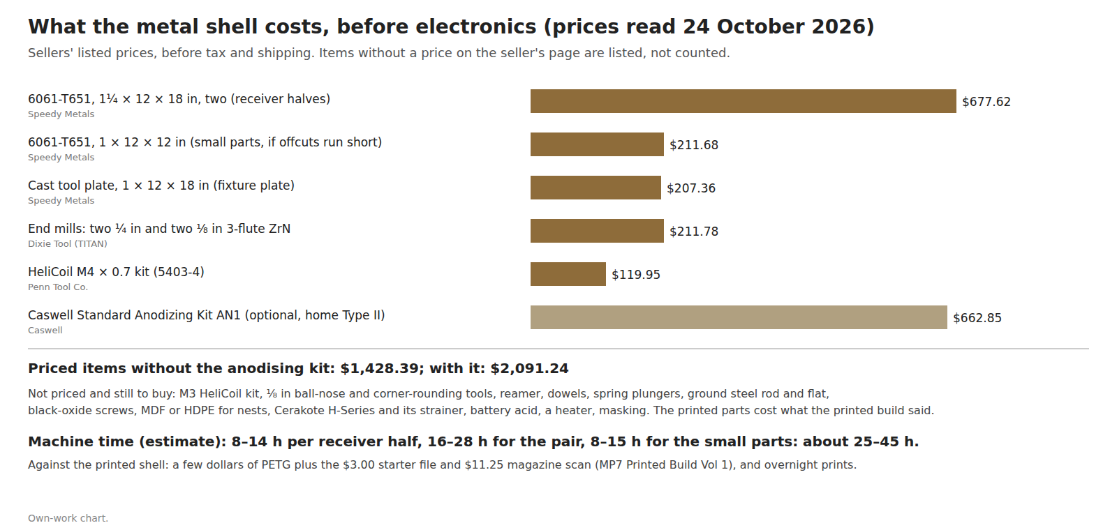
Table 1 — 7.9 What it costs
| Item | Price | Seller, 24 October 2026 |
|---|---|---|
| 6061-T651, 1¼ × 12 × 18 in, two | $677.62 | Speedy Metals |
| 6061-T651, 1 × 12 × 12 in (if offcuts run short) | $211.68 | Speedy Metals |
| Cast tool plate, 1 × 12 × 18 in (fixture) | $207.36 | Speedy Metals |
| TITAN TC63516 ¼ in ×2, TC63508 ⅛ in ×2 | $211.78 | Dixie Tool |
| HeliCoil 5403-4 M4 kit | $119.95 | Penn Tool Co. |
| Priced subtotal | $1,428.39 | |
| Caswell AN1 Standard Anodizing Kit (optional) | $662.85 | Caswell |
| With home anodising | $2,091.24 |
Not priced, still to buy: an M3 HeliCoil kit; ⅛ in ball-nose and corner-rounding tools; a reamer and ground dowels; spring plungers; ground steel rod and flat; black-oxide screws; MDF or HDPE for the nests; Cerakote H-Series black and its 150-mesh strainer ($39.95 on Cerakote’s US page); battery acid, a tank heater and masking supplies if anodising at home. Not counted at all: the electronics, which are the same in every MP7 build and priced in Reference Electronics and the power dives, and the printed parts, which cost what the printed build says.
Against that: the printed shell’s outside costs a few dollars of PETG plus the $3.00 starter STEP and the $11.25 magazine scan (Printed Build Vol 1). The metal gun is, on these figures, roughly a hundred times the printed shell’s material cost, and that is before the machine time.
7.10 How long it takes
Table 2 — 7.10 How long it takes
| Stage | Estimate | Basis |
|---|---|---|
| Re-split the printed design for machining, CAM for every part | Several evenings | The owner’s CAD; not estimated here |
| Coupons (pocket, nest, threads, finish) | One to two days of shop time | Volume 4 §4.10 |
| Receiver halves | 16–28 machine hours for the pair | Volume 4 §4.11 |
| Small parts on the Nomad, mini mill and lathe | 8–15 machine hours | Volume 4 §4.11 |
| Finishing (blast, mask, Cerakote and anodise, cure) | Two to three days elapsed | Volume 6 |
| Assembly, bonding, bench checks | A day | This volume |
About 25 to 45 machine hours, spread over a few weeks of evenings and weekends, against overnight prints for the printed gun.
7.11 Before the first game
Table 3 — 7.11 Before the first game
| Check | Pass |
|---|---|
| The seven rules of Volume 2 on the finished parts: no bore, solid bulkhead, closed cassette bay, solid web above the trigger, solid backplate, cables off the axis, no H&K marks | All, photographed for the design note |
| Continuity between all aluminium parts | Well under 1 Ω |
| Shell to logic ground at the one bond point; no other contact between carrier and shell | One path |
| No continuity between any GX pin except ground and the shell | Open |
| Grommets in every pass-through; no lead touching the moving mass or stock rails | Visual and by hand |
| Kick and current rise measured in the metal receiver (Section 7.6) | Recorded; top joint insulated if needed |
| Shell temperature after the worst game (Section 7.7) | Comfortable in the hand |
| Weight and balance (Section 7.8) | As decided, kick still right |
| Orange sleeve bonded and pinned, at least 6 mm (Volume 6 §6.8) | Always |
| GX plug mated before the brick is plugged in (D31) | Habit |
| House rule D29 for storage and any trip out | Always; cased, out of sight |
7.12 Why this, and why not the others
Table 4 — 7.12 Why this, and why not the others
| Choice | Pick | Status | Why, and why not the others |
|---|---|---|---|
| Shell grounding (MA-11) | Parts bonded together; shell to logic ground at one point near the cable entry; carrier on insulating standoffs; USB shield as WD-4 | Proposed | Static goes down the cable’s ground without crossing the board; one path. Floating shell: discharges through pinholes into the electronics. Bonded at many points: ground current divides through the shell. Bonded to the 24 V return: invites pulse current into the shell |
| Antenna in a wireless metal gun | Printed front sight block via the XIAO’s U.FL lead; W10 decides | Proposed | Clear line to the screen, away from the hand. Inside the metal: shielded. Magazine: hand and pack |
| Shorted turn (MA-12) | Open cassette frame; measure; insulate the top joint only if it matters | Proposed | Costs nothing to test; keeps the bond of MA-11. Ignoring it: unknown loss. Insulating both joints: loses the bond |
| Weight control | Pocketing after operation 1, magazine ballast | Proposed | The shell is the ballast; decide against the measured printed gun |
7.13 What could not be verified
- The size of the shorted-turn loss in this receiver: no source quantifies it for a geometry like this; only the bench can.
- Whether the 50 A supply, the powder-coat oven or an ESD simulator meet this volume’s needs: their details are not recorded.
- The carpet test is not a standard ESD test.
- RSSI through the metal shell for each antenna place: not measured.
- Every cost line is a listed price on one day; tax, shipping and unpriced items are excluded; every hour is an estimate.
Sources
- Fully Wired Vol 5 (grounds, WD-4); Fully Wireless Vols 3, 5 (§5.7) and 6 (W10); Reference Electronics Vol 3; Solenoid Recoil Vols 5, 6 and 7; LiPo Batteries Vol 6; MP7 Printed Build Vols 1, 5 and 7; HK MP7 Vol 4.
- US Patent 4,443,775, “Solenoid actuator”, Shoketsu Kinzoku Kogyo KK (later SMC), filed 6 January 1982, published 17 April 1984, https://patents.google.com/patent/US4443775A/en, read 24 October 2026.
- Protolabs, Aluminum 6061-T651/T6 data sheet (thermal conductivity 167 W/m·K), read 24 October 2026.
- Prices: Speedy Metals (p-2415, p-2416, p-2931), Dixie Tool (TC63516, TC63508), Penn Tool Co. (HeliCoil 5403-4), Caswell (AN1), Cerakote (SE-276 strainer, shown on the H-190 Armor Black page), all read 24 October 2026.
Comments (0)