MP7 Light Gun: Machined Aluminum · Volume 5
Threads, Fasteners and Mechanisms in Metal
What changes when the printed gun's heat-set inserts and printed channels become aluminium: tapped and form-tapped threads against helical inserts, bosses sized for engagement, screws and galvanic pairs, dowels reamed as a pair, the backplate's locking pins, steel stock rails in anodised channels, the foregrip hinge, the kick cassette bolted through the ribs, and the mounts for the carrier and camera
5.1 What carries over, and what does not
The printed build designed the gun’s mechanisms: a stock on metal rails with a spring plunger at each position, a foregrip on a steel pivot with a detent at each end, bought Picatinny rails, a dummy magazine with a reload magnet and the GX plug, and a kick module on its own plate (MP7 Printed Build Vol 5 §§5.4, 5.6, 5.8). Those designs carry over unchanged in function. What changes is how they attach: every heat-set insert, printed boss and printed channel in the printed gun (Vol 6 §6.3) becomes a thread, an insert or a machined feature in aluminium, and metal brings two new problems, galling and galvanic contact, that plastic never had.
5.2 Threads straight into aluminium
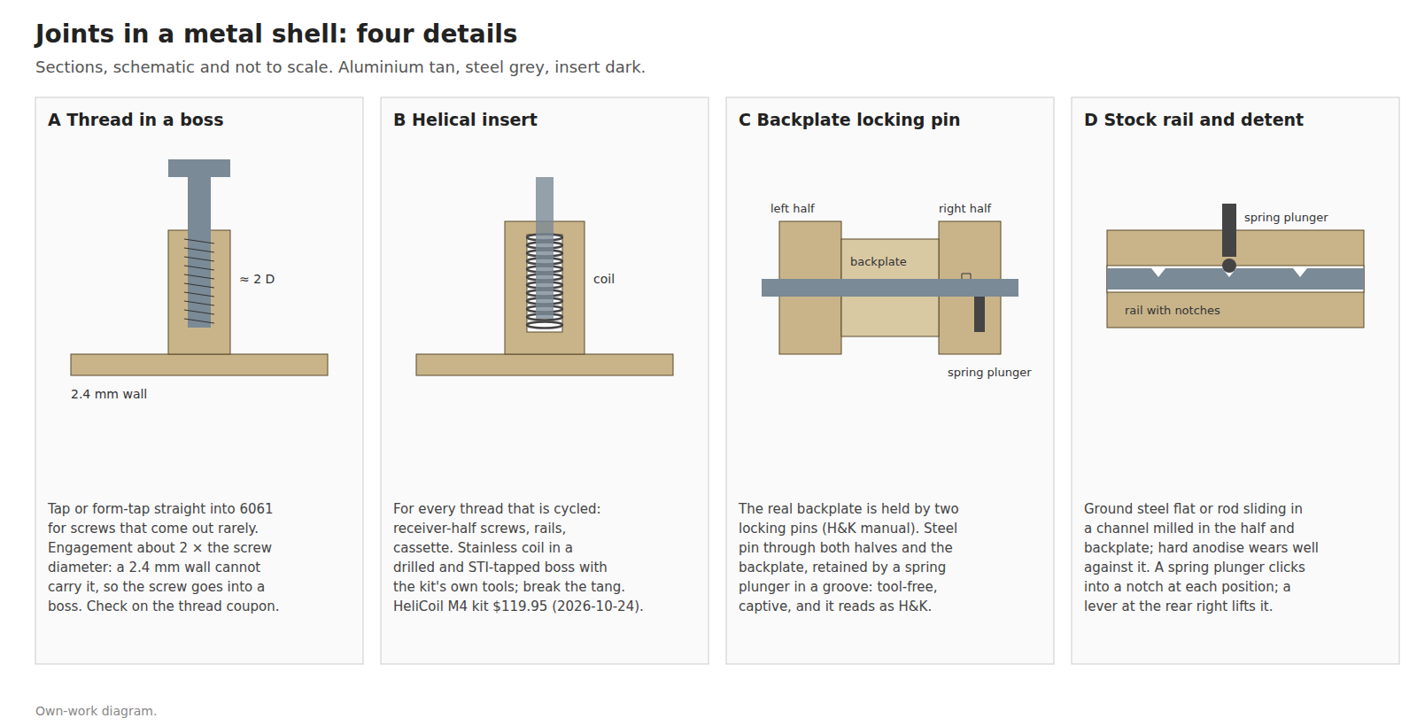
6061-T6 takes a good cut thread, and a form tap (a fluteless tap that rolls the thread rather than cutting it) makes a stronger, chip-free one in a slightly larger pilot hole. Either is right for screws that come out a handful of times in the gun’s life: the carrier’s standoffs, the camera housing, the trigger module, the grip panels.
Tapped aluminium threads wear and gall when a steel screw is driven in and out many times, and a stripped thread in a finished receiver half is a serious repair. So threads that will be cycled get inserts (Section 5.3).
Two practical points. Tap before anodising and mask or plug the holes, or chase them after: anodise builds on the thread flanks (Volume 6), and a Type III coat can be thick enough to bind a screw. Never tap after Cerakote without masking; the coating fills fine threads.
5.3 Helical inserts
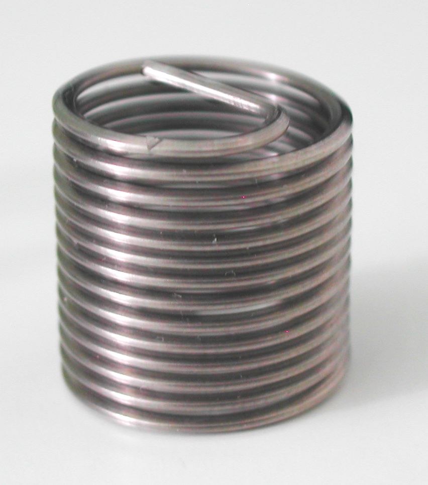
A helical insert is a coil of stainless wire with a diamond section that screws into a hole tapped with an oversize STI (screw thread insert) tap and gives an internal thread of the nominal size. It spreads the screw’s load over a larger diameter of aluminium and gives a steel-on-steel thread that does not wear.
- Where: the screws that join the receiver halves, the rail screws, the kick cassette’s screws, and any thread opened for service.
- What: a HeliCoil kit carries the drill, STI tap, inserting tool and inserts for one size. The HeliCoil 5403-4 kit, M4 × 0.7 with 6 mm inserts, was $119.95 at Penn Tool Co. on 24 October 2026, with 18 inserts. An M3 kit is the other size likely to be needed; it was not priced.
- How: drill and STI-tap on the 3990, square to the face, before anodising; install inserts after the finish; break the tang and remove it, so it cannot fall into the gun.
- Why not key-locking inserts (solid inserts held by keys or a locking ring): stronger, but they need a larger hole and wall than a 2.4 mm shell’s bosses can give. Why not press-in or heat-set inserts: those are for plastics. Why not threads straight into every hole: wear and galling, Section 5.2.
5.4 Bosses, not walls
The common design rule for a steel screw in aluminium is a thread engagement of about twice the screw’s diameter, so that the screw breaks before the aluminium thread strips. An M4 screw wants about 8 mm of engaged thread; a 2.4 mm wall gives a third of that. Every screw goes into a boss, a column rising from the wall or floor, long enough for the engagement and with at least a couple of millimetres of aluminium round the hole (or round the insert’s outside diameter). The coupon in Volume 4 §4.10 checks the rule on the actual plate: tap a boss, drive the intended screw to well past its working torque, and see which gives.
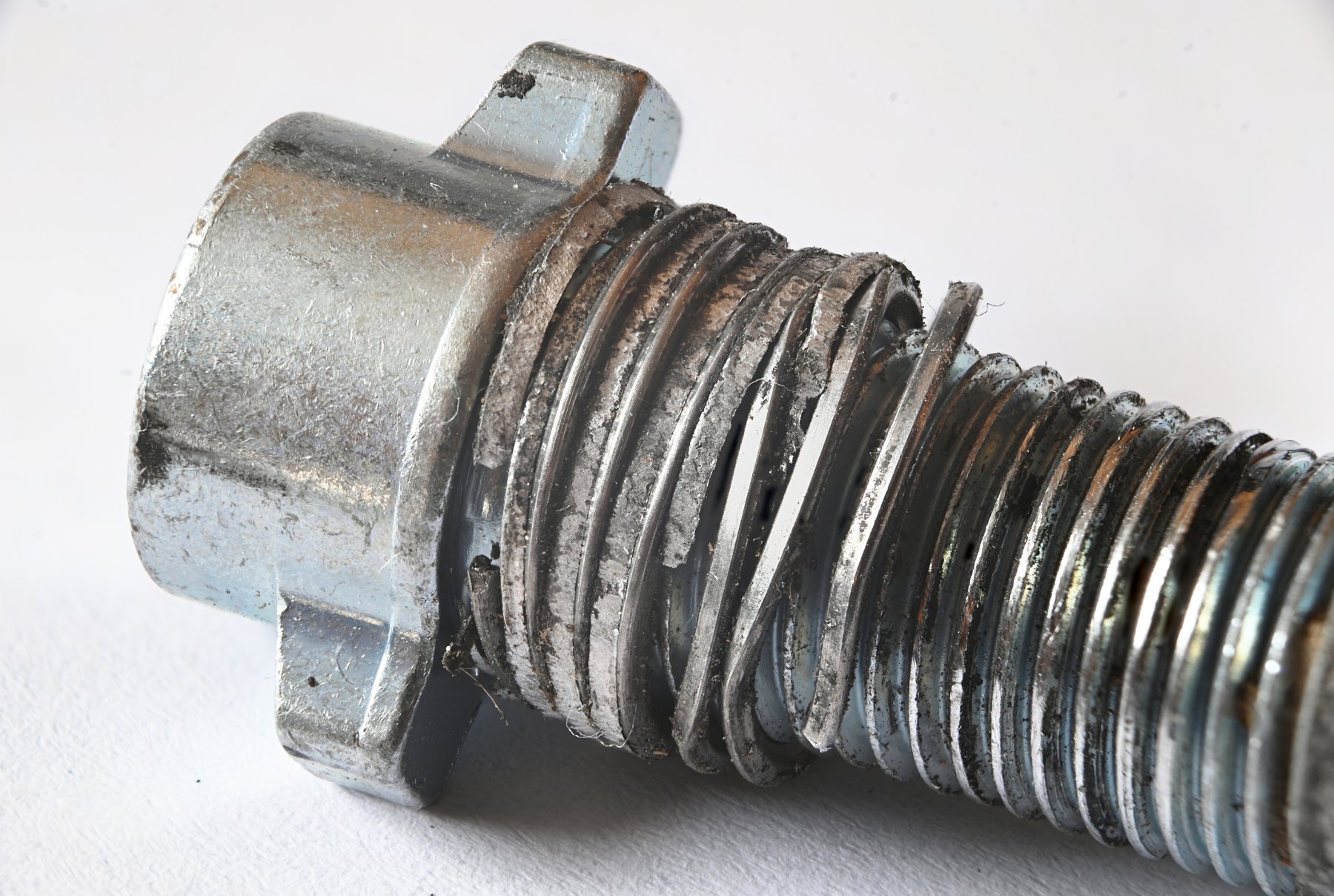
The failure the rule guards against is not the insert letting go but the parent aluminium shearing round it:
5.5 Screws, and metal against metal
Screws. Socket head and button head cap screws, metric, from the left side of the gun as in the printed build, so the ejection-port side stays clean. Two choices of material:
- Black-oxide alloy steel: strong, black, and close in look to the real gun’s dark fittings. It rusts if the black oxide wears, which inside a gun kept indoors is slow.
- Stainless (A2): no rust, but softer, and stainless on aluminium threads is the classic galling pair.
The proposal is black-oxide alloy steel screws into helical inserts (which are themselves stainless, so the thread pair is steel on stainless, not steel on aluminium), with a drop of medium thread-locker on the screws that see the kick.
Galvanic contact. Steel or stainless against aluminium is a galvanic pair, and in a wet or salty environment the aluminium corrodes at the contact. In a gun kept indoors and handled with dry hands it is a minor concern, and anodise is an insulator that breaks the circuit everywhere except in the threads and at bare machined faces. A light film of anti-seize or grease on screws and dowels, and keeping the gun dry, is enough.
Steel sliding on aluminium. Bare aluminium against steel galls. The stock rails’ channels and the foregrip hinge’s bores are hard-anodised (Type III) if the finish allows it (Volume 6), or at least anodised, and lubricated with a dry PTFE or a light grease. Type III’s hard, wear-resistant surface is exactly what a sliding steel part wants.
5.6 Holding the halves together
- Dowels. Two or three 3 mm ground steel dowel pins across the joint face, in holes reamed through both halves clamped together on the 3990 (Volume 4 §4.9), press fit in one half and a slip fit in the other. They locate; the screws clamp.
- Screws through the cross ribs. Volume 2’s rule 3 put solid cross ribs ahead of and behind the kick cassette. They are the natural place for the half-joining screws, each into a helical insert in the right half, along with screws through the bosses round the grip core and at the backplate end.
- The joint face is finished flat in operation 1 (Volume 4) and is the datum for both halves. It is masked from Cerakote (Volume 6) so the halves close metal to metal, with no paint film to creep and loosen.
5.7 The backplate’s locking pins
On the real gun the backplate, with the buffer, charging handle and stock, is held to the receiver by two locking pins, and the receiver has storage holes for the pins (H&K’s manual, keys 16 and 17, as reproduced in HK MP7 Vol 5). Reproducing that arrangement costs little and is one of the details that makes the gun feel right in the hand:
- Steel pins ground to a slip fit through both receiver halves and the backplate, retained by a spring plunger that clicks into a groove near the pin’s head (joint C in the figure).
- Backplate removal gives access to the kick cassette and the carrier without opening the halves.
- The pins carry no firing load because nothing fires. They hold an aluminium block in place against the solenoid’s reaction, which the cassette’s own screws carry first.
- No buffer bore in the backplate (Volume 2, rule 5); the stock rails and the latch are its only internal features.
5.8 Stock rails and the detent
The real stock is a pair of rails ending in a butt plate that slide into the receiver alongside the bolt’s path and lock in each position, released by a lever at the rear right (HK MP7 Vol 5, as the printed build records). In metal:
- Rails: ground steel flat bar or rod cut to the starter’s section on the lathe and 3990, with a notch at each stock position. Steel because the rail’s edges take the wear and the loads of a gun pulled to the shoulder.
- Channels: milled in the receiver halves and the backplate in operation 1, hard-anodised and lubricated, with a sliding clearance drawn from the coupon (Volume 4).
- Detent: a spring plunger in the backplate clicks into each notch (joint D); a small lever at the rear right lifts it. A commercial spring plunger is simpler and more repeatable than a ball and spring in a drilled hole.
- Butt plate: 6061, Nomad-cut, with the rails pinned into it.
The rails pass beside the kick cassette, as they pass beside the bolt on the real gun. The cassette and the channels are drawn together so a rail never touches the moving mass.
5.9 The foregrip hinge
The real folding grip, in H&K’s words, is “slightly locked” folded and “firmly locked” extended (HK MP7 Vol 5). The printed build gives it a steel pivot and a ball detent at each end of travel. In the metal gun:
- A hinge block of 7075 (Volume 3) screwed to the front of the receiver, with a bushed bore for a steel pivot pin.
- The grip body itself printed in the textured polymer of the real one, on an aluminium or steel tang that pivots in the block.
- Two detents: a strong spring plunger for the extended position, a light one for folded. Two different plunger forces give exactly the “firmly” and “slightly” of the manual.
5.10 Kick cassette, carrier, camera, trigger
- Kick cassette (ME-5, Moving Ejection Port Vol 6). Bolted into its square bay through the cross ribs with thread-locked screws into helical inserts. Every impact now goes straight into the receiver. Keep the printed build’s TPU stops (ME-4) to soften the noise, which a metal receiver transmits and radiates better than a plastic one (Solenoid Recoil Vol 5 on noise). And keep any closed aluminium loop away from round the coil’s axis, which Volume 7 explains.
- Carrier board (D44). Standoffs on machined bosses rising from the flat deck finished in operation 1. The IMU wants the board “rigid to the receiver” (Positional and Inertial Vol 6); a machined deck gives that. The standoffs are insulating (nylon or a nylon shoulder washer on a metal standoff) unless and until the bonding scheme in Volume 7 says otherwise: a board ground pad screwed straight onto a metal shell is a ground connection whether intended or not.
- Camera. The camera housing and front sight block stay printed (Volume 3) and bolt to the aluminium front cover. The rules for the aperture and alignment are the printed build’s and Reference Electronics’ (Printed Build Vol 5 §5.2, Reference Electronics Vol 3). A metal front cover makes the housing’s datum face truer and keeps it square after many shots.
- Trigger module. A self-contained printed or machined housing with its own pivot, spring and Hall sensor, screwed into a plain opening (Volume 2, rule 4; Controls and Inputs). Aluminium is non-magnetic and does not disturb the Hall sensor’s field; steel screws and pins near the magnet can, so keep them out of the magnet’s immediate neighbourhood, as in the printed gun.
- Magazine catch and reload sensor. Unchanged from the printed build: the catch in the grip core, the magnet in the printed magazine, the sensor in the grip.
5.11 Why this, and why not the others
Table 1 — 5.11 Why this, and why not the others
| Choice | Pick | Status | Why, and why not the others |
|---|---|---|---|
| Threads that are cycled (MA-8) | Stainless helical inserts (HeliCoil type), M3 and M4 | Proposed | Steel thread, no wear or galling, small boss. Key-locking: too large for the bosses. Heat-set: for plastics. Bare tapped holes: wear and gall |
| Threads used rarely | Cut or form-tapped 6061 | Proposed | Simple; form taps give stronger threads |
| Engagement | About 2 × D, in bosses | Proposed | Common rule for steel screws in aluminium; coupon-checked |
| Screws | Black-oxide alloy steel, thread-locker on kick-loaded screws | Proposed | Strong, dark, steel-on-stainless with inserts. Stainless screws: gall in aluminium |
| Half alignment | Ground dowels reamed as a pair | Proposed | Repeatable alignment; screws only clamp |
| Backplate retention | Two steel locking pins with spring plungers | Proposed | H&K’s own arrangement; tool-free access to the cassette and carrier |
| Stock rails | Ground steel with notches, spring plunger, hard-anodised channels | Proposed | Wear and strength; plunger more repeatable than a loose ball |
| Foregrip | 7075 hinge block, steel pin, two plungers of different force | Proposed | Gives the manual’s “firmly” and “slightly locked” |
| Carrier standoffs | Insulating until Volume 7’s bonding is settled | Proposed | A ground pad on a metal shell is an unplanned ground connection |
5.12 What could not be verified
- The thread engagement rule’s exact factor for 6061-T6: a common design rule, not read from a fastener maker’s data here; the coupon checks it.
- The M3 HeliCoil kit’s price and part number, and the STI drill sizes: to be taken from the kit bought.
- The real gun’s pin diameters and stock-rail section: not looked up; the starter’s outside and the own geometry decide.
- Spring plunger forces for the two foregrip positions: to be chosen on the bench.
Sources
- MP7 Printed Build Vols 5 (§§5.2, 5.4, 5.6, 5.8) and 6 (§6.3); HK MP7 Vol 5 (“The stock, the grip and the charging handle”, H&K’s manual figure keys); Moving Ejection Port Vol 6; Positional and Inertial Vol 6; Solenoid Recoil Vol 5.
- Penn Tool Co., “HeliCoil Screw Thread Insert Thread Repair Kit #5403-4, M4x0.7 Metric Threads, 6mm Insert Length”, $119.95, https://penntoolco.com/helicoil-screw-thread-insert-thread-repair-kit-5403-4-m4x0-7-metric-threads-6mm-insert-length-61-785-2, read 24 October 2026.
- Wikimedia Commons: “Helicoil 14x1.25.jpg”, User:cav, public domain; “Failed threaded insert in cast aluminium.jpg”, Phiarc, 16 September 2021, CC BY-SA 4.0 (“Axial shear failure of a threaded insert (helicoil-style) in a cast aluminium part”).
Comments (0)