IR Point Tracking · Volume 1
The Camera That Sees Only Dots — How a Multi-Object Tracking Sensor Works
Markers at the screen and a camera in the gun: what happens on the sensor die every frame, what the Wii-class camera and the PixArt PAJ7025 actually report, how 128 pixels become 1,024 coordinates, and the frame-subtraction feature no light gun uses yet
1.1 The Method in One Paragraph
Put a few infrared emitters at known places around the screen. Put a small camera in the gun, looking along the barrel. The camera finds the emitters as bright points in its field of view; where those points fall in the camera’s image, relative to the image centre, tells the firmware where on the screen the barrel is pointing. The screen itself plays no part, so the method works on any television, monitor or projector, which is why it replaced CRT raster timing once flat panels took over (History of Light Guns, Volume 7 tells that story, and the CRT Timing dive the method it replaced).
This dive is about the sensing half: what the camera is, what it measures, what the emitters must do to be measured, what geometry the points need, how field of view, distance and screen size trade against each other, and what in a living room fools it. Two sibling dives own the neighbouring ground and are linked rather than repeated. Reference Electronics chooses and wires the parts: the camera module (Volume 3) and the emitter bar (Volume 6). Open-Source Firmware describes what OpenFIRE does with the points once it has them (Volume 2). The mathematics of turning four points into an aim point, in depth, belongs to Aiming Maths and Calibration; Volume 3 here gives only the sensing side of it.
1.2 What “Multi-Object Tracking” Means
PixArt, which makes the sensor in the Wii Remote and its successors, calls the device class a multiple objects tracking (MOT) sensor. Its PAJ7025R2 datasheet describes the part as a module “which integrates a high quality CMOS image sensor, image processor and Digital Signal Processor (DSP)”, and goes on:
“Upon grayscale image is captured, the PAJ7025R2 immediately process and produce relevant output information. The output information consist of object area, object center coordinate, 4-way object boundary, average/maximum object brightness, object radius, object range, and aspect ratio. The communication interface is through SPI.”
WiiBrew, the reverse-engineering wiki of the Wii homebrew community, says the same of the Wii Remote’s camera from the outside: “The camera’s built-in image processing is capable of tracking up to 4 moving objects, and these data are the only data available to the host. Raw pixel data is not available to the host, so the camera cannot be used to take a conventional picture.”
That is the whole point of the design. A 98 by 98 image at 200 frames a second is about 1.9 million pixels a second; four objects at a few bytes each are a few kilobytes a second. The reduction happens on the sensor, so a small microcontroller on a slow bus can track the points at the sensor’s full frame rate with almost no processing of its own. It is also the design’s limitation: the host can never look at the scene to find out why a point is where it is. A reflection, a lamp and an emitter look identical in the report, and every interference problem in Volume 5 follows from that.
The same idea run backwards, with markers on the controller and the camera at the screen, is how the PlayStation Move and several virtual-reality headsets track; a light gun puts the camera in the hand because the gun is what must know where it points.
1.3 Inside the Sensor, Stage by Stage
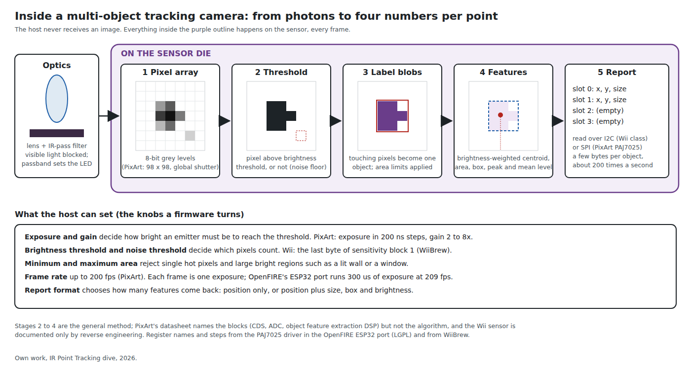
Neither maker publishes the algorithm. PixArt’s block diagram names the blocks (a 98 × 98 pixel array, correlated double sampling, an ADC, and “Object Detection” containing “Object Feature Extraction DSP”); WiiBrew documents the Wii camera only as far as its registers and outputs. What follows is the standard method that those blocks and outputs imply, with the published facts attached to each stage.
- Optics. A lens and an infrared-pass filter. The filter is the first line of defence: it removes visible light, so a white wall lit by a lamp is dim to the sensor while a black-epoxy LED that looks dark to the eye is bright. The passband decides which LED wavelength works (Volume 2). In the Wii Remote there are two filters: the dark plastic window in the case and, inside the camera module, “a teensy slab of dichroic-coated glass … (of unknown optical properties)” (WiiBrew).
- Pixel array. A monochrome sensor: 128 × 96 in the Wii camera (WiiBrew), 98 × 98 of 11 µm pixels in the PixArt PAJ7025, read out at 8 bits per pixel with a global shutter (PAJ7025R2 datasheet). Global shutter means every pixel integrates over the same interval, so the four points in one frame are four points at one instant (1.7).
- Threshold. Each pixel is compared with a brightness threshold, and a separate noise threshold rejects isolated faint pixels. Both are registers (1.8).
- Labelling. Touching above-threshold pixels are grouped into one object. Objects smaller than a minimum area are dropped as noise; objects larger than a maximum area are dropped as not-a-point (a window, a lamp shade, a sunlit wall). The PixArt driver sets both limits.
- Features and report. For each surviving object the sensor computes a centre (to a fraction of a pixel, 1.6), an area, a bounding box and brightness figures, and places it in an output slot that the host reads over I2C (Wii class) or SPI (PixArt).
The consequences for a gun designer are direct. The threshold and area limits are the only “intelligence” the sensor has for telling an emitter from anything else; the host’s only further defences are geometry (four points in a plausible quadrilateral) and the brightness and size figures in the richer report formats.
1.4 What the Wii-Class Camera Reports
The DFRobot SEN0158 module and the camera salvaged from a Wii Remote are the same class of sensor and speak the same register protocol; their physical and electrical details are in Reference Electronics, Volume 3. WiiBrew documents three report formats, selected by writing a mode number to register 0x33 of the camera’s block:
Table 1 — The DFRobot SEN0158 module and the camera salvaged from a Wii Remote are the same class of sensor and speak the same register protocol; their physical and electrical details are in [Reference Electronics, Volume 3](/light-guns/building-the-electronics/reference-electronics/vol-3/). WiiBrew documents three report formats, selected by writing a mode number to register 0x33 of the camera's block
| Format | Mode | Bytes, four objects | Per object | Source |
|---|---|---|---|---|
| Basic | 1 | 10 | X (0 to 1023) and Y (0 to 767), 10 bits each; two objects packed into 5 bytes | WiiBrew |
| Extended | 3 | 12 | X, Y and “a rough size value”, 0 to 15 | WiiBrew |
| Full | 5 | 36 | X, Y, size, “the bounding box of the pixels included in the blob” (minimum and maximum X and Y, 7 bits each, in sensor pixels) and “a deeper intensity value”, 8 bits | WiiBrew |
The DFRobot library that OpenFIRE v6.2 uses reads the Basic format, 11 bytes with its header byte (Open-Source Firmware, Volume 2). The OpenFIRE ESP32 port, which also drives the same camera, now reads the Full format, because its newer tracking code and its IR test screen use the box and intensity. Its source records one measurement worth having: the Full-format intensity of an LED emitter runs “about 4..30, 4 at the detection limit, measured by the LIGHTGUN-STUDIO project”, a much smaller range than the 8-bit field suggests.
Three behaviours of the slots matter to anyone writing tracking code, and all three are WiiBrew’s:
- First free slot. “When the IR camera identifies an object, it assigns it to the first available object slot.”
- Slots are sticky. “If an object moves out of view, its slot is marked as empty (returns 0xFF data), but other objects retain their slots. For example, if the camera is tracking two objects and the first moves out of view, the data returned will be [empty, second object, empty, empty].” The slot number is therefore not an identity: it says nothing about which emitter an object is. The firmware must work that out from geometry, which is what OpenFIRE’s quadrant sort does.
- A fifth object. “With more than four objects visible, the camera is prone to rapidly switching between some of them.” A single reflection is enough to make one of the four real emitters drop in and out from frame to frame.
An empty slot reads as 1023 in the libraries’ units, which is how firmware recognises “not seen” (Reference Electronics, Volume 3).
1.5 What the PixArt PAJ7025 Reports
The PAJ7025R2 and R3 are the same sensor behind different lenses (Reference Electronics chose the R3 as the kit camera, decision D18; Volume 3 of that dive has the comparison). They track up to 16 objects and report each with fifteen fields. The field list below is taken from two independent drivers that agree: Bart Trzynadlowski’s pa_driver for the PAJ7025R2 (GitHub, trzy/PixArt) and Alessandro Satanassi’s LGPL PixArt_PAJ7025 library in the OpenFIRE ESP32 port. Both decode the same 16-byte record.
Table 2 — 1.5 What the PixArt PAJ7025 Reports
| Field | Width | What it is |
|---|---|---|
| area | 14 bits | pixels in the object; 0 means the slot is empty |
| cx, cy | 12 bits each | centre, 0 to 4095 |
| average brightness, maximum brightness | 8 bits each | mean and peak grey level of the object’s pixels |
| range | 4 bits | not defined in either driver |
| radius | 4 bits | not defined in either driver |
| boundary left, right, up, down | 7 bits each | bounding box in sensor pixels (0 to 97) |
| aspect ratio | 8 bits | presumably of the object; the datasheet has a section 7.8.2 on “Bar Shape Object Orientation Ratio” that was not in the copy read |
| vx, vy | 8 bits each | not defined in either driver; by the names, a velocity |
Two report sizes exist in the ESP32 port’s driver: an extended record of 16 bytes per object read from register bank 5, and a basic record of 6 bytes (area and centre only) from bank 9. Trzynadlowski’s driver reads four formats of 256, 96, 144 and 208 bytes from banks 5, 9, 10 and 11, which matches the datasheet’s “Support 4 types of output format”. The OpenFIRE ESP32 port reads four objects, not sixteen, because its tracking uses four emitters.
Compared with the Wii class, the PAJ7025’s report is far richer. Average and maximum brightness, area and the box are exactly the figures a firmware needs to reject a fifth object on its merits rather than its position: a reflection is usually dimmer and often a different size or shape from the emitter it mirrors (Volume 5).
1.6 Sub-Pixel Resolution
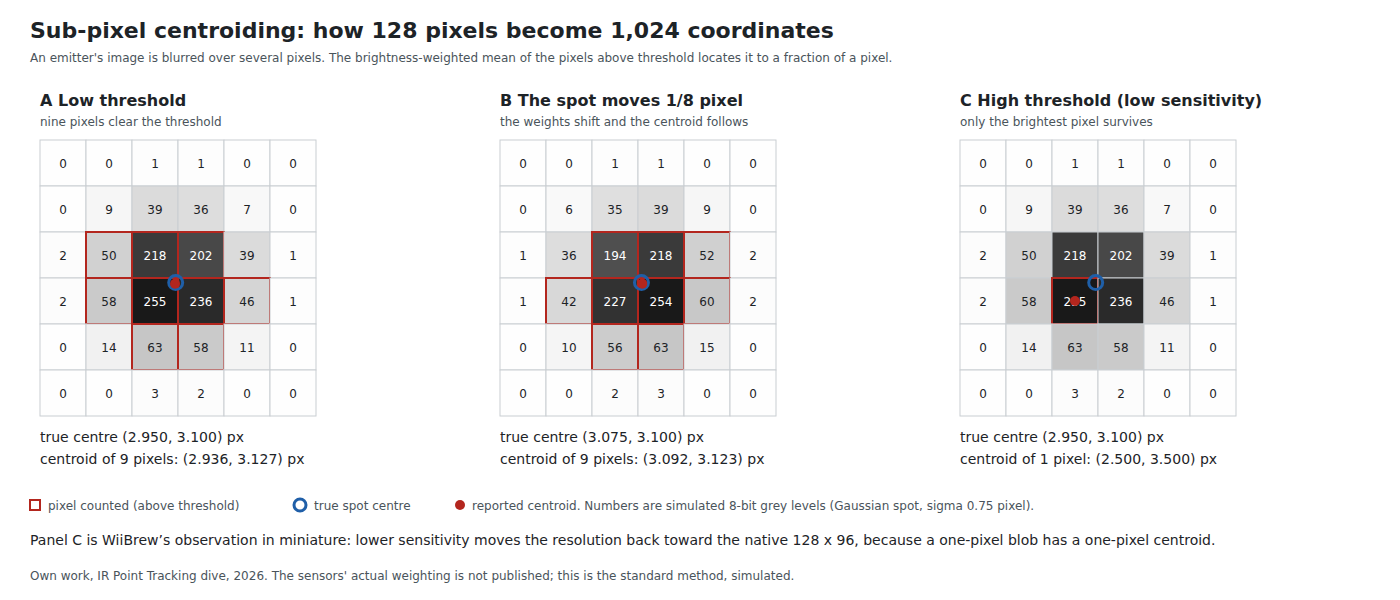
WiiBrew: “The built-in processor uses 8x subpixel analysis to provide 1024x768 resolution for the tracked points.” The PixArt part reports 4096 × 4096 coordinates from 98 × 98 pixels, about 42 counts per pixel. Neither figure is a resolution in the sense of a repeatable measurement; both are the number of steps the centroid arithmetic is allowed to express.
How fine the centroid really is depends on two things the figure shows. The emitter’s image must spread over several pixels, so that moving it a fraction of a pixel changes the weights; and enough of those pixels must clear the threshold. WiiBrew states the consequence for the Wii camera directly: “Setting the sensitivity as high as possible, without unwanted light being tracked, is recommended to achieve the highest subpixel resolution. As the sensitivity is reduced, the subpixel resolution also reduces, approaching the true sensor resolution of 128x96.” That is why the OpenFIRE instruction book’s advice to run sensitivity “as high as possible” (Open-Source Firmware, Volume 5) is about resolution and not only about range: a dim emitter, or a high threshold, gives a cursor that moves in coarse steps.
It also means the 42 counts per pixel of the PixArt report are not 42 real steps per pixel. The repeatable resolution is set by noise in the pixel values, which no datasheet in hand quantifies. It is a bench measurement: hold the gun still in a fixture and record the standard deviation of each point’s coordinates (Volume 6).
1.7 Exposure, Frame Rate and Shutter
The PAJ7025’s frame rate is programmable from 10 to 200 frames per second, its exposure separately, and its gain from 2 to 8 times (R2 datasheet). The OpenFIRE ESP32 port sets the frame rate to 209 per second (matching the Wii camera’s measured rate; whether the PixArt part honours a request above its 200 fps rating is not stated) and the exposure to 300 µs. The register arithmetic in the port’s driver shows the units: the frame period is written in 100 ns steps (10000000 / fps) and the exposure in 200 ns steps (exposure_µs × 5).
So each 4.8 ms frame contains 0.3 ms of light collection, about 6 % of the time. Three things follow:
- Motion blur is small. A fast swing of the gun at 180° a second moves the image by 0.054° in 300 µs, about a fifth of a Wii-class pixel and a thirtieth of an R3 pixel. Over a whole 4.8 ms frame it would be 0.86°.
- The ratio of emitter to ambient light does not depend on the exposure. A lamp and an emitter both integrate over the same 300 µs, so a shorter exposure dims both equally. What a short exposure does allow is an emitter driven much harder during that window than its continuous rating, if the emitter can be told when the window is (1.9).
- A global shutter keeps the quadrilateral honest. With a global shutter all four points are sampled at the same instant, so a moving gun produces a correctly shaped quadrilateral. A rolling shutter samples each row at a different time, so a gun moving vertically would see a skewed one. Whether the Wii camera’s shutter is global or rolling is not published.
1.8 The Sensitivity Knobs Side by Side
The two sensor families expose their thresholds differently.
Wii class. Sensitivity is two register blocks, 9 bytes and 2 bytes. WiiBrew: “The last byte of Block 1 determines the intensity sensitivity, with increasing values reducing the sensitivity. Both bytes of Block 2 must be zero for the full sensitivity range to be available.” The meaning of the other bytes is not documented. The values the firmware community uses (Marcan, inio and Kestrel’s settings, and Nintendo’s own five levels) are tabulated on WiiBrew, and OpenFIRE’s three levels are reproduced in Open-Source Firmware, Volume 2. The Wii console’s own levels raise the last byte of Block 1 from 0x20 at level 5 to 0xfe at level 1; the community’s maximum-sensitivity setting uses 0x0C and a zero Block 2.
PixArt. The port’s driver exposes the knobs by name: setGain(global, ggh), setExposure(µs), and setDSP(area_min, brightness_th, area_max, noise_th). Its presets, read from OpenFIRECamera.cpp on 2026-10-19:
Table 3 — PixArt. The port's driver exposes the knobs by name: setGain(global, ggh), setExposure(µs), and setDSP(areamin, brightnessth, areamax, noiseth). Its presets, read from OpenFIRECamera.cpp on 2026-10-19
| Camera | Level | Gain registers | Area min | Brightness threshold | Area max | Noise threshold |
|---|---|---|---|---|---|---|
| PAJ7025R2 | 0 | 0x10, 0x00 | 2 | 130 | 150 | 40 |
| PAJ7025R2 | 1 | 0x10, 0x02 | 2 | 130 | 200 | 50 |
| PAJ7025R2 | 2 | 0x10, 0x03 | 1 | 150 | 300 | 60 |
| PAJ7025R3 | 0 | 0x10, 0x02 (“4x”) | 1 | 130 | 150 | 40 |
| PAJ7025R3 | 1 | 0x08, 0x03 (“6x”) | 1 | 130 | 200 | 50 |
| PAJ7025R3 | 2 | 0x10, 0x03 (“8x”) | 1 | 130 | 300 | 60 |
The R3 rows carry the author’s own caveat: “Initial R3 presets to validate on hardware, keeping 300 us exposure.” Two things in them are worth reading closely. Every R3 level runs at 4× gain or more, while the R2’s lowest runs at the base gain; Volume 2 shows why the wide lens needs it (the R3 collects about one thirty-ninth of the R2’s light from the same emitter). And the maximum area of 150 to 300 pixels, out of 9,604 in the array, is the setting that turns away a sunlit wall: a blob bigger than that is not reported at all.
1.9 Frame Subtraction and the LED Sync Pin
The PAJ7025R2 datasheet lists, among its key features, “Frame subtraction function”, and its block diagram has an “External LED Control” block driving a pin, G13/LED_SIDE, described in the pin table as “G13 or LED Sync … Can be programmed as LED output pin via register.” A second pin can be programmed as a VSYNC output, and a third as a trigger input for its Frame On Demand mode. The table of contents lists a figure titled “LED_On control signal for frame subtraction”. The pages that describe the mechanism are not in the partial copy that could be read, so the detail is unconfirmed; the principle the names describe is the classic one. The sensor takes alternate frames with its own LED on and off, subtracts them, and tracks what is left. Anything that is equally bright in both frames, which is to say all ambient light, cancels.
PixArt built this for products where the emitter travels with the camera: the datasheet’s applications include a “Whiteboard Interactive Pen”, and it notes that the tracked object may be “a direct Infra-Red (IR) light source or indirect with passive IR reflector light source”. A light gun has the arrangement the other way round. The emitters are at the screen, two metres from the sensor that would have to switch them, so no published light gun firmware uses frame subtraction. There are two ways it could be used, and both are open questions for the Experimental Sensing dive:
- A synchronised bar. The gun tells the bar when its exposure is, over a wire or a radio link, and the bar flashes only then. That also allows the bar to be pulsed far beyond its continuous rating (the SFH 4547 takes 1 A for up to 400 µs at low duty, against 100 mA continuous; Reference Electronics, Volume 6), raising the emitter against the background by the same factor. Reference Electronics rejected pulsing because OpenFIRE has no synchronisation; this is what synchronisation would need.
- Retroreflective markers and a light on the gun. Four passive retroreflectors at the screen, an 850 nm illuminator beside the camera driven from the sensor’s own LED pin, and frame subtraction. No cable or power at the screen. Whether retroreflectors return enough light from two or three metres is the bench question.
1.10 What Could Not Be Verified
- The algorithm inside either sensor (labelling, centroid weighting). The stages in 1.3 are the standard method, not a published description.
- The meaning of the PAJ7025’s range, radius and vx/vy fields, and the frame-subtraction mechanism; the datasheet sections that define them were not in the copy read.
- The meaning of the Wii camera’s sensitivity Block 1 bytes other than the last, its shutter type and its filter passband (WiiBrew calls the internal filter “of unknown optical properties”).
- Whether the PAJ7025 honours a 209 fps request above its 200 fps rating.
- The repeatable (noise-limited) resolution of either camera. Volume 6 sets out how to measure it.
Sources
- PixArt Imaging, PAJ7025R2 Product Datasheet, version 1.3, 21 November 2019: general description, key features, block diagram (Figure 2), signal pin table (Table 1), optical specifications (Table 6), IR filter response (Figure 4), table of contents. Marked “PixArt Confidential”; a 20-page partial copy reproduced in alextrical/PAJ7025-KiCad-Library on GitHub was read on 2026-10-19. Not stored in the Library; a kit maker obtains it from PixArt.
- WiiBrew wiki, Wiimote, section “IR Camera” (optical characteristics, initialisation, sensitivity settings, data formats), https://wiibrew.org/wiki/Wiimote, wikitext read 2026-10-19.
- WiiBrew wiki, Sensor Bar, https://wiibrew.org/wiki/Sensor_Bar, read 2026-10-19.
- Bart Trzynadlowski, PixArt (GitHub, trzy/PixArt):
code/arduino/pa_driver/pixart.cpp,pixart_object.hpp,pixart_object.cpp, and README, read 2026-10-19. - Alessandro Satanassi, OpenFIRE-Firmware-ESP32 (GitHub, main branch):
lightgun/lib/PixArt_PAJ7025/PixArt_PAJ7025.hand.cpp(LGPL),lightgun/src/OpenFIRECamera.cpp,lightgun/lib/OpenFIREPosition/OpenFIRECameraProfile.h, read 2026-10-19. - TeamOpenFIRE, OpenFIRE-Firmware v6.2,
libraries/DFRobotIRPositionEx/, as read for Open-Source Firmware, Volume 2. - ams OSRAM, SFH 4547 datasheet v1.7 (2022-08-08), pulsed rating, as tabulated in Reference Electronics, Volume 6.
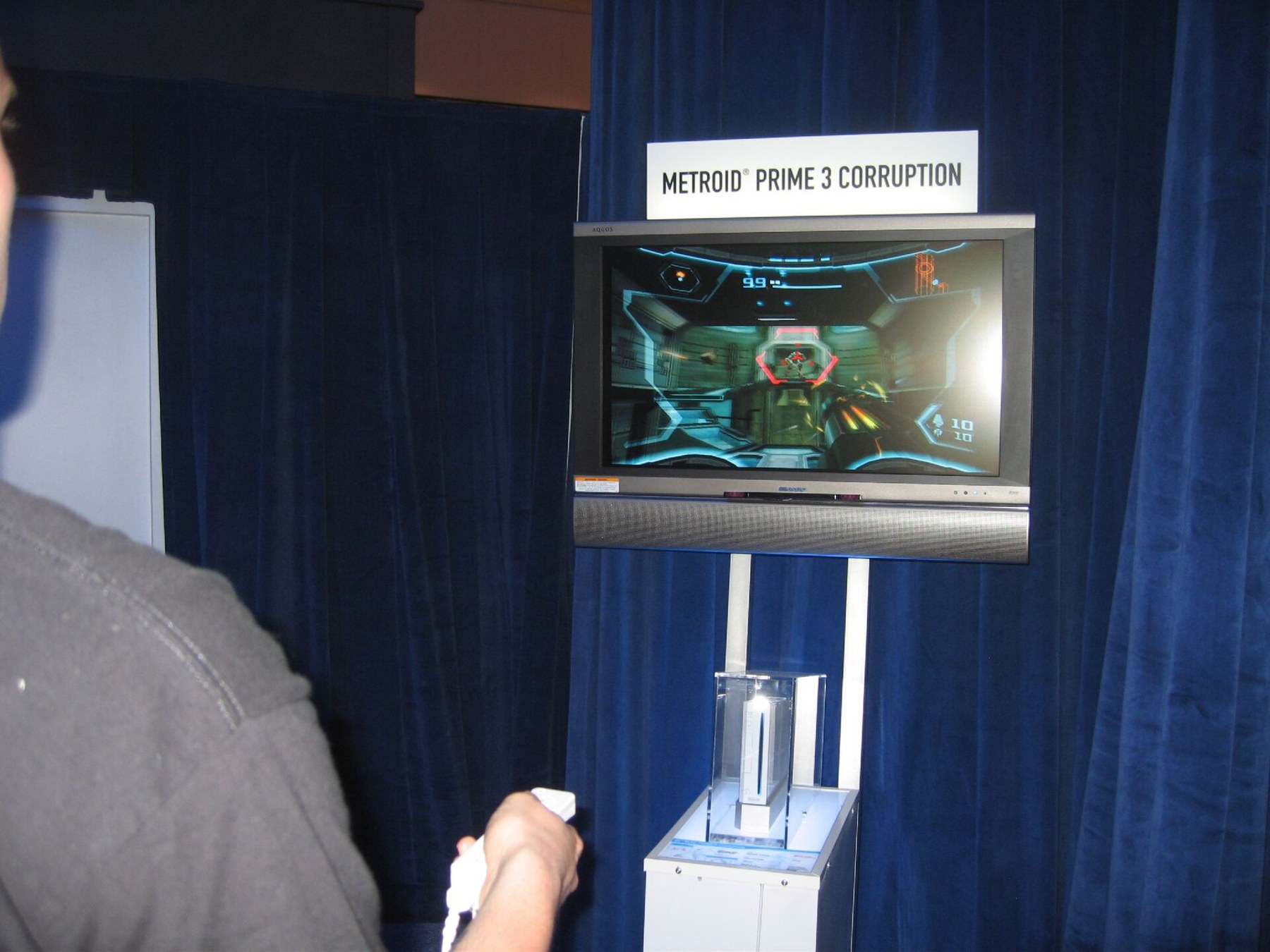
- Alex Hansen, Wii Demonstration E3 2006, Wikimedia Commons, CC BY 2.0.
Comments (0)