IR Point Tracking · Volume 6
Measuring It — An Optical Bench Procedure with the ADP3450
Seven tests that turn this dive's arithmetic into numbers: each emitter's intensity and match, the bar's steadiness, what the camera actually reports, centroid noise in screen millimetres, range and the dropout map, a survey of the room, and the 940 nm bar the PixArt camera should not see
6.1 What Is Waiting to Be Measured
Every earlier volume ends with things that could only be computed relatively or not at all. Collected:
Table 1 — Every earlier volume ends with things that could only be computed relatively or not at all. Collected
| Unknown | Raised in | Test |
|---|---|---|
| The four emitters’ relative intensities, and the beam’s fall-off to the side | Volume 2, 2.4, 2.5, 2.7 | 1 |
| Whether the bar’s light is steady from frame to frame | this volume | 2 |
| What brightness, area and box the camera reports for one emitter at each distance | Volume 1, 1.4, 1.5 | 3 |
| The camera’s real (noise-limited) resolution, in screen millimetres | Volume 1, 1.6; Volume 3, 3.8; Volume 4, 4.5 | 4 |
| The distance at which each point drops out, and the near limit when aiming at corners | Volume 4, 4.2, 4.4 | 5 |
| What each lamp, window and remote in the room puts in the passband | Volume 5, 5.2 to 5.4 | 6 |
| Whether a 940 nm bar is invisible to the PixArt camera | Volume 2, 2.2 | 7 |
The electrical bring-up, emitter currents included, is Reference Electronics, Volume 7; the R3-against-R2 comparison (its item 13) is the occasion on which tests 3 to 5 run on both cameras.
6.2 The Instruments
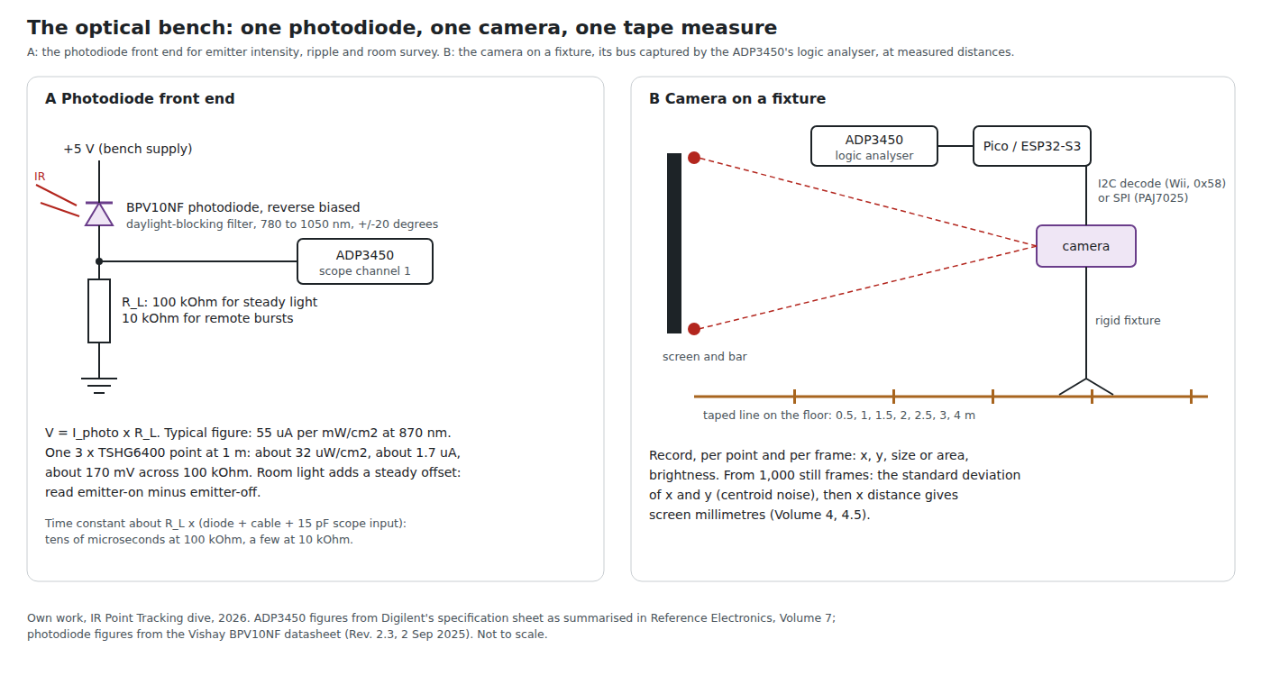
The Analog Discovery Pro ADP3450 (the bench’s main instrument, decision D9). Its specification as it bears on this build is set out in Reference Electronics, Volume 7: four 14-bit oscilloscope inputs at 1 MΩ and 15 pF, sixteen digital channels that decode I2C and SPI, two waveform generators. Here it does two jobs: a scope channel reads the photodiode, and the logic analyser decodes the camera’s bus.
A photodiode with a daylight-blocking filter, the one instrument the bench lacks. The Vishay BPV10NF is a PIN photodiode in a black T-1¾ package whose filter is “matched with 850 nm”: its sensitivity is above half its peak from 780 to 1050 nm, it peaks at 940 nm, it is specified at 55 µA for 1 mW/cm² at 870 nm with 5 V of reverse bias, its half-sensitivity angle is ±20°, and its capacitance is 11 pF at zero bias (datasheet Rev. 2.3, 2 September 2025). The filter makes it blind to most of the visible room light, and the ±20° angle lets it be pointed at one emitter at a time. Section 6.11 gives the reasons for this part over the alternatives.
The front end is the simplest possible (figure, panel A): the photodiode reverse biased from 5 V, a load resistor to ground, the ADP3450 across the resistor. The voltage is the photocurrent times the resistor. With 100 kΩ, one three-LED TSHG6400 point at 1 m (about 32 µW/cm², Volume 2, 2.4) gives about 1.7 µA and 170 mV. The time constant is the resistor times the diode, cable and scope capacitance: tens of microseconds at 100 kΩ, adequate for steady light and mains-frequency ripple; a few microseconds at 10 kΩ, needed to see a remote’s 36 to 38 kHz carrier.
A rigid fixture for the gun (panel B): a clamp or a printed cradle on a tripod, so the camera is still while 1,000 frames are recorded. Michael’s first gun, or the camera on its breakout alone, can sit in it.
A taped line on the floor at 0.5, 1, 1.5, 2, 2.5, 3 and 4 m from the screen.
6.3 Test 1: Emitter Intensity and Match
Purpose. The relative intensity of each emitter point, and of the beam to the side. Absolute radiometry would need a calibrated detector; relative numbers are what the design needs (Volume 2, 2.7).
Procedure.
- Room dark, bar powered from its own adapter. Photodiode on a stand at 0.5 m in front of one point, on the point’s axis, with a card masking the other three.
- Read the DC level on the scope, emitter on and emitter off (cover it). The difference is that point’s signal.
- Repeat for the other three points, moving the stand, not the bar.
- For one point, repeat at 15°, 30° and 45° off its axis at the same distance, horizontally and vertically.
- Repeat step 2 for one point after the bar has run for 30 minutes, to see the warm-up loss.
Reading. The four points’ signals, normalised to the brightest. The beam figures, normalised to on-axis: half at the datasheet half-angle (±27° for the TSHG6400, ±30° for the SFH 4547) confirms the part. A spread of more than about a fifth between points is worth correcting by LED selection, because the dimmest point sets the range (Volume 2, 2.7).
6.4 Test 2: Is the Bar Steady?
Purpose. The camera samples the bar for 300 µs every 4.8 ms (Volume 1, 1.7). If the bar’s light ripples at 100 or 120 Hz (a linear adapter’s ripple reaching the LEDs) or at a switching adapter’s frequency, each frame samples a different part of the ripple and the emitter’s brightness, and so its blob, varies from frame to frame. A constant-current driver should remove this (Reference Electronics, Volume 6); this test confirms it.
Procedure. The photodiode as in test 1, AC-coupled or with a math channel subtracting the mean, 100 kΩ load, timebase 5 ms per division and then 10 µs per division.
Reading. Peak-to-peak ripple as a percentage of the emitter’s signal. Under a percent or so is invisible to the tracking. Several per cent at mains frequency means the regulator has run out of headroom (a 9 V adapter sagging toward the AL5809’s minimum) or the bar is on the community’s 5.6 Ω scheme, whose current follows the supply directly (Reference Electronics, Volume 6, 6.5).
6.5 Test 3: What the Camera Reports
Purpose. The camera’s own view of one emitter: position, size or area, brightness, at each distance. This calibrates every relative figure in Volumes 2 and 4 against the sensor’s threshold.
Procedure.
- Camera on the fixture on the taped line, aimed at the screen centre.
- Logic analyser on the camera’s bus: SDA and SCL for the Wii-class camera (address 0x58), CS, SCK, MISO and MOSI for the PAJ7025. Decode with the ADP3450’s protocol analyser. Simpler, where the firmware can do it: a serial log from the gun of each frame’s objects; the OpenFIRE ESP32 port’s web app has an IR debug view that shows them (Volume 1, 1.4).
- Read the Full format (Wii class) or the extended record (PAJ7025), which carry size, box and brightness (Volume 1, 1.4 and 1.5).
- Record, for each point, at 0.5 to 4 m: the area or size, the box width and height, and the brightness fields.
Reading. Brightness and area against distance. For an emitter well below saturation the brightness should fall roughly as the inverse square; where it stops falling and the area starts shrinking, the blob is down to a few pixels and the centroid is getting coarse (Volume 1, 1.6). The ESP32 port’s source records a Wii-camera intensity range of “about 4..30, 4 at the detection limit”; the measurement shows where in that range this bar sits at each distance.
6.6 Test 4: Centroid Noise in Screen Millimetres
Purpose. The number that decides whether the R3’s coarse pixels are acceptable: how much the aim point jitters with the gun held perfectly still.
Procedure.
- Gun or camera locked in the fixture at 1, 2 and 3 m, aimed at the screen centre, room dark, bar steady (test 2 passed).
- Record 1,000 consecutive frames of each point’s x and y.
- Repeat with the room lights on, then with the sensitivity setting one step lower.
Reading. The standard deviation of x and y for each point, in the camera’s coordinate units, converted to an angle (coordinate units per degree from the field of view and the coordinate range: 1,024 over 33° for the Wii class, 4,096 over the field for the PixArt parts) and then to millimetres on the screen at that distance (Volume 4, 4.5). One 1080p pixel on a 55-inch screen is 0.63 mm. If the firmware’s own cursor output can be logged at the same time, its jitter after the homography and smoothing is the end-to-end number; the ratio of the two shows how much the four-point geometry amplifies or averages the per-point noise.
What counts as a pass is a judgement the bench result informs; a jitter well under the size of a game’s smallest target at normal distance is the practical aim. The R3-against-R2 decision (P-RE16) turns on this number more than any other.
6.7 Test 5: Range and the Dropout Map
Purpose. The far limit (Volume 4, 4.4) and the near limit when aiming at corners (Volume 4, 4.2), measured.
Procedure.
- Far limit. Fixture on the taped line, aimed at the centre. Step back 0.25 m at a time, with the IR test view open, and note the distance at which each point first flickers and then disappears. Repeat at the highest and lowest sensitivity settings.
- Near limit. At each of 0.5, 1, 1.5, 2 and 2.5 m, aim at each corner of the picture in turn and note which points the camera still holds.
- Off-screen margin. At the normal playing distance, aim progressively further beyond the left edge and note where the first point is lost (Volume 4, 4.6).
Reading. A table of distance against points held, for each camera, set beside the computed table of Volume 4, 4.2. Disagreement means either the field of view differs from the datasheet’s or the brightness limit arrives before the geometric one, and the brightness figures from test 3 at the same distances say which.
6.8 Test 6: The Room Survey
Purpose. Which sources in the room the camera will see, before they appear as fifth points (Volume 5).
Procedure.
- From the playing position, with the bar off, sweep the IR test view across the screen and its surroundings: everything that appears is an interferer. Then the same with the bar on, looking for reflections near each emitter (Volume 5, 5.5).
- With the photodiode at the playing position, pointed at the screen: read the signal with curtains open and closed, each lamp on and off, at the time of day the gun is used. Compare each with the emitter signal from test 1 at the same distance.
- With the 10 kΩ load and a fast timebase, press a button on each remote control in the room: the 36 to 38 kHz carrier bursts confirm what the camera will catch sporadically (Volume 5, 5.4).
Reading. A list of sources that appear in the IR test view, each with the photodiode’s signal as a fraction of an emitter’s. Any source whose fraction is near one, or which appears in the test view at all, is a candidate fifth point and goes on the room’s list of rules (Volume 5, 5.9).
6.9 Test 7: The Wavelength Cross-Check
Purpose. Confirm the conclusion of Volume 2, 2.2: a 940 nm bar is invisible, not merely dim, to the PixArt camera, so the stopgap bar cannot stand in for the kit bar.
Procedure. With the PAJ7025 on the fixture at 1 m, show it the SFH 4547 (940 nm) bar, then the TSHG6400 (850 nm) bar, at the highest sensitivity setting. Repeat with the Wii-class camera.
Reading. Points seen and their brightness for each combination. The expected result: the PixArt camera sees the 850 nm bar and nothing (or almost nothing) of the 940 nm bar; the Wii-class camera sees both, the 940 nm bar about twice as bright as an equal 850 nm one (WiiBrew’s figure).
6.10 The Record Sheet
One row per test condition; the columns that apply to each test.
Table 2 — 6.10 The Record Sheet
| Date | Test | Camera | Bar | Distance, m | Angle | Point | Photodiode, mV (on minus off) | Area or size | Brightness | σx, σy (units) | Jitter, mm | Points held | Notes |
|---|---|---|---|---|---|---|---|---|---|---|---|---|---|
6.11 Why This, and Why Not the Others
The bench needs one new part, an infrared detector. The criteria: responds at both 850 and 940 nm (both bars are in use); blind to most visible light (so a lit room does not swamp it); narrow enough in angle to single out one emitter at half a metre; cheap and stocked.
Pick: Vishay BPV10NF. Its daylight-blocking filter is “matched with 850 nm” and its half-sensitivity band runs from 780 to 1050 nm, so it sees both bars; its ±20° acceptance picks out one emitter; it is a two-lead part that sits on a stand with a resistor; LCSC listed it at $0.6549 on 2026-10-19.
Table 3 — 6.11 Why This, and Why Not the Others
| Rejected | Why |
|---|---|
| Vishay BPW41N | The same 7.5 mm² chip as the BPW34 behind a filter “matched with 940 nm”; its half-sensitivity band starts at 870 nm, so it barely sees the 850 nm kit bar |
| Vishay BPW34 | No filter: sensitive from 430 nm, so visible room light dominates its signal; ±65° acceptance takes in all four emitters and the room. A spare for a dark room only |
| A phone camera | Shows that an emitter is lit, which is useful, but gives no number; many phone cameras carry an infrared-cut filter |
| The gun’s own camera alone | The true in-band instrument, and tests 3 to 7 use it; but its readings pass through the threshold, gain and saturation that are being characterised, so an independent detector is needed for the emitters and the room |
| A calibrated optical power meter | Gives absolute irradiance; not needed, because every decision here rests on relative figures |
6.12 Where to Buy
Table 4 — 6.12 Where to Buy
| Item | Seller | Price, 2026-10-19 | Notes |
|---|---|---|---|
| Vishay BPV10NF | LCSC C118288 | $0.6549 (1+), $0.5286 (10+) | 2,508 in stock on the day |
| Vishay BPW34 (spare) | LCSC C85128 | $1.0647 (1+), $0.9466 (10+) | 22,894 in stock on the day |
| Vishay BPW34 (spare) | SparkFun PRT-09541 | $1.75 | sold as “Miniature Solar Cell”; the bare photodiode |
| Analog Discovery Pro ADP3450 | on the bench | decision D9 | |
| Emitter LEDs for both bars | see Reference Electronics, Volume 6, 6.9 |
DigiKey refused automated reading on the day and Mouser timed out, so no price from either is recorded.
6.13 What Could Not Be Verified
- Whether the ADP3450’s protocol analyser keeps up with a continuous capture of the camera bus for 1,000 frames in its buffer; at 209 frames a second that is under five seconds of traffic, which its 32 M-sample buffers should hold, but it has not been tried.
- Whether the OpenFIRE App (v6.2 firmware) can log raw camera points to a file; the ESP32 port’s web app shows them, and a fork can print them over serial.
- The BPV10NF’s response at 850 nm specifically; the datasheet gives 55 µA at 870 nm and a band from 780 to 1050 nm, and the two bars are compared with each other, so it does not matter for test 1.
Sources
- Vishay Semiconductors, BPV10NF Silicon PIN Photodiode, Rev. 2.3, 2 September 2025, document 81503, https://www.vishay.com/docs/81503/bpv10nf.pdf; BPW41N, Rev. 1.6, 23 August 2011, document 81522; BPW34, Rev. 2.1, 23 August 2011, document 81521. Read 2026-10-19.
- Digilent, Analog Discovery Pro ADP3450/ADP3250 Specifications, rev 0924, as summarised in Reference Electronics, Volume 7.
- LCSC product pages C118288 and C85128, and SparkFun PRT-09541, read 2026-10-19.
- WiiBrew wiki, Wiimote, “IR Camera” (940 against 850 nm), https://wiibrew.org/wiki/Wiimote.
- Alessandro Satanassi, OpenFIRE-Firmware-ESP32,
lightgun/src/OpenFIRECamera.cpp(IR debug, intensity range), read 2026-10-19. - Vishay Semiconductors, Data Formats for IR Remote Control, document 80071, Rev. 2.3 (remote carrier frequencies).
Comments (0)