IR Point Tracking · Volume 2
The Emitters — Wavelength, Radiant Intensity and the Link Budget
Why the camera's filter, not preference, picks 850 or 940 nm; what sunlight and a tungsten lamp put in each band; how many milliwatts per steradian reach the gun at 1 to 5 m; why a point is a cluster of LEDs that must stay one blob; and why the wide-angle PixArt R3 collects a thirty-ninth of the R2's light
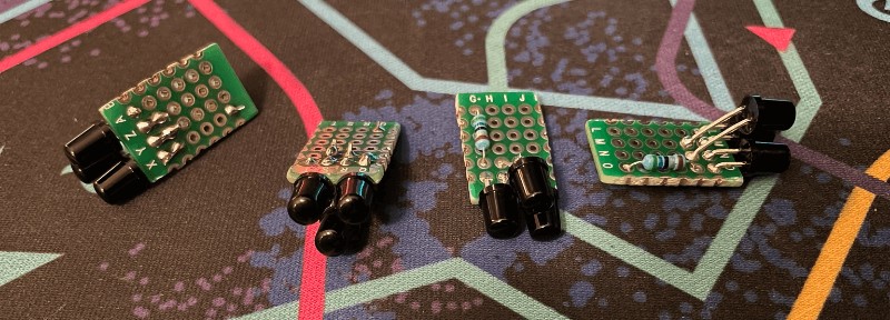

2.1 What an Emitter Has to Do
An emitter’s job is to be the brightest thing in the camera’s passband, by a clear margin, at every position the player will take, while looking to the camera like a single small point. Each part of that sentence is a design parameter:
- In the passband. Light outside the camera’s filter does not exist as far as the sensor is concerned (2.2).
- Brightest, by a margin. The sensor has a threshold and nothing else (Volume 1). Every other source in the passband, sunlight, a lamp, a reflection, competes on the same terms (2.3, and Volume 5).
- At every position. Intensity falls with the square of distance (2.4) and with the angle off the LED’s axis (2.5), and the camera’s own optics lose light toward the edge of the field (Volume 4).
- A single small point. Several LEDs make one point, and must merge into one blob at every distance (2.6).
The hardware that meets these requirements, the LED part, its current regulator and the bar’s mechanics, is designed in Reference Electronics, Volume 6. This volume supplies the physics those choices rest on.
2.2 The Filter Chooses the Wavelength
Silicon responds across the whole near infrared, so the sensor itself is not what limits the wavelength. The filter in front of it is.
The Wii class prefers 940 nm. WiiBrew, from measurement: “With the IR-pass filter intact, 940nm sources are detected with approximately twice the intensity of equivalent 850nm sources, but are not resolved as well at close distances.” The camera library OpenFIRE uses gives the same advice, citing WiiBrew. The filter’s passband has never been published; WiiBrew describes the camera’s internal filter as “dichroic-coated glass … (of unknown optical properties)”.
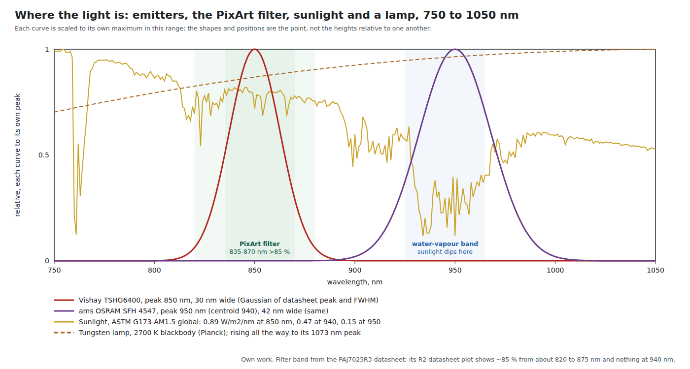
The PixArt PAJ7025 is an 850 nm sensor, and 940 nm is not merely weaker but blocked. The R2 datasheet’s key parameters give a “Target object tracking wavelength” of 850 nm, and its features list “Suitable wavelength of tracking target: infrared ray 850 nm LED”. Its filter transmittance plot (Figure 4) shows about 85 % transmission from roughly 820 to 875 nm and essentially zero beyond about 890 nm. The R3 datasheet states the band numerically: over 85 % from 835 to 870 nm, over 90 % from 840 to 850 nm, and under 3 % average from 400 to 780 nm, with nothing said about 940 nm. The plot settles what the R3’s table leaves open. An SFH 4547, whose output is centred on 940 nm with half its power between about 920 and 960 nm, puts almost nothing into that passband.
Reference Electronics, Volume 6 already concludes that a kit bar for the PixArt camera is an 850 nm bar, on the strength of the R3’s table and the ESP32 port’s README. The R2 plot makes the conclusion stronger: a 940 nm bar is not a dim bar for the PixArt camera but an invisible one, and a bar built for the Wii-camera stopgap cannot be used to test the kit camera.
Matching the emitter’s width to the filter. The Vishay TSHG6400 (850 nm peak, 30 nm spectral bandwidth, temperature coefficient 0.28 nm/K, datasheet Rev 1.5) sits wholly inside the PixArt passband. Its peak drifts 0.28 nm per kelvin, so a 40 K rise in junction temperature moves it about 11 nm, still inside. A broad or off-centre 850 nm part would lose the half of its output that falls on the filter’s edges.
2.3 850 or 940 nm in a Real Room
The question “which wavelength is better” has a different answer for each interfering source, and the figure shows why.
Sunlight. Integrating the ASTM G173 reference spectrum (sea level, sun 48° from the zenith) over each band:
Table 1 — Sunlight. Integrating the ASTM G173 reference spectrum (sea level, sun 48° from the zenith) over each band
| Band | What it represents | Sunlight in the band, global | Direct beam only |
|---|---|---|---|
| 835 to 870 nm | PixArt filter, over 85 % | 34.1 W/m² | 31.6 W/m² |
| 919 to 961 nm | the SFH 4547’s half-power width | 17.7 W/m² | 16.7 W/m² |
| 380 to 780 nm | visible, for scale | 534 W/m² | 468 W/m² |
At 940 nm the sun is in a water-vapour absorption band, and the reference spectrum puts 0.47 W/m² per nanometre there against 0.89 at 850 nm. At the SFH 4547’s 950 nm peak it is 0.15. So a 940 nm system meets about half the sunlight of an 850 nm system in a band of the same width. The figure depends on how much water is in the air (the reference assumes a fixed amount) and indoors on the glazing, since many modern window coatings reflect part of the near infrared; the direction holds.
Tungsten and halogen lamps. A filament is a blackbody near 2700 to 3000 K, peaking around 1000 nm, so it puts slightly more into the 940 nm band than into the 850 nm band. Planck’s law gives the fraction of a 2700 K lamp’s radiated power in each band as 1.9 % (835 to 870 nm) and 2.5 % (919 to 961 nm). A 60 W incandescent bulb, if about 90 % of its input leaves as radiation, then radiates about 1.0 W into the PixArt band and 1.3 W into the 940 nm band: on the order of 80 to 110 mW per steradian if spread evenly, which is the same order as an emitter point (2.4). A bare filament in view is a competing point source, at either wavelength. LED and fluorescent lamps, by contrast, emit very little in the near infrared, so a room lit by them is benign.
The visible glow. An 850 nm LED shows a faint red glow to most eyes; a 940 nm one is essentially invisible. That is a reason to prefer 940 nm where the camera allows (Reference Electronics, Volume 6), and for a PixArt camera the camera does not allow it.
The result. The wavelength is the camera’s decision. With the Wii-class stopgap, 940 nm also halves the sunlight. With the PixArt kit camera, 850 nm is the only choice, and the extra sunlight is one more reason the R3 needs the ambient-light care of Volume 5.
2.4 Radiant Intensity and the Inverse Square
Emitter datasheets give radiant intensity in milliwatts per steradian, measured on the LED’s axis (the SFH 4547’s is measured “at a solid angle of Ω = 0.01 sr”). A small source at distance d produces an irradiance at the camera of I / d², and the camera collects that irradiance over its entrance pupil (2.8). For one emitter point of three LEDs at 100 mA, using the datasheets’ typical figures:
Table 2 — Emitter datasheets give radiant intensity in milliwatts per steradian, measured on the LED's axis (the SFH 4547's is measured "at a solid angle of Ω = 0.01 sr"). A small source at distance d produces an irradiance at the camera of I / d², and the camera collects that irradiance over its entrance pupil (2.8). For one emitter point of three LEDs at 100 mA, using the datasheets' typical figures
| Emitter point | Intensity | 1 m | 2 m | 3 m | 4 m | 5 m |
|---|---|---|---|---|---|---|
| 3 × SFH 4547, typical 50 mW/sr each (940 nm) | 150 mW/sr | 150 | 37.5 | 16.7 | 9.4 | 6.0 |
| 3 × SFH 4547, lowest bin, 28 mW/sr each | 84 mW/sr | 84 | 21.0 | 9.3 | 5.2 | 3.4 |
| 3 × TSHG6400, typical 105 mW/sr each (850 nm) | 315 mW/sr | 315 | 78.8 | 35.0 | 19.7 | 12.6 |
Irradiance at the gun, in mW/m², on the LED’s axis. Arithmetic from the datasheet figures; the three-per-point arrangement is the community one (PICON-AS parts list, Reference Electronics, Volume 6).
Three things to take from the table:
- Distance is expensive. Going from 2 m to 4 m costs a factor of four. A typical SFH 4547 point at 5 m delivers less than a lowest-bin point at 3 m.
- The bin matters as much as the part. The SFH 4547’s bins span 28 to 112 mW/sr; a bar built from the lowest bin reaches only as far as a typical bar would at three-quarters of the distance.
- Temperature costs a little. The SFH 4547 loses about 0.5 % of its output per kelvin; a bar that warms 30 K loses about 15 %.
None of these numbers says whether the camera sees the point, because the sensor’s detection threshold in absolute units is published for neither camera. The table is for comparisons: between parts, distances, bins and wavelengths. The absolute range is a bench measurement (Volume 6).
2.5 Beam Angle and Where the Player Sits
An LED’s half angle is the angle off its axis at which its intensity has fallen to half. The SFH 4547’s is ±30°, the TSHG6400’s ±27°. A player who stands 30° off an emitter’s axis gets half the intensity the table shows, and beyond that it falls faster.
Close to a large screen the angles grow quickly. For a gun on the screen’s centreline, the angle from a square-layout emitter’s axis (emitters at 20 and 80 % of the width, on the top and bottom edges, facing straight out) to the gun is:
Table 3 — Close to a large screen the angles grow quickly. For a gun on the screen's centreline, the angle from a square-layout emitter's axis (emitters at 20 and 80 % of the width, on the top and bottom edges, facing straight out) to the gun is
| Screen | Distance | Angle off the emitter’s axis |
|---|---|---|
| 55 in | 2.5 m | 11° |
| 55 in | 1.5 m | 18° |
| 55 in | 0.8 m | 32° |
| 65 in | 1.0 m | 31° |
So the close range that the PixArt R3’s wide lens makes possible (about 0.8 m from a 55-inch screen, Reference Electronics, Volume 3) also puts the gun at the edge of a ±30° beam, and a player who also moves sideways is outside it. Two remedies exist, and Nintendo used one of them. The Wii Sensor Bar’s LEDs are not all parallel: per WiiBrew, “The LEDs furthest from the center are pointed slightly outwards, the LEDs closest to the center are pointed slightly inwards, while the rest are pointed straight forward.” Fanning the LEDs of one point widens its combined beam at the cost of on-axis intensity. The other remedy is to aim each point at the usual playing position (Reference Electronics, Volume 6, 6.8). Choosing a narrower, brighter LED does the opposite of what close play needs; that is why the SFH 4550’s 6° beam was rejected there.
2.6 A Point Is a Cluster, and Must Stay One Blob
One LED is rarely bright enough, so each point is built from several: three in the community bars, five in each end of the Wii Sensor Bar. The camera does not know that. It sees whatever pixels are lit, and groups touching ones into objects (Volume 1). A cluster is one point only if its LEDs’ images merge.
The test is the LED pitch against the size of one pixel, projected out to the emitter. The distance one pixel spans at the emitter is the distance times the pixel’s angular size:
Table 4 — The test is the LED pitch against the size of one pixel, projected out to the emitter. The distance one pixel spans at the emitter is the distance times the pixel's angular size
| Camera | One pixel spans, at 0.8 m | 1.5 m | 2.5 m | 4 m |
|---|---|---|---|---|
| Wii class (33° over 128 pixels) | 3.6 mm | 6.7 mm | 11.2 mm | 18.0 mm |
| PixArt PAJ7025R2 (11 µm pixel, 1.484 mm focal length) | 5.9 mm | 11.1 mm | 18.5 mm | 29.6 mm |
| PixArt PAJ7025R3, centre of field (0.378 mm focal length) | 23.3 mm | 43.7 mm | 72.8 mm | 116 mm |
Arithmetic from WiiBrew’s field of view and the PixArt datasheets’ focal lengths.
Read with care, the table gives a rule. When the LED pitch is smaller than one pixel span, adjacent LEDs fall on the same or touching pixels and the cluster is one blob, whatever the gap between the LEDs. When the pitch is several pixel spans, the cluster can break into separate objects, each taking a slot. 5 mm LEDs mounted touching have a pitch of about 5 mm, which is safe at every distance in the table except the Wii camera at under a metre. A cluster spread out along a strip, or LEDs placed a centimetre apart for cooling, is not safe for the Wii camera at ordinary distances: at 1.5 m a 15 mm pitch is more than two Wii pixels. Lens blur widens each image and helps the merge, so the table is the worst case.
This is also the likeliest reading of WiiBrew’s remark that 940 nm sources “are not resolved as well at close distances”. The Wii Sensor Bar’s five LEDs per end span roughly 2 cm (judged from the photograph above), which is several Wii pixels at close range. Whether the camera’s response at 940 nm or the cluster geometry is behind the remark is not stated.
The rule for a bar: mount each point’s LEDs touching, in a tight group rather than a line, so the group spans as little as possible. The PixArt R3’s large pixels make this easy; the Wii-class stopgap is the camera to check it with.
2.7 Matching the Four Points
The four points need not be equally bright to be tracked, but mismatch has costs:
- Detection range is set by the dimmest point, which is the first to fall below threshold as the player steps back.
- Centroid quality depends on how many pixels clear the threshold (Volume 1, 1.6), so a dim point is located more coarsely than a bright one.
- Rejection rules that use the brightness or size fields of the richer reports (the Wii Full format, the PAJ7025 extended record) to tell an emitter from a reflection need the four emitters to look alike.
The SFH 4547’s bins span a factor of four (28 to 112 mW/sr), so LEDs from mixed bins can give a factor-of-four spread between points, before any difference in current. A constant-current driver per point removes the current term (Reference Electronics, Volume 6, 6.6); buying all the LEDs for a bar from one packing unit removes most of the bin term (“Only one group in one packing unit”, SFH 4547 datasheet). The PAJ7025’s per-object brightness figures make the match measurable from the gun itself (Volume 6).
2.8 The Camera’s Side of the Link: Light Grasp
The emitter is half the link; the camera’s lens is the other half. The power a camera collects from a point source is the irradiance times the area of its entrance pupil, and the pupil’s diameter is the focal length divided by the f-number. The two PixArt datasheets give both:
Table 5 — The emitter is half the link; the camera's lens is the other half. The power a camera collects from a point source is the irradiance times the area of its entrance pupil, and the pupil's diameter is the focal length divided by the f-number. The two PixArt datasheets give both
| PAJ7025R2 | PAJ7025R3 | |
|---|---|---|
| Effective focal length | 1.484 mm | 0.378 mm |
| f-number | 1.838 | 2.93 |
| Entrance pupil diameter (focal length ÷ f-number) | 0.81 mm | 0.13 mm |
| Field of view, horizontal and vertical | 38.3° | 113° |
| Relative illumination at the edge of the field | over 60 % | 38.5 % |
| Distortion | under 2.8 % | −30 % |
The pupil’s area ratio is (0.13 ÷ 0.81)², about 1/39. From the same emitter at the same distance, the R3 collects about one thirty-ninth of the light that the R2 collects, and at the edge of its field 38.5 % of that again. To deliver the same signal it must be about 6.3 times closer (the square root of 39), or the emitter 39 times brighter, or the gain correspondingly higher. That is consistent in direction with PixArt’s own product pages, which give the R2 a range of “up to 7 meters” and the R3 a working distance of 3 m, and with the OpenFIRE ESP32 port’s R3 presets, which all run at 4 to 8 times gain (Volume 1, 1.8).
There is a second, less obvious cost. Background light from an extended surface, a wall or a window, fills each pixel, and the power per pixel from such a surface depends on the f-number alone, not the focal length. The R3’s slower f-number gives it (1.838 ÷ 2.93)², about 0.39, of the R2’s background per pixel. So the R3’s ratio of emitter to background is 1/39 ÷ 0.39, about one fifteenth of the R2’s. (That is simply the square of the focal-length ratio: a short focal length spreads each pixel over a large patch of wall.) Volume 5 turns this into per-pixel numbers for a sunlit wall.
This is not an argument against the R3; Reference Electronics, Volume 3 chose it because it is the only buyable part whose field of view suits a large television at living-room distance. It is a requirement on the emitters that come with it: an R3 kit’s bar has to be considerably brighter than a Wii-camera bar, it has to be 850 nm, and the room has to be kinder. Those requirements belong in the bench comparison of R3 against R2 that decision P-RE16 already calls for.
2.9 Steady, Pulsed or Synchronised
Every published DIY bar drives its LEDs with steady current, and Reference Electronics, Volume 6 explains why: pulsing helps only if the pulses coincide with the camera’s exposure, and OpenFIRE has no way to tell the bar when that is. Volume 1 (1.7) adds the numbers that make synchronisation attractive. The OpenFIRE ESP32 port exposes for 300 µs of each 4.8 ms frame, a duty of about 6 %; the SFH 4547 may be driven at 1 A for up to 400 µs at a duty of 0.5 % or less, against 100 mA continuous.
The two ratings do not line up: at 209 frames a second, a 300 µs pulse is a 6 % duty, twelve times the SFH 4547’s pulsed duty limit. A synchronised bar would therefore run at an intermediate current that keeps the LED within its average dissipation, or pulse only on alternate frames, or use an LED rated for higher-duty pulsing. A factor of four over the steady current is worth exactly as much as halving the distance. Frame subtraction (Volume 1, 1.9) would add rejection of everything steady on top. Both need a timing link from the gun to the bar; they are research for the Experimental Sensing dive.
2.10 Why This, and Why Not the Others
This dive does not choose the bar’s parts; Reference Electronics, Volume 6 does. What it adds is the sensing requirement each choice must meet, and whether the current picks meet it.
Table 6 — 2.10 Why This, and Why Not the Others
| Requirement | From | Current pick (Reference Electronics) | Meets it? |
|---|---|---|---|
| Wavelength inside the camera’s passband | 2.2 | 850 nm TSHG6400 for the PixArt kit camera; 940 nm SFH 4547 for the Wii-camera stopgap | Yes, if the bars are never swapped between cameras. A 940 nm bar is invisible to a PixArt camera, so the stopgap bar cannot test the kit camera |
| Emitter narrower than the passband | 2.2 | TSHG6400, 30 nm wide, 850 nm peak | Yes; the peak stays inside the 835 to 870 nm band for any plausible temperature rise |
| Beam wide enough for the playing area | 2.5 | ±27° to ±30° parts; narrow SFH 4550 rejected | Yes at 1.5 m and beyond; marginal at the R3’s closest distances, where fanning each point’s LEDs is the remedy |
| Each point one blob | 2.6 | three LEDs per point | Yes if mounted touching; specify that in the mechanical design |
| Points matched | 2.7 | AL5809 constant current per point | Yes for current; buy LEDs from one packing unit for the bin |
| Enough intensity for the camera’s light grasp | 2.8 | 100 mA steady, three LEDs per point | Not established for the R3; the R2 against R3 bench comparison must measure range with the kit bar |
Rejected as sensing approaches, not as parts: a 940 nm bar for the PixArt camera (outside its filter, 2.2); a single LED per point (not enough intensity for a television at living-room distance with the R3, 2.4 and 2.8); LEDs spread out along a strip for each point (splits into several blobs for the Wii-class camera, 2.6).
2.11 What Could Not Be Verified
- The absolute detection threshold of either camera in irradiance units, and hence any absolute range. Only comparisons are made here.
- The Wii camera’s filter passband, and the reason WiiBrew’s 940 nm sources are “not resolved as well at close distances”.
- The PAJ7025R3’s transmission at 940 nm (its datasheet is silent; the R2’s plot shows none, and the two modules may not share a filter).
- The Wii Sensor Bar’s LED pitch and cluster span, which are estimated here from a photograph.
- How much near infrared a given window passes; it varies with the glazing.
Sources
- WiiBrew wiki, Wiimote, “IR Camera: Optical Characteristics”, https://wiibrew.org/wiki/Wiimote, and Sensor Bar, https://wiibrew.org/wiki/Sensor_Bar, wikitext read 2026-10-19.
- PixArt Imaging, PAJ7025R2 Product Datasheet v1.3 (21 Nov 2019), key parameters, Table 6 optical specifications and Figure 4 filter response; and PAJ7025R3 Product Datasheet v1.0 (16 Dec 2016), optics and filter, as tabulated in Reference Electronics, Volume 3. Both “PixArt Confidential”, read from partial copies in alextrical/PAJ7025-KiCad-Library on GitHub; not stored.
- PixArt Imaging, PAJ7025R2 and PAJ7025R3 product pages (range “up to 7 meters”, working distance 3 m), as read for Reference Electronics on 2026-10-18.
- ams OSRAM, SFH 4547 datasheet v1.7 (2022-08-08); Vishay, TSHG6400 datasheet Rev 1.5 (17 Mar 2025), https://www.vishay.com/docs/84636/tshg6400.pdf, read 2026-10-19.
- ASTM G173-03 reference solar spectral irradiance (AM1.5), the copy distributed with pvlib-python (
pvlib/data/ASTMG173.csv), integrated here; the arithmetic is in the dive’s04-templates/calc_radiometry.py. - Planck’s law, evaluated for 2700 K and 3000 K in the same script.
- Alessandro Satanassi, OpenFIRE-Firmware-ESP32,
lightgun/src/OpenFIRECamera.cpp(R3 gain presets), read 2026-10-19. - retrohandhelds.gg, A brief look at the GUN4IR light gun (2022), emitter photograph.
Comments (0)