IR Point Tracking · Volume 3
Geometry — How Many Points, and Where to Put Them
Each point fixes two numbers: two points give aim, roll and distance; four give a full perspective map of a flat screen. A simulation of the error each leaves, the Wii bar, GunCon 3 markers, square and diamond layouts read as geometry, and the layout proposed for this build
3.1 The Question the Points Answer
A light gun is supposed to report where the barrel points on the screen: the place where a line along the barrel meets the plane of the picture. The camera is fixed to the barrel, so that line is (after calibration) the camera’s optical axis, which lands on the centre of the camera’s image. The question the emitter points answer is therefore: which point on the screen is imaged at the centre of the camera’s sensor?
To answer it the firmware needs the mapping from camera-image coordinates to screen coordinates. It knows where the emitters are on the screen (from the layout and from calibration) and it measures where they are in the image (from the sensor’s report, Volume 1). Each emitter seen gives one correspondence between the two. How many correspondences are needed depends on how general a mapping must be allowed for, and that is the subject of this volume. How the mapping is computed, conditioned and calibrated in detail belongs to Aiming Maths and Calibration; how OpenFIRE does it in practice, to Open-Source Firmware, Volume 2.
3.2 Counting: Two Numbers per Point
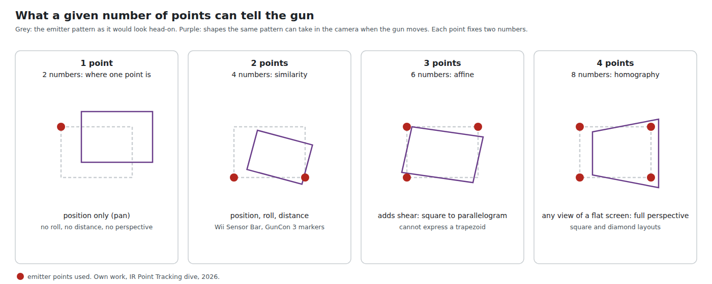
Each point in the image gives two numbers, its x and y. A mapping with n free parameters needs at least n/2 points:
Table 1 — Each point in the image gives two numbers, its x and y. A mapping with n free parameters needs at least n/2 points
| Points | Numbers | Mapping it can determine | Free parameters | What it captures |
|---|---|---|---|---|
| 1 | 2 | translation | 2 | where the pattern is in the image |
| 2 | 4 | similarity | 4 | position, roll (the angle of the line between the points) and scale (their separation, which gives distance) |
| 3 | 6 | affine | 6 | adds shear and unequal stretch: a rectangle seen as a parallelogram |
| 4 | 8 | homography (projective) | 8 | any view of a flat plane by a pinhole camera: a rectangle seen as a general quadrilateral |
The last row is the important one. A flat screen seen by a camera from an arbitrary position and angle is related to its head-on appearance by a homography, a 3 × 3 matrix defined up to scale, so eight unknowns. Four points, no three of them in a line, determine it exactly; fewer cannot. That is the whole reason the open firmware uses four emitters.
3.3 Two Points: the Wii and the GunCon 3
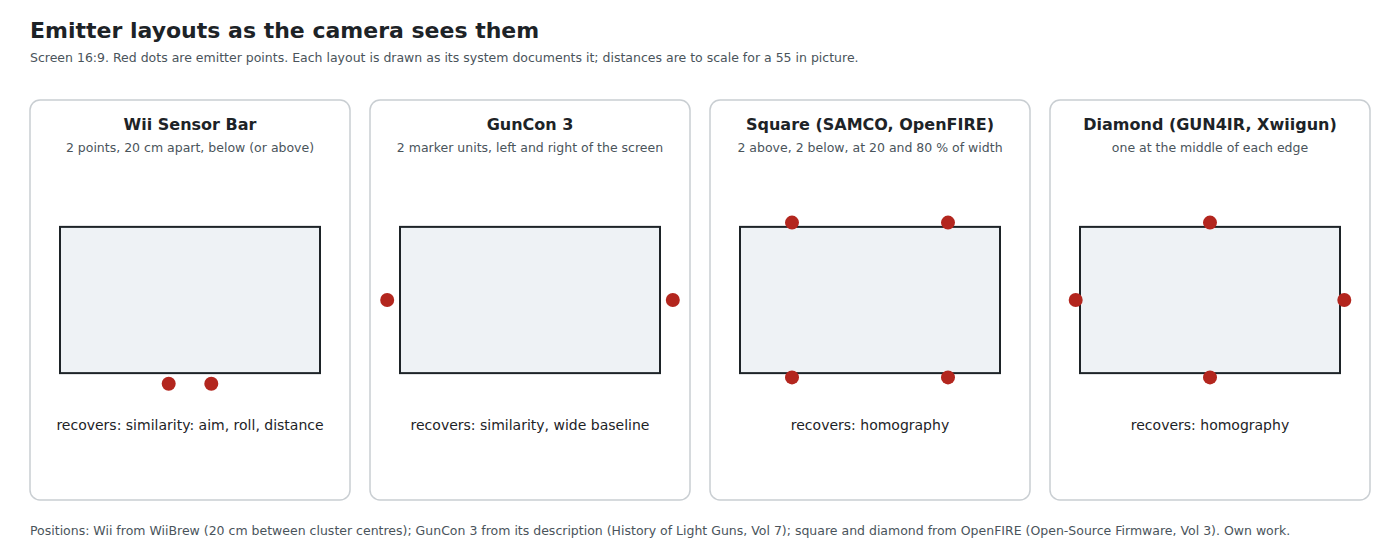
The Wii Sensor Bar provides two points, 20 cm apart (WiiBrew, “as measured on one unit”), and the GunCon 3 two marker units at the left and right of the screen (History of Light Guns, Volume 7). Two points give a similarity: where the pair is in the image (the aim), the angle of the line joining them (the roll of the controller) and their separation (inversely, the distance to the bar). History of Light Guns, Volume 7 describes this as the Wii Remote’s method.
What a similarity cannot represent is perspective. It treats the camera as if it always looked squarely at the plane of the emitters. That is exactly true only when the camera’s axis is perpendicular to the screen. As soon as the gun is aimed at a corner, or the player stands to one side, the true mapping is a homography and the similarity is an approximation of it. For a pointer on a menu that is perfectly acceptable, because the user steers the cursor by watching it. For a gun, where the player aims down the barrel or the sights and expects the shot to land where the barrel points, the error is visible.
A two-point system has a second problem that a four-point one does not: depth. The separation of the two points depends on distance and on the angle from which the bar is seen (it shrinks as the cosine of the angle), so a player who moves sideways appears to have stepped back.
3.4 Four Points: Perspective
With four points at known positions on the screen plane, the homography is determined exactly at every frame, whatever the player’s position, height, distance or roll. Pushing the image centre through it gives the aim point directly. Johnny Lee’s Wiimote whiteboard code computed it this way, and OpenFIRE’s OpenFIRE_Perspective::warp() is a credited port of it (Open-Source Firmware, Volume 2).
Three requirements fall on the emitters, and they are the sensing side’s contribution:
- No three in a line. Three collinear points carry only the information of two along that line; the homography becomes undetermined. Both the square and the diamond layouts avoid this by construction. A design that put all four emitters on one bar would not.
- Known positions, in a plane. The homography maps one plane to another. Emitters meant to sit on the screen’s plane but mounted on a bar standing proud of it by a few centimetres introduce a small parallax error that grows with the angle of view. The firmware’s calibration absorbs a fixed error, not one that changes as the player moves.
- A rigid pattern. The mapping is computed afresh every frame from the four positions. A bar that sags, or a point whose LEDs flicker between merged and split (Volume 2, 2.6), moves the computed aim point although the gun has not moved.
3.5 A Simulation of the Model Error
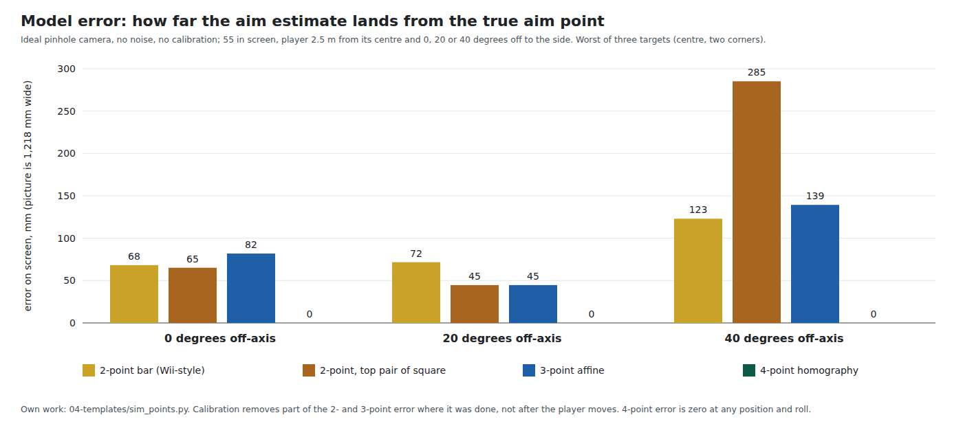
To put sizes on the difference, a small simulation (the dive’s 04-templates/sim_points.py) places an ideal pinhole camera in front of a 55-inch picture (1,218 by 685 mm), aims it at a target, projects the emitters into its image, and asks each method where it thinks the camera is aimed. There is no sensor noise and no lens distortion, so the result isolates the error of the model alone. Two-point uses either a Wii-style bar 20 cm wide, 3 cm below the picture, or the top pair of a square layout; three-point uses three of the square’s emitters; four-point uses all four.
Table 2 — 3.5 A Simulation of the Model Error
| Player position | Target | Two points, Wii-style bar | Two points, top pair of square | Three points, affine | Four points, homography |
|---|---|---|---|---|---|
| head-on, 2.5 m | centre | 0 | 0 | 0 | 0 |
| head-on | top-left corner | 68 | 21 | 21 | 0 |
| head-on | bottom-right corner | 32 | 65 | 82 | 0 |
| 20° to the side | centre | 32 | 42 | 25 | 0 |
| 20° to the side | top-left corner | 72 | 45 | 45 | 0 |
| 20° to the side | bottom-right corner | 15 | 34 | 42 | 0 |
| 40° to the side | centre | 123 | 127 | 47 | 0 |
| 40° to the side | top-left corner | 39 | 60 | 60 | 0 |
| 40° to the side | bottom-right corner | 72 | 285 | 139 | 0 |
Error on the screen in millimetres between the estimated and the true aim point. A 1080p pixel on this screen is 0.63 mm, so 68 mm is about 107 pixels and 285 mm about 450.
The four-point estimate is exact everywhere, and stays exact with the camera rolled 15° as well (the script checks this). The others are wrong by several centimetres even head-on, because aiming at a corner tilts the camera relative to the screen, which is itself a perspective view. A real two-point system calibrates, which removes much of the head-on error at the place calibration was done; what calibration cannot remove is the change in error when the player moves, and the table shows that change running from a few centimetres to over twenty.
3.6 Layouts Read as Geometry
The firmware projects define their layouts (Open-Source Firmware, Volume 3 quotes OpenFIRE’s: square, two emitters above and two below the picture at 20 and 80 % of its width; diamond, one at the middle of each edge). Read as sensing geometry, four properties separate them.
Baseline. The further apart the points, the more pixels lie between them, and the less a given centroid error tilts the computed mapping. On a 55-inch screen the square layout’s top pair is 0.73 m apart and the Wii bar’s points 0.20 m. Seen from a distance, the square’s top pair subtends:
Table 3 — Baseline. The further apart the points, the more pixels lie between them, and the less a given centroid error tilts the computed mapping. On a 55-inch screen the square layout's top pair is 0.73 m apart and the Wii bar's points 0.20 m. Seen from a distance, the square's top pair subtends
| Distance | Angle | Wii-class pixels | PAJ7025R2 pixels | PAJ7025R3 pixels |
|---|---|---|---|---|
| 1 m | 40.1° | 156 | 103 | 35 |
| 2 m | 20.7° | 80 | 53 | 18 |
| 3 m | 13.9° | 54 | 36 | 12 |
| 4 m | 10.4° | 40 | 27 | 9 |
| 5 m | 8.4° | 32 | 21 | 7 |
Arithmetic from the fields of view (WiiBrew; PixArt datasheets; the R3 figure is an average over its distorted field). At 4 m the R3 has nine pixels between two emitters; everything the homography knows about perspective lives in small differences between those nine-pixel spans. That is one more reason the R3 suits close play and the R2 or Wii-class camera longer distances (Volume 4).
Which points leave the field first. Aiming at a corner pushes the opposite emitters toward the edge of the camera’s view. The square layout’s emitters sit 20 % in from each side, so at most 80 % of the screen’s width must fit in the camera’s half-field; the diamond’s side emitters sit at the very edges, so the full width must. Volume 4 turns this into distances.
Symmetry and identity. The camera reports points, not names; the firmware must decide which is top-left (Volume 1, 1.4). The square and the diamond are both symmetric under a half turn, so the camera alone cannot tell a gun held upside down from one held normally. A sort that assigns points to quadrants around their median works while the roll stays within ±45°; beyond that the quadrants exchange and the decoded picture turns over. For a light gun that is never an issue in play, but it is the reason a held-sideways gun “jumps”, and it is a limit no tuning removes. The Wii Remote has motion sensors that can resolve the ambiguity; a light gun without an IMU cannot.
Mounting. The square layout needs emitters only above and below the picture, two bars on the bezel. The diamond needs emitters on the left and right edges at mid-height as well, which on a wall-mounted or very thin television is the awkward place to fix anything.
3.7 When a Point Goes Missing
Points leave the field of view when the gun aims near a corner from close range, and are blocked by a hand or a player. With three points visible the homography is underdetermined, and the firmware has a choice: stop, fall back to an affine estimate from three, or rebuild the fourth. OpenFIRE rebuilds it, from “the last good side lengths and angles of the quadrilateral”, refreshed only after five consecutive frames with all four visible (Open-Source Firmware, Volume 2).
Geometrically, that rebuild assumes the quadrilateral’s shape has not changed since it was last seen whole. Aiming further into a corner without moving the body changes the shape only a little (the camera rotates; the perspective of the screen changes slowly), so the reconstruction holds. Stepping sideways or forward while a point is missing changes it more, and the error grows. The practical rule follows: the camera’s field of view should keep all four points in view over the normal playing area, and the reconstruction should be the exception that covers a corner shot, not the way the gun works from where the player stands. Volume 4 sizes that.
3.8 What the Sensing Side Hands the Maths
The homography is computed from four measured positions, each with some noise. How that noise becomes aim jitter is the Aiming Maths and Calibration dive’s subject. Three sensing facts set its inputs:
- The noise on each centroid, in pixels. It depends on how bright the emitter is and how many pixels its blob covers (Volume 1, 1.6; Volume 2). A bench measurement (Volume 6).
- The baseline in pixels (the table in 3.6). For a given centroid noise, the angular error of the estimated mapping falls roughly in proportion to the baseline.
- The distance. An angular error δ in the camera’s pointing becomes an error of about d × δ on the screen. At 3 m, one Wii-class pixel (0.26°) is 13.5 mm on the screen, one R2 pixel 20.5 mm and one R3 pixel (average) 60 mm. Sub-pixel centroiding reduces these, by an amount only measurement can give; they show why the R3 needs its centroiding to work hard at living-room distance.
3.9 Why This, and Why Not the Others
The layout for this build is a choice the category’s decision log does not yet record. The proposal from the sensing side:
Square layout: two emitter points above the picture and two below, at about 20 and 80 % of its width, as close to the picture’s edges as the bezel allows. Four points give the exact perspective map (3.4, 3.5); keeping the emitters 20 % in from the sides lets the camera keep all four in view from closer than a diamond does (3.6, Volume 4); it needs only two bars, top and bottom, which is the bar Reference Electronics, Volume 6 designs; and it is OpenFIRE’s default and preferred layout, whose screen model assumes it (Open-Source Firmware, Volume 3), so no firmware change is needed.
Table 4 — 3.9 Why This, and Why Not the Others
| Rejected | Why |
|---|---|
| Diamond | Also four points and exact, but its side emitters sit at the picture’s edges, so it needs a longer minimum distance for the same camera (Volume 4), and the side mounts at mid-height are awkward on a wall-mounted television. Kept as a supported fallback where top and bottom mounting is impossible |
| Two points (a Wii bar, or GunCon 3-style markers) | A similarity cannot represent perspective: up to 285 mm of model error in the simulation, changing as the player moves (3.5). Works as a pointer, not as a gun |
| Three points | Affine: still up to 140 mm of model error; no firmware uses it |
| More than four points | The Wii-class camera reports four objects and “with more than four objects visible … is prone to rapidly switching between some of them” (WiiBrew), so a fifth emitter is a fault, not a refinement. The PixArt sensor reports sixteen and could use more for redundancy, but no light-gun firmware does |
3.10 What Could Not Be Verified
- The exact positions of the GunCon 3’s marker units relative to the picture; the figure places them at the sides at mid-height, as described in History of Light Guns, Volume 7.
- How the Wii Remote’s own software resolves roll and distance, and whether it uses its motion sensors to do so.
- The magnitude of centroid noise for any of the three cameras (3.8). The simulation in 3.5 is noise-free by design.
Sources
- WiiBrew wiki, Wiimote, “IR Camera” (cluster spacing, slot behaviour, more than four objects), https://wiibrew.org/wiki/Wiimote, wikitext read 2026-10-19.
- TeamOpenFIRE, OpenFIRE-Firmware v6.2, layouts,
OpenFIRE_Square.cppandOpenFIRE_Perspective.cpp, as read for Open-Source Firmware, Volumes 2 and 3. - Johnny Chung Lee, Wiimote whiteboard project, as credited in OpenFIRE’s source and quoted in History of Light Guns, Volume 7.
- Own simulation:
04-templates/sim_points.py(pure Python; pinhole camera, no noise, no distortion), run 2026-10-19. - Projective geometry of a plane-to-plane homography (eight degrees of freedom, four point correspondences, no three collinear): standard; treated in depth in the planned Aiming Maths and Calibration dive.
Comments (0)