IR Point Tracking · Volume 5
Interference and Failure Modes — Sunlight, Lamps, Remotes, Reflections and Points That Misbehave
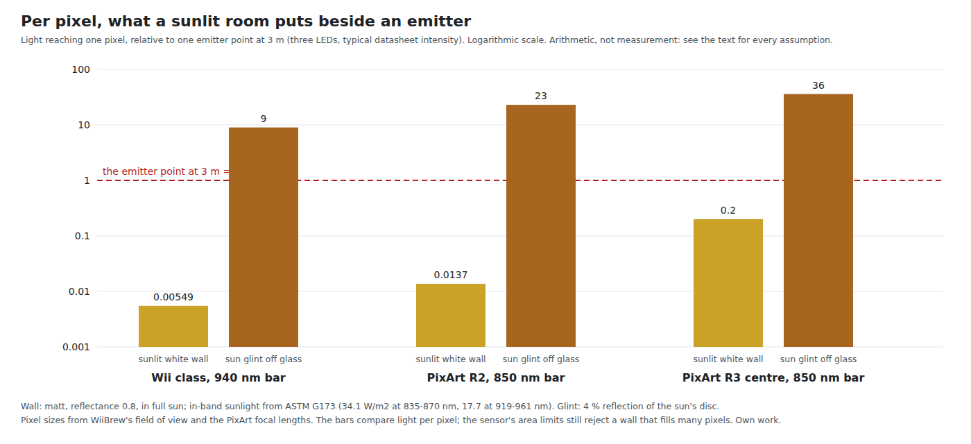
Per pixel, a sun glint off glass outshines an emitter nine to thirty-six times, and a sunlit wall comes within a factor of five for the wide-angle R3; filament lamps, remote controls, a second gun system and glossy furniture; the ways a point merges, splits, swaps or vanishes; and a symptom-to-fix table
5.1 The Defences the System Has
The sensor reports bright objects; it cannot say what they are (Volume 1). Everything that keeps a lamp from being taken for an emitter is one of five defences, three on the sensor and two in the firmware:
- The filter removes light outside the passband (Volume 2, 2.2). It does nothing against sources that emit in the passband, which is every hot object and every infrared LED.
- The brightness threshold ignores anything dimmer than it. It must sit below the dimmest emitter at the longest playing distance, so it cannot sit high.
- The area limits ignore objects that are too small (a hot pixel) or too large (a window, a lit wall). The PixArt driver in the OpenFIRE ESP32 port sets the maximum at 150 to 300 pixels (Volume 1, 1.8).
- Geometry. Four emitters form a plausible quadrilateral of known shape; a fifth point usually does not belong to it.
- Brightness and size per object, where the report carries them (the Wii camera’s Full format, the PAJ7025’s extended record): emitters look alike, interlopers usually do not.
OpenFIRE v6.2 uses the first four; it reads the Wii camera’s Basic format, which carries no brightness or size (Open-Source Firmware, Volume 2). The OpenFIRE ESP32 port reads the richer formats, which makes the fifth defence available to a fork.
5.2 Sunlight
Sunlight is the strongest interferer because it is both bright in the passband and arrives in two forms that defeat different defences.
A sunlit surface. A matt surface in sunlight is an extended source: it fills whatever pixels it covers with a level set by its brightness and by how large a patch of it each pixel sees. An emitter is a point source: its light lands on a few pixels whatever the camera. Comparing the two per pixel needs the pixel’s angular size and the surface’s radiance. Assumptions: a matt white surface of reflectance 0.8 in full sun; in-band sunlight from ASTM G173 (34.1 W/m² over 835 to 870 nm, 17.7 W/m² over 919 to 961 nm; Volume 2, 2.3); one emitter point of three LEDs at typical intensity at 3 m (150 mW/sr at 940 nm, 315 mW/sr at 850 nm); pixel angular size from WiiBrew’s field of view for the Wii class and from the datasheet focal lengths for the PixArt parts; all of the emitter’s light on one pixel. The emitter’s light per pixel divided by the wall’s:
Table 1 — A sunlit surface. A matt surface in sunlight is an extended source: it fills whatever pixels it covers with a level set by its brightness and by how large a patch of it each pixel sees. An emitter is a point source: its light lands on a few pixels whatever the camera. Comparing the two per pixel needs the pixel's angular size and the surface's radiance. Assumptions: a matt white surface of reflectance 0.8 in full sun; in-band sunlight from ASTM G173 (34.1 W/m² over 835 to 870 nm, 17.7 W/m² over 919 to 961 nm; Volume 2, 2.3); one emitter point of three LEDs at typical intensity at 3 m (150 mW/sr at 940 nm, 315 mW/sr at 850 nm); pixel angular size from WiiBrew's field of view for the Wii class and from the datasheet focal lengths for the PixArt parts; all of the emitter's light on one pixel. The emitter's light per pixel divided by the wall's
| Camera and bar | Pixel, angular size | Emitter at 3 m ÷ sunlit wall, per pixel |
|---|---|---|
| Wii class, 940 nm | 0.26° | about 180 |
| PixArt R2, 850 nm | 0.42° | about 70 |
| PixArt R3, centre of field, 850 nm | 1.67° | about 5 |
| PixArt R3, field average, 850 nm | 1.15° | about 10 |
The Wii-class camera’s tiny pixels and the dip in sunlight at 940 nm keep a sunlit wall nearly two hundred times below an emitter. Each R3 pixel at the centre of its field takes in a patch of wall about four times wider than an R2 pixel’s (fifteen times the area), and the wall comes within a factor of five to ten of the emitter. A threshold set to see emitters at 3 m is then only a few times above a sunlit wall, and any brighter patch (a white door frame, a lampshade in sun, a sunlit cushion) can cross it. The area limit rejects a wall that fills more than a few hundred pixels; it does not reject the small bright patches at a wall’s edges or a narrow sunlit strip. In practice the emitter’s light spreads over several pixels, which lowers its per-pixel level and makes these ratios optimistic.
A sun glint. Sunlight reflected specularly off glass, a glossy screen bezel, a picture frame or a car outside is a point source of extraordinary radiance. A 4 % reflection of the sun’s disc (bare glass at near-normal incidence) delivers to one pixel about 9 times the light of an emitter at 3 m for the Wii-class camera, 23 times for the R2 and 36 times for the R3. No threshold separates that from an emitter: it is brighter. Its only tells are its position (where no emitter should be) and, in a rich report, its size and brightness.
What this means. A light gun with any of these cameras will misbehave with direct sun in the room, and one with the R3 is more sensitive to a bright, sunlit room in general. That follows from the R3’s optics, not from any defect, and it is a case for the brightest bar the eye-safety and heat budgets allow, for curtains, and for the rich-report rejection rules of 5.1. Indoors the numbers are lower by whatever the glazing removes, which for coated modern glass can be much of the near infrared, and they apply only where sun actually falls.
5.3 Lamps and Flames
A tungsten filament is a small, very hot object: a point source in the passband. Planck’s law puts 1.9 % of a 2700 K lamp’s radiated power in the 835 to 870 nm band and 2.5 % in the 919 to 961 nm band (Volume 2, 2.3). For a 60 W bulb that is on the order of 80 to 110 mW per steradian, comparable to one emitter point. A halogen lamp at 3000 K puts a larger share of its output into both bands. Any visible incandescent or halogen bulb, or a filament seen through a lampshade, can be taken for an emitter at either wavelength.
Flames count too. WiiBrew’s Sensor Bar page: “Due to the sensor being IR-based, it can detect any IR signal as input, this include candles.”
Lamps that are not hot, LED and fluorescent ones, are not blackbodies, and how much each puts into the passband depends on its design. It is a measurement, and the room survey of Volume 6 makes it.
5.4 Remote Controls and Other Emitters
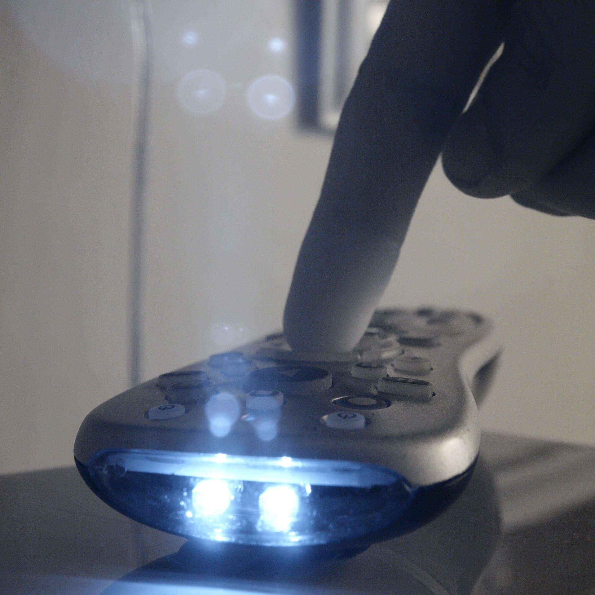
A television remote is an infrared LED pointed at the screen, which is to say pointed at the same place as the gun. Vishay’s application note on remote-control data formats describes the signals: data sent as bursts of a carrier, with carriers in common use at 30, 33, 36, 38, 40 and 56 kHz, and “no legal restrictions for IR transmission in the frequency band between 30 kHz and 56 kHz”. Two widespread codes illustrate the timing: RC5 bursts last 868 µs (32 cycles of 36 kHz), and the NEC code opens each command with a 9 ms burst at 38 kHz. Vishay’s remote receivers are characterised at 950 nm.
A camera exposing for 300 µs of each 4.8 ms frame (Volume 1, 1.7) catches a remote’s bursts in some frames and not others. The result is a bright extra point that flickers on and off for as long as a button is held, typically during an attempt to change volume in the middle of a game. With a Wii-class camera it is a fifth object that also makes real emitters drop out (“With more than four objects visible, the camera is prone to rapidly switching between some of them”, WiiBrew). Remote controls are a reason to keep the remote down, not a design flaw.
Other near-infrared emitters in a room behave the same way: another console’s sensor bar, a security camera’s night illuminator, a wireless-headphone transmitter. Each is a candidate fifth point if it is in the camera’s view when the gun aims at the screen.
5.5 Reflections
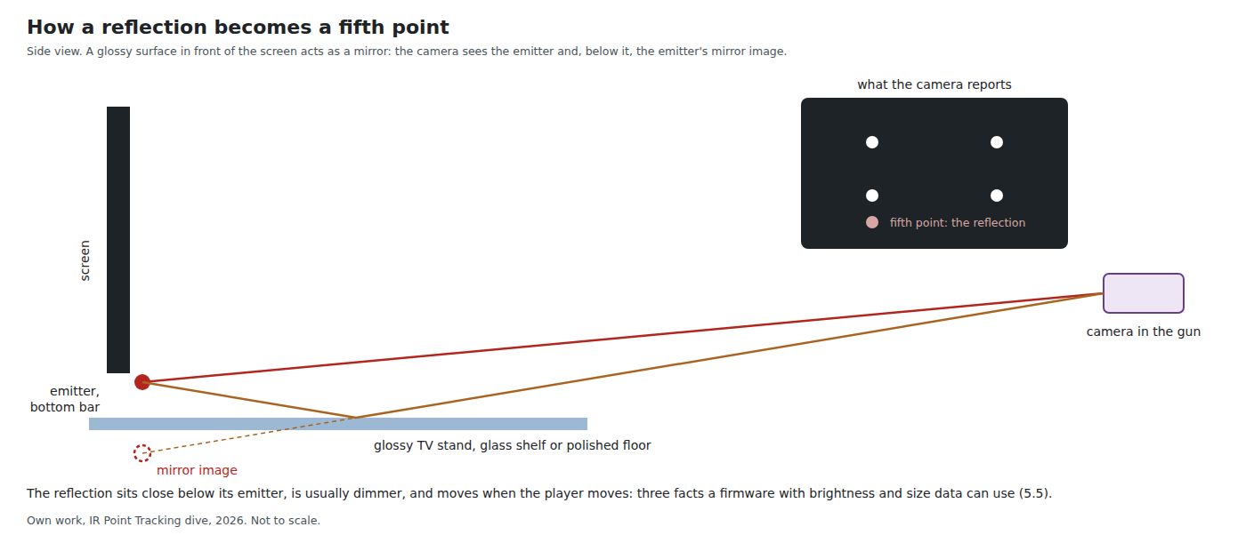
Every emitter is also a light source for the room, and a glossy surface in its beam returns some of that light toward the gun. The geometry is a mirror’s: a glossy TV stand, glass shelf or polished floor in front of the screen produces an image of each bottom emitter below the real one; a glossy bezel, a glass cabinet front or a window beside the screen does the same sideways. The photograph that opens Volume 2 shows the start of it, the Wii Sensor Bar’s light pooling on the surface beneath it.
OpenFIRE’s instruction book, quoted in Open-Source Firmware, Volume 5, describes the symptom: with sensitivity too high “the pointer jumps around erratically”, typically only when aiming at certain parts of the screen. That last detail is the signature of a reflection: it appears only from the angles at which the mirror geometry works. Its remedy is the right one: “Obviously, the best solution is to eliminate the reflective surface”, with sensitivity stepped down only if that is impossible.
Three properties distinguish a reflection from an emitter, and a firmware with brightness and size data can use all three:
- It is dimmer. A glossy surface at a grazing angle may reflect a few per cent to a few tens of per cent; the reflection is weaker than its emitter by that factor.
- It sits next to its emitter, on the far side of the reflecting surface: below a bottom emitter for a shelf, beside a side emitter for a window.
- It moves relative to the emitters when the player moves, because a mirror image’s position depends on the viewing angle, whereas the four real emitters keep their known shape.
The cheapest fixes are physical: a matt cloth over a glossy stand, the bottom bar moved to the top edge of a deep stand so the stand’s surface is behind the beam, the emitters’ beams aimed slightly up and toward the player rather than down across furniture.
5.6 Two Systems in One Room
Two light guns of the same kind sharing one set of emitters do not interfere: the cameras are passive and each sees the same four points. Two different systems with their own emitters do interfere: each camera sees both sets, eight points where it expects four.
Arcades met this when two cabinets stood side by side. Sega’s and Namco’s manuals for their infrared gun systems tell operators to set every other cabinet to an alternate “operating frequency” (Arcade Light Guns, Volume 4 quotes them), which implies emitters modulated at a frequency the gun’s receiver is tuned to. A camera-based home light gun has no such defence: its emitters run on steady current and its sensor takes short exposures, so it cannot tell its own emitters from anyone else’s.
The home equivalent of the arcade’s frequency jumper would be the PixArt sensor’s frame subtraction with a synchronised bar (Volume 1, 1.9): each gun would see only the emitters that flash in step with its own exposures. That is research for the Experimental Sensing dive. In the meantime the rule is one set of emitters per room, shared by every gun that understands that layout.
5.7 When the Points Themselves Misbehave
Not every failure comes from outside. The emitters and the sensor have their own:
Table 2 — Not every failure comes from outside. The emitters and the sensor have their own
| Failure | Mechanism | Where it is treated |
|---|---|---|
| A cluster splits | A point’s LEDs spaced more than about one pixel span apart image as separate blobs, each taking a slot | Volume 2, 2.6 |
| Two points merge | Two emitters closer in the image than a blob’s width become one object; with the square layout only at long range on a small screen | Volume 3, 3.6 |
| A point blooms | At close range a bright emitter saturates many pixels; its blob grows, its centroid is less certain, and if it exceeds the maximum area it is not reported at all | Volume 1, 1.8 |
| A point vanishes at the edge | Aimed at a corner from too close, the far emitters leave the field of view; at the edge of the R3’s field the lens passes 38.5 % of the light | Volume 4, 4.2 and 4.3 |
| Slots switch | More than four objects in view makes a Wii-class camera switch between them from frame to frame | 5.4, Volume 1, 1.4 |
| Points swap identity | Roll beyond ±45° exchanges the quadrants a median sort assigns | Volume 3, 3.6 |
| A torn read | The Wii-class camera updates its registers during a read; mixed bytes give impossible coordinates | Reference Electronics, Volume 3, 3.5 |
| Too hot | The PAJ7025R3 is specified for 0 to 40 °C; the SFH 4547 loses about 0.5 % of output per kelvin | Reference Electronics, Volume 3; Volume 2, 2.4 |
| A dirty window | A fingerprint on the camera’s window scatters light into a halo, enlarging and dimming blobs | 5.8 |
| A loose camera | A mount that flexes under the solenoid’s kick moves the aim for the duration of the kick | Reference Electronics, Volume 3, 3.7 |
5.8 Symptoms, Causes and Fixes
The first tool for every row is the IR test view, in the OpenFIRE App or the ESP32 port’s web app, which shows the points as the camera sees them (Open-Source Firmware, Volume 5).
Table 3 — 5.8 Symptoms, Causes and Fixes
| Symptom | Likely cause | Check | Fix |
|---|---|---|---|
| Cursor jumps, only when aiming at some parts of the screen | Reflection of an emitter | IR test view from the playing position: an extra point near an emitter that moves as the gun moves | Remove or cover the glossy surface; re-aim the bar; then lower sensitivity |
| Cursor jumps in daytime only | Sunlight on a surface, or a glint | IR test view with curtains open and closed | Curtains; move the glint source; brighter bar |
| Cursor jumps when the lamp is on | Filament lamp in view | IR test view with the lamp on and off | Move or shade the lamp; use an LED lamp |
| Cursor flickers while someone uses the remote | Remote-control bursts | Hold a remote button with the IR test view open | Keep the remote out of the gun’s view |
| Cursor moves in coarse steps | Emitters too dim, or sensitivity too low, so blobs are one or two pixels | Brightness and area of each point in a rich report, or Volume 6’s centroid-noise test | Brighter bar (more current, more LEDs, better bin); raise sensitivity |
| Cursor drifts or jumps near corners from close range | Emitters leaving the field; reconstruction in use | IR test view aimed at each corner | Stand further back, or use the wide-lens camera |
| Points drop out at the back of the room | Below threshold at that distance | Note the distance at which each point goes | Brighter or matched emitters; more gain |
| One point drops out before the others | Mismatched emitters (bin, current, aim) | Compare per-point brightness | Constant-current drive; matched LEDs; re-aim |
| Aim shifts on every shot | Camera mount flexing under recoil | Look at the IR test view while firing | Stiffen the mount |
| Everything worse than yesterday | Dirty camera window | Look at it | Clean it |
5.9 Rules for the Room
From the sections above, in order of payoff:
- One set of emitters per room, and no other infrared emitters in the camera’s view.
- No direct sun on anything the gun sees, and no sun glints: close curtains for daytime play, especially with the R3.
- No bare filament bulbs or flames in view behind or beside the screen.
- No glossy surfaces in front of the bars; cover them or move the bars.
- Stand within the envelope of Volume 4 for the camera in use.
- Keep the remote down while playing.
5.10 What Could Not Be Verified
- Every ratio in 5.2 and 5.3 is arithmetic from stated assumptions; none was measured. The emitter’s light is assumed to fall on one pixel, which flatters the emitter.
- The near-infrared content of LED and fluorescent lamps in the room; Volume 6 measures it.
- Whether the gun cameras’ lenses produce ghost images from a strong source, as the photographer’s lens did in the photograph above.
- The real reflectance of common furniture finishes at 850 and 940 nm.
- What OpenFIRE’s tracking does when a fifth point coincides with a real emitter’s expected position.
Sources
- ASTM G173-03 reference spectra (pvlib-python copy), Planck’s law, and the radiometric arithmetic in the dive’s
04-templates/calc_radiometry.py, 2026-10-19. - WiiBrew wiki, Wiimote (“IR Camera”, data formats) and Sensor Bar, https://wiibrew.org, wikitext read 2026-10-19.
- Vishay Semiconductors, Data Formats for IR Remote Control, document 80071, Rev. 2.3, 26 June 2024, https://www.vishay.com/docs/80071/dataform.pdf, read 2026-10-19; Vishay TSOP382 datasheet (test wavelength 950 nm).
- PixArt Imaging, PAJ7025R2 and R3 datasheets as described in Volume 1 (optics, temperature range).
- Alessandro Satanassi, OpenFIRE-Firmware-ESP32,
lightgun/src/OpenFIRECamera.cpp(area limits), read 2026-10-19. - OpenFIRE instruction book, as quoted in Open-Source Firmware, Volume 5.
- Sega, The House of the Dead III and Namco, Time Crisis 4 operator manuals, as quoted in Arcade Light Guns, Volume 4.
- Inm8, Infrared LEDs on Remote, Wikimedia Commons, CC BY-SA 3.0.
Comments (0)