Solenoid Recoil · Volume 4
Driving It — Pulse Width, Heat, Overdrive, Regulated Current and the Flyback Clamp
What a fixed-voltage pulse actually does to a moving plunger, how long a recoil coil can be fired before it cooks, why regulating current removes most of the unit-to-unit spread, and how the turn-off clamp sets the release
This volume is the electrical half of the dive. It explains, at the level of the coil’s own equation, what happens when the firmware raises the solenoid pin; why the default pulse widths in the open firmware waste most of their energy; how hot a recoil coil gets and how fast; what overvoltage drive, peak-and-hold and current regulation each buy; and how the flyback clamp decides how quickly the plunger lets go. The circuits that implement these drives are designed in the Reference Electronics dive, and the supplies that feed them in Power Supplies. The numbers here come from the dive’s lumped model of a generic 30 mm open-frame solenoid, an 8 Ω, 10 mm stroke part, unless a source is cited; the model is a teaching tool, and Volume 6 shows how to replace its numbers with measured ones.
4.1 The coil’s own equation
A solenoid’s coil voltage is
v = R·i + (∂λ/∂i)·di/dt + (∂λ/∂x)·dx/dt
where λ is the flux linkage, which depends on both current i and plunger position x. The first term is the resistive drop. The second is the familiar inductive term, with an incremental inductance that is several times larger with the plunger closed than open, and falls again as the iron saturates. The third is the speed voltage: while the plunger is moving into the coil, the rising flux linkage generates a back-EMF in proportion to the plunger’s speed. That term is what makes a solenoid’s current waveform informative. While the plunger accelerates, more of the applied voltage is taken up by speed voltage and the current falls; when the plunger hits its stop, the speed voltage vanishes and the current resumes its climb. The arrival shows as a sharp minimum in current, the cusp.
4.2 One shot, step by step
The figure below is the lumped model fired once at 12 V and once at 24 V, with OpenFIRE’s default on-time of 45 ms and a plain flyback diode.1
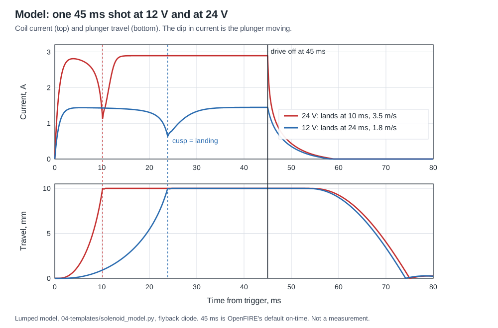
At 24 V: the current climbs on the open-plunger time constant, about 1 ms; the force exceeds the spring preload and friction at about 1.2 ms and the plunger starts to move. It accelerates, the speed voltage pulls the current down from nearly 2.9 A to about 1.1 A, and the plunger lands at 10.1 ms at about 3.5 m/s, carrying about 48 mJ of kinetic energy. The current then recovers to V/R, 2.9 A, and stays there until the pulse ends at 45 ms.
At 12 V: everything is slower and weaker. The plunger starts at 2.6 ms, lands at 23.9 ms at 1.8 m/s, and carries about 13 mJ. Doubling the voltage nearly doubled the speed, nearly quadrupled the impact energy and cut the travel time to less than half.
4.3 Pulse width: everything after landing is heat
Once the plunger is seated, the coil does no more mechanical work. Every joule delivered after the cusp heats the coil. In the model at 24 V the 45 ms pulse delivers 2.84 J from the supply, of which 0.56 J arrives before the plunger lands. Ending the pulse 2 ms after landing, at 12.1 ms, gives exactly the same impact speed for 0.65 J: four and a half times less heat per shot, for the same kick.
Table 1 — Pulse width: everything after landing is heat
| Drive | Lands at | Impact speed | Energy per shot | Heat after landing |
|---|---|---|---|---|
| 12 V, 45 ms | 23.9 ms | 1.82 m/s | 0.69 J | about half |
| 24 V, 45 ms | 10.1 ms | 3.48 m/s | 2.84 J | about 80 % |
| 24 V, 12.1 ms (landing + 2 ms) | 10.1 ms | 3.48 m/s | 0.65 J | small |
The lesson generalises beyond the model. The right pulse width is the arrival time plus a small margin, and the arrival time depends on the solenoid, the moving mass, the spring and the supply voltage. A pulse width copied from someone else’s gun is right only by accident. OpenFIRE’s default of 45 ms is a safe choice for a slow 12 V part, which may need most of that to land; on a fast 24 V setup most of it is heat. Measure the cusp (Volume 3, step 5; Volume 6) and set the pulse from it.
There are two refinements. A pulse can end slightly before landing, because the plunger coasts and, with a diode clamp, the decaying current keeps pulling for several milliseconds after turn-off; for a heavy striker this can cost very little speed. And a pulse that ends too early in the stroke gives an inconsistent kick, because the plunger’s speed then depends on where it was when the force fell away.
4.4 Repetition rate and the full cycle
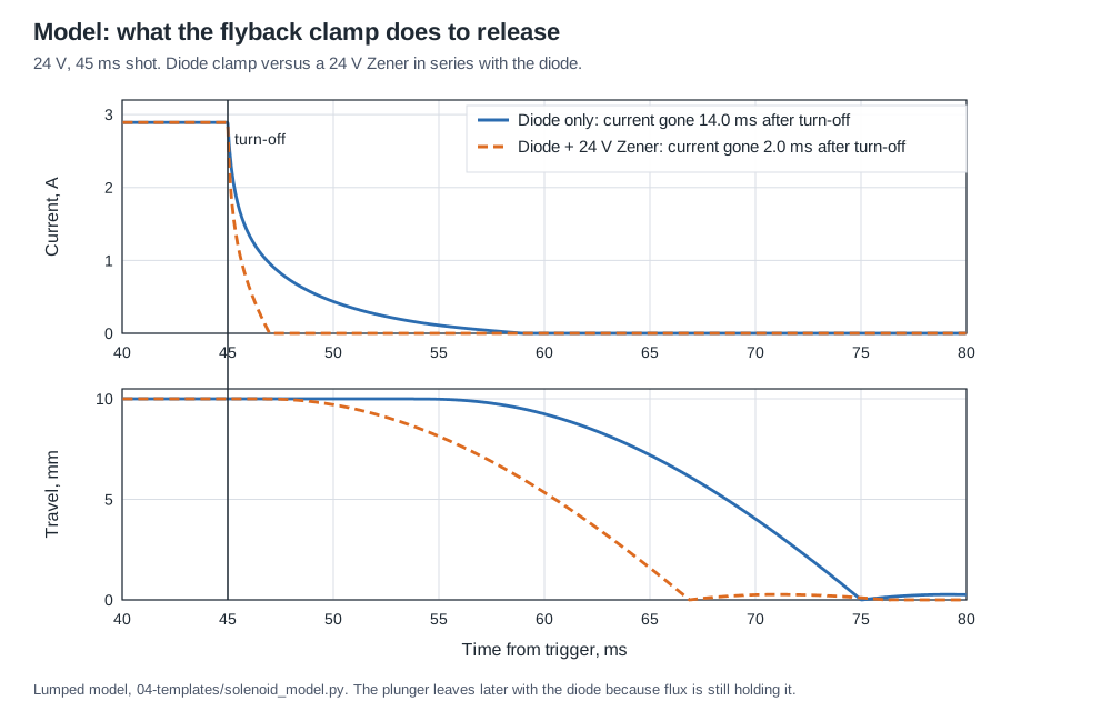
A shot is not over when the plunger lands. The current has to decay, the field has to release the plunger, and the spring has to return it before the next shot can start from rest. In the model with a 12.1 ms pulse at 24 V, the plunger is home again at 42 ms with a diode clamp and 34 ms with a 24 V Zener clamp. That puts a ceiling of roughly 24 to 30 shots a second on this part, before heat is considered; a heavier striker or a weaker spring lowers it.
OpenFIRE’s held-trigger cadence is 45 ms on and 80 ms off, a 125 ms period or 8 shots a second, after a 500 ms pause following the first shot; in its autofire mode it doubles the off-time.1 RetroShooter’s RS3 Reaper offers a two-position “recoil frequency” switch alongside its “recoil force” switch.2 Both are setting the same two numbers, pulse width and period. If a game fires faster than the mechanism can cycle, the plunger is re-energised before it is home, starts with less stroke to go, and lands with less energy: the kick softens into a buzz. Matching the firmware’s rate to the measured cycle time avoids it.
4.5 Duty cycle and coil heating
Volume 2 showed that a solenoid’s voltage rating is a thermal rating: the Ledex B14’s one coil is rated at 12 V for 100 % duty and 38 V for 10 %, because duty cycle times pulse power equals the same 5.2 W in every case.3 The same reasoning applies to a recoil coil in a gun. Its temperature is set by the average power, which is the energy per shot times the shots per second, against how well the coil can shed heat.
A first-order thermal model makes the behaviour clear. Lump the coil and its frame into a heat capacity C, joules per kelvin, connected to the air by a thermal resistance R_th, kelvin per watt. The temperature rise then approaches P_avg·R_th with time constant R_th·C. For a small open-frame part, a heat capacity of the order of 10 J/K and a thermal resistance to still air of the order of 30 K/W are plausible assumptions; no hobby part publishes either, and they should be measured (Volume 3, step 6). With those assumptions, and the energy per shot from the model:
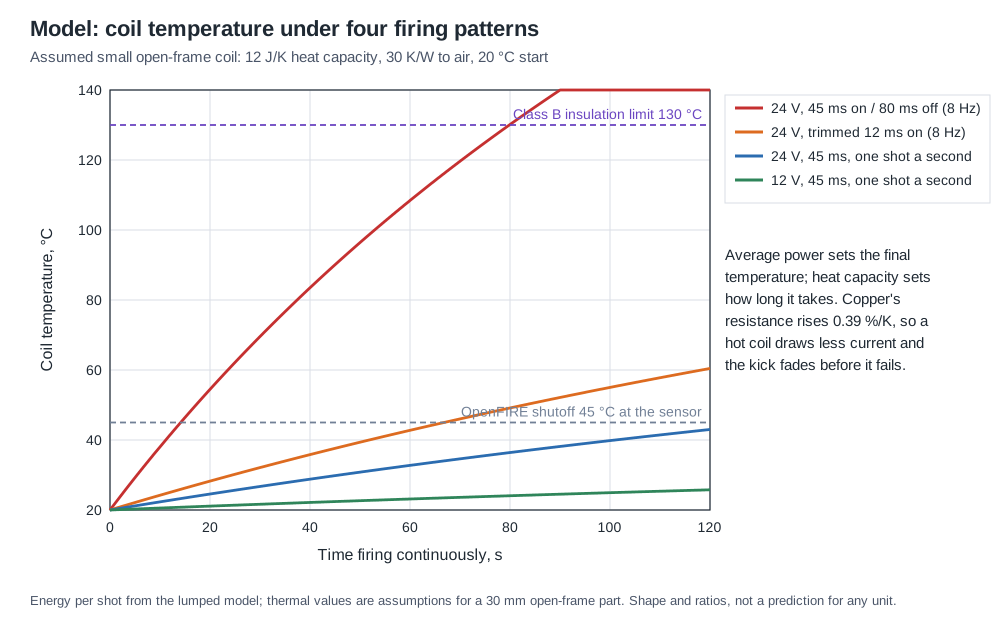
Table 2 — Duty cycle and coil heating
| Pattern | Average power | Time to +25 °C (approx.) | Final rise if sustained (approx.) |
|---|---|---|---|
| 24 V, 45 ms on, 8 shots/s | about 23 W | about 15 s | far beyond any insulation class |
| 24 V, 12 ms on, 8 shots/s | about 5 W | about 65 s | beyond Class B |
| 24 V, 45 ms, 1 shot/s | about 2.8 W | about 2 min | about 85 °C rise |
| 12 V, 45 ms, 1 shot/s | about 0.7 W | many minutes | about 20 °C rise |
Three conclusions survive any reasonable change to the assumed numbers:
- Sustained automatic fire at full pulse width is not thermally possible for a small coil overdriven to 24 V. The arcade guns lived with it because games ration fire; Ghost Squad’s manual warns that the solenoid “may become hot” enough to burn.4 A gun that will be used for automatic fire needs trimmed pulses, a temperature sensor, or both.
- Copper’s resistance rises about 0.39 % per kelvin, so at fixed voltage a hot coil draws less current and makes less force. A coil at 70 °C has lost a fifth of its energy per shot (Volume 3). The kick fades before the coil fails, which is a warning sign worth noticing.
- The shell sets a lower limit than the coil. Class B insulation is rated to 130 °C, but a printed PLA shell softens at around 60 °C. A coil that is merely warm by its own standards can deform the mount that holds it. Mount the coil to metal or to a higher-temperature polymer, give it air, and keep the hottest face away from the plastic.
4.6 Temperature sensing and its lag
OpenFIRE supports a TMP36 analogue temperature sensor on the solenoid. It reads it every 250 ms, averages four readings, and above a warning threshold of 38 °C doubles the off-time; at 45 °C it stops firing until the reading falls 5 °C below the threshold. An out-of-range reading is treated as fatal and also stops firing.1 GUN4IR’s assembled guns mount “a temperature sensor on the solenoid as a safety measure”, and its boards have an input for one.5
Those thresholds are low, and they are low for a good reason. The sensor sits on the frame or the tape outside the winding, and the winding is hotter than its surface; the difference grows with power and lags the winding by the thermal time constant of the path between them. A 45 °C reading on the outside can mean a considerably hotter winding during a burst. The resistance method gives the true average winding temperature (Volume 3, step 6), and the two measured together on the bench tell the builder how much margin the firmware’s thresholds really leave. A firmware that tracked coil resistance from the current waveform could estimate winding temperature directly; none of the firmwares examined does so.
The protection also has gaps that a reading of the source shows. In SolenoidActivation, the first shot of each trigger pull takes a separate path, commented “it’s probably safe to shoot regardless of temps”, that energises the coil without consulting the temperature status; the cut-out therefore stops held and automatic fire but not a player who fires by repeated single pulls.1 The Open-Source Firmware dive’s Volume 5 reads the same code in detail and reports two further points that bear on heat: the burst-fire off-time evaluates to about 1 ms because of an operator-precedence error, which would make a burst close to continuous drive, and a serial command can hold the solenoid on for 2 s. Those are source readings, not yet confirmed on the bench; until they are, the solenoid’s thermal safety in an OpenFIRE gun should not rest on the firmware alone.
4.7 Overvoltage drive
Running a “12 V” coil from 24 V is the light-gun community’s universal practice and the arcade guns’ practice before it. Volume 2 explained why it works: force at the start of the stroke goes as (NI)², so twice the voltage gives about four times the starting force and a much faster start, while the saturated force near closure rises much less. It is safe exactly as long as the average power and the length of any one pulse stay within what the coil can take. The Ledex table expresses that directly: a coil rated 12 V at 100 % may be run at 24 V at 25 % duty, with no single pulse longer than 36 seconds when pulsed continuously.3 A recoil pulse of 10 to 50 ms is far inside the single-pulse limit; it is the average that has to be watched.
Overvoltage has one hazard that has nothing to do with heat on a normal day: a driver that fails switched on. A MOSFET that fails short, a firmware bug that leaves the pin high, or a gate that floats high at power-up applies the full overvoltage continuously. A 12 V coil on 24 V then dissipates four times its continuous rating and will burn. Namco fitted a thermal fuse to its coil;6 OpenFIRE’s temperature check turns the pin off but cannot help if the MOSFET itself has failed, and, as Section 4.6 notes, it does not gate the first shot of a trigger pull.1 Volume 7 returns to this with the protective options, including the honest reading of Ultimarc’s “no more than 4 A” supply rule.
4.8 Peak and hold
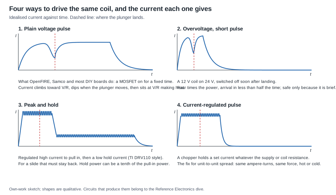
Texas Instruments’ DRV110 and DRV120 are current controllers built for solenoids, relays and valves. Their datasheets describe the scheme in a sentence: “The solenoid current is ramped up fast to ensure opening of the valve or relay. After initial ramping, the solenoid current is kept at a peak value to ensure correct operation, after which the current is reduced to a lower hold level to avoid thermal problems and reduce power dissipation.” The time at peak is set by a capacitor, the peak and hold levels and the PWM frequency by resistors; the default PWM frequency is about 20 kHz. The DRV110 drives an external MOSFET through a sense resistor and so suits any current; the DRV120 integrates the switch and sense resistor, with a default peak of about 200 mA, which is relay territory rather than recoil.78
Peak and hold matters to a light gun in one situation: when something has to stay energised. A slide that should lock back on an empty magazine, or a moving ejection port that should stay open for the length of a burst, needs the plunger held against its spring. Because a seated plunger has the steep end of the force-stroke curve in its favour (Volume 2), the hold current can be a fraction of the pull-in current, and the hold power a fraction again, since power goes as current squared. A recoil kick that releases straight away does not need peak and hold at all. What it can use from the same idea is the first half: a regulated peak.
4.9 Regulated current: the cure for spread
Volume 3 listed the reasons two “identical” solenoids kick differently on a fixed voltage: coil resistance, temperature, wiring, supply sag. All of them act through the current. A driver that regulates current instead of applying a fixed voltage sets the ampere-turns directly, and with them the force, and the reasons drop out.
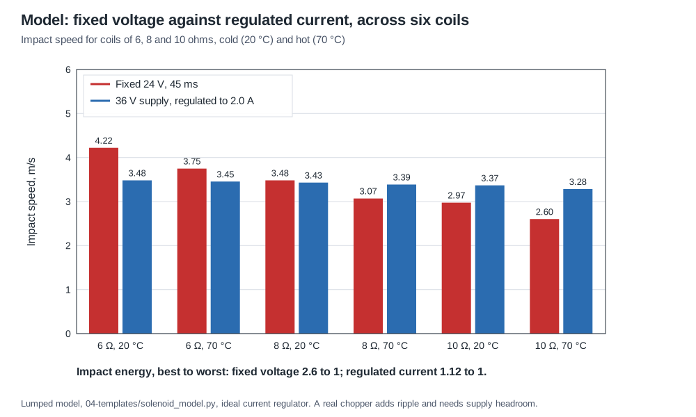
In the model, six coils between 6 and 10 Ω, at 20 °C and at 70 °C, give impact energies spread over 2.6 to 1 on a fixed 24 V supply. The same six on a 36 V supply with the current regulated to 2.0 A give 1.12 to 1. That is the electrical answer to the drawer of power supplies: one supply, one current setting per gun, and every solenoid in the batch kicks within about a tenth of every other.
Regulation has requirements of its own:
- Headroom. The supply must be well above I·R for the hottest, highest-resistance coil, or the regulator saturates and the scheme reverts to fixed voltage. It must also be high enough to slew the current up quickly through the coil’s open-plunger inductance: di/dt = V/L, so 36 V across 7 mH reaches 2 A in about 0.4 ms, while 12 V needs about three times as long. This is one reason the AimTrak asks for 24 to 36 V.9 The 36 V in the figure above is not essential: what regulation needs is a supply about twice the hot coil’s I·R. Volume 8 shows that on 24 V the same six coils regulated to 2.0 A spread 1.57 to 1, because the hot 10 Ω coil runs out of headroom, and that a lower-resistance winding at 1.5 times the current restores the 1.12 to 1 exactly; it settles the choice of rail from that.
- A chopping frequency above hearing. A coil chopped at a few kilohertz sings. TI’s controllers default to about 20 kHz; anywhere from 20 to 50 kHz is out of earshot and comfortably above the coil’s electrical time constants.
- Slow decay while chopping, fast decay at the end. During regulation the current recirculates through the flyback diode between PWM pulses (TI’s datasheet calls for a fast-recovery recirculation diode8), which keeps ripple small. At the end of the shot a fast-decay path is wanted; Section 4.10 covers it.
- The pulse still ends at landing. Regulation fixes the force; the on-time still has to be set from the measured arrival, or the coil still spends the remainder of a long pulse making heat.
A microcontroller can implement all of this with a MOSFET, a sense resistor and a comparator or ADC, which is the Reference Electronics dive’s problem. The theory here is enough to specify it: regulated peak current, settable per gun; on-time from the measured cusp; fast decay at turn-off.
4.10 Turn-off: diode, Zener and TVS clamps
When the switch opens, the coil’s stored energy keeps the current flowing, and the voltage across the coil rises until something conducts. Without a clamp it rises until the MOSFET avalanches or something arcs; TE Connectivity’s relay application note describes uninterrupted coil voltages “of the order of hundreds or even thousands of volts”.10 Every DIY guide therefore puts a diode across the coil. It is the safe choice, and it is the slowest.
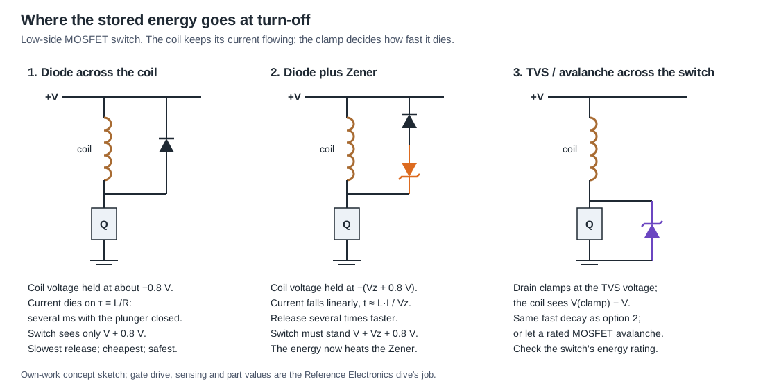
With a plain diode, the coil voltage during decay is only the diode’s forward drop. The current decays with the coil’s own time constant, L/R, and with the plunger seated, L is at its largest: in the model, about 44 mH against 8 Ω, a time constant over 5 ms. The current takes about 14 ms to reach zero, and while it flows it holds the plunger against the spring. TE’s application note on relay coil suppression makes the same point about relays: the slowest decay “is experienced with a simple diode shunt across the coil”, and it can slow, stop “or even momentarily reverse” the armature’s release.10
With a Zener in series with the diode, the coil is held at the Zener voltage plus a diode drop during decay. The current then falls almost linearly, at a rate of roughly V_Z/L, so the decay time is about L·I/V_Z. TE calls a Zener-plus-diode clamp a “near optimum decay rate”.10 In the model, a 24 V Zener ends the current in 2 ms instead of 14, and the plunger starts home correspondingly sooner:
The trade-offs are straightforward and they all land on the switch:
- Voltage rating. With a Zener clamp the MOSFET’s drain sees V_supply + V_Z + V_diode at turn-off. On a 24 V supply with a 24 V Zener that is about 49 V; the MOSFET needs a 60 V rating at least, and the measurement equipment must be able to see it (Volume 6).
- Where the energy goes. With a diode the stored magnetic energy is dissipated mostly in the coil’s own resistance. With a Zener most of it goes into the Zener. In the model the stored energy with the plunger seated at 2.9 A is about 0.06 J; at eight shots a second that is about half a watt in the Zener, which a small through-hole Zener or a TVS rated for repetitive pulses must survive.
- A TVS across the switch does the same job from the other side: the drain is clamped at the TVS voltage, and the coil sees that voltage minus the supply. Some MOSFETs are rated for repetitive avalanche and can absorb the energy themselves; that is a datasheet check, not an assumption.
Fast release matters for the rate of fire and for the feel of the forward stroke. It does not change the kick of the shot already fired, which was settled when the plunger hit its stop.
4.11 Where the pulse energy comes from
A 24 V shot that draws about 3 A for 10 to 45 ms is a large, short load. The model’s shots take between 0.6 and 2.8 J from the supply. Supplied directly, that needs a supply whose transient response and over-current protection tolerate the pulse; GUN4IR’s request for a “non switching if possible” supply is consistent with switching bricks whose protection trips or hiccups on a pulse, though GUN4IR does not give a reason.5 Supplied from a capacitor, the bank must hold the shot’s energy with an acceptable sag: a capacitor C charged to V₁ and discharged to V₂ gives up ½·C·(V₁² − V₂²). Sinden’s USB-powered recoil is the existence proof of the capacitor approach and of its limit in sustained fire (Volume 1). The sizing of supplies, boost converters and capacitor banks is the Power Supplies dive’s subject; this dive’s contribution is the energy per shot, which trimming the pulse to the landing cuts by a factor of about four.
4.12 Wiring, ground and the USB disconnect
OpenFIRE’s README warns that the “Solenoid may cause EMI disconnects with too thin of wiring”, asks for the solenoid run to be “24AWG at its thinnest”, and explains that thinner cables “will become antennas under extended use, which will trip USB safety thresholds in your PC”.11 The symptom, a gun that drops off USB when the solenoid fires, is widely reported. The README’s explanation is the project’s; the more conventional one is less exotic. Thin wire adds series resistance and loop inductance to a circuit switching amperes in microseconds. If the solenoid’s return shares a conductor with the microcontroller’s ground, the I·R and L·di/dt drops on that conductor appear as ground bounce at the microcontroller and the USB transceiver. A large current loop also couples into nearby signal wiring. The cures are those of any pulsed load: a short, twisted supply-and-return pair for the solenoid, a separate return to the supply’s negative terminal with the logic ground joined at one point, local bulk capacitance at the driver, and a gate pull-down so the switch cannot float on at power-up. The OpenFIRE build guide in this project’s brief gives the same practical rules: separate supply, flyback diode, common ground, gate pull-down.12
4.13 Settings to start from
These are starting points for a small open-frame solenoid on a 24 V supply, to be replaced by measured values:
Table 3 — These are starting points for a small open-frame solenoid on a 24 V supply, to be replaced by measured values
| Setting | Start at | Then |
|---|---|---|
| Pulse width | 15–20 ms | Measure the cusp; set to arrival + 2–5 ms |
| Period in held fire | 125 ms (OpenFIRE default) | Not shorter than the measured full cycle |
| Flyback | Diode | Add a Zener of about the supply voltage if the return is too slow; check the switch rating |
| Temperature cut-off | OpenFIRE’s 38 °C / 45 °C at the sensor | Raise only after measuring winding against sensor temperature |
| Drive | Fixed voltage | Move to regulated current to equalise guns |
4.14 Why this, and why not the others
Table 4 — Why this, and why not the others
| Choice | Picked | Alternatives and why they lost |
|---|---|---|
| Drive strategy, bench before the first driver board | Fixed voltage, pulse ended at the measured landing time plus 2–5 ms | Fixed 45 ms default: about four-fifths of a 24 V shot’s energy becomes heat after landing (Section 4.3). Peak and hold: only needed when something must stay energised, such as an ejection port held open |
| Drive strategy, from the first driver board | Regulated current from a 24 V-class rail; decided 18 October 2026 (D13, D14; Volume 8) | Fixed voltage: leaves coil resistance, temperature, wiring and supply sag in the kick, a 2.6 to 1 spread in the model (Section 4.9) |
| Turn-off clamp | Diode across the coil to start; a Zener in series, or a TVS from drain to ground, when the release must be faster | Diode alone: safest, but about 14 ms of release in the model. A TVS across the coil: puts supply plus clamp on the switch, which can exceed a 60 V MOSFET on 24 V (see the Reference Electronics dive). The MOSFET’s own avalanche rating: acceptable only where the datasheet rates repetitive avalanche |
| Thermal protection | A sensor on the coil read by firmware, plus an independent limit that does not rely on the switch (Volume 7) | A sensor alone: cannot help when the switch fails short. A thermal fuse alone: one-shot, and opens only after the damage starts |
4.15 What could not be verified
- Thermal constants for the hobby parts. No heat capacity or thermal resistance is published for any of them; the figures used here are assumptions, and the temperature plot is a shape, not a prediction.
- Whether any light-gun firmware or commercial gun regulates solenoid current. None of the sources read says so; Sinden’s “complex innovative solenoid circuit” is undescribed.
- The reason for GUN4IR’s preference for non-switching supplies. Not stated by GUN4IR.
Sources
Footnotes
-
TeamOpenFIRE, OpenFIRE-Firmware,
OpenFIREmain/OpenFIREprefs.h(default settings: solenoid on 45 ms, off 80 ms, hold 500 ms, temperature warning 38 °C, shutoff 45 °C) andOpenFIREmain/OpenFIREFeedback.cpp(SolenoidActivation,TemperatureUpdate);OpenFIREFeedback.h(TMP36, 250 ms polling). BranchOpenFIRE-dev, read 2026-10-18. ↩ ↩2 ↩3 ↩4 ↩5 -
RetroShooter, RS3 Reaper DIP-switch settings image, https://retroshooter.com/wp-content/uploads/2024/11/RS3-Reaper-Dip-Settings.jpg, read 2026-10-18. ↩
-
Ledex (Johnson Electric), Ledex® Box Frame Size B14 datasheet, copy at https://media.e-sonic.com/productfiles/mf-jon/openframe_b14.pdf, read 2026-10-18. ↩ ↩2
-
Sega, Ghost Squad manual (disclosed 2004), cautions and “Replacing the Solenoid”. Internet Archive item
sega-ghost-squad, read 2026-10-18. ↩ -
GUN4IR / JB Game Lab online store product data, https://www.gun4ir.com/products.json, read 2026-10-18. ↩ ↩2
-
KLOV / Arcade Museum forum, “Replacing solednoid in Time Crisis Namco Gun?”, 17 January 2019, https://forums.arcade-museum.com/threads/replacing-solednoid-in-time-crisis-namco-gun.443665/, read 2026-10-18. ↩
-
Texas Instruments, DRV110 120- and 230-V AC, 6- to 48-V DC Current Controller for Solenoids, Relays, and Valves, SLVSBA8G, March 2012, revised March 2018, https://www.ti.com/lit/ds/symlink/drv110.pdf, read 2026-10-18. ↩
-
Texas Instruments, DRV120 Single-Channel Relay, Solenoid, Valve Low-Side Driver With Current Regulation, SLVSBG3C, June 2012, revised June 2016, https://www.ti.com/lit/ds/symlink/drv120.pdf, read 2026-10-18. ↩ ↩2
-
Ultimarc, “AimTrak Light Gun With Recoil”, https://www.ultimarc.com/light-guns/aimtrak-light-gun/aimtrak-light-gun-with-recoil/, read 2026-10-18. ↩
-
TE Connectivity, “Relay coil suppression and relay life” application note, 13C3264_AppNote, September 2020, https://www.te.com/en/products/relays-and-contactors/relays/intersection/coil-suppression-relay-life.html, read 2026-10-18. ↩ ↩2 ↩3
-
TeamOpenFIRE, OpenFIRE-Firmware README, branch
OpenFIRE-dev, read 2026-10-18. ↩ -
“Build a DIY OpenFIRE lightgun with recoil”, build guide and project memory note written for this project in a separate session, 2024–2026, held in the Open-Source Firmware dive’s inputs. Its prices are an unverified forum figure and are not used here. ↩

Comments (0)