Solenoid Recoil · Volume 3
The Parts Actually Used — Generic Open-Frame Solenoids, What Their Listings Get Wrong, and Why No Two Kick Alike
The JF-0530B and JF-0826B families and their retail cousins, one honest Chinese specification sheet, the sources of unit-to-unit spread, and a bench procedure that turns a nameless part into a characterised one
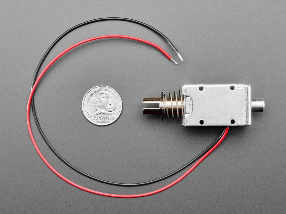
The solenoids in home-built light guns are not Ledex parts with published curves. They are generic open-frame units bought for a few dollars from marketplace sellers, or the same parts resold with better photographs by the hobby electronics retailers. This volume looks at what is actually sold, what the listings claim, and why two parts with the same name and the same listing behave differently in the same gun. It ends with a bench procedure that measures everything a listing should have stated.
3.1 The families on sale
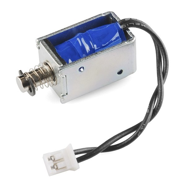
The parts that appear in light-gun builds fall into a few recognisable shapes. Model numbers in this market are not a maker’s catalogue but a widely copied naming convention: the same body is sold as “JF-0530B”, “TAU-0530B” or simply “0530B”, and “JF-0826B” listings show more than one body. Treat the name as a size class, not a specification.
Table 1 — The families on sale
| Class (common names) | Body, approx. | Stroke | Typical listed force | Seen in |
|---|---|---|---|---|
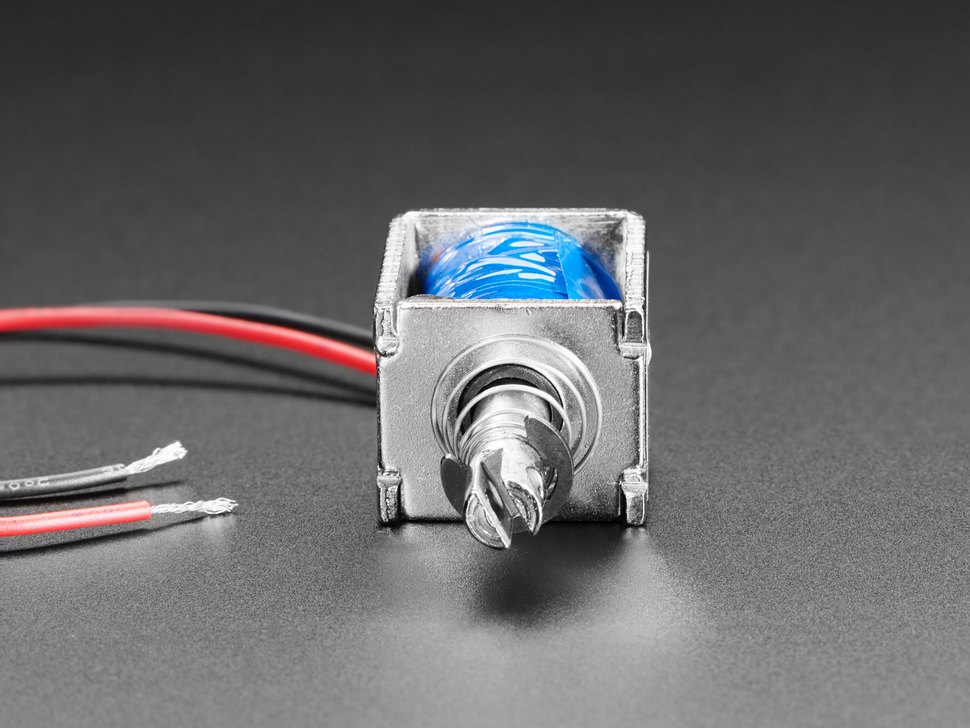
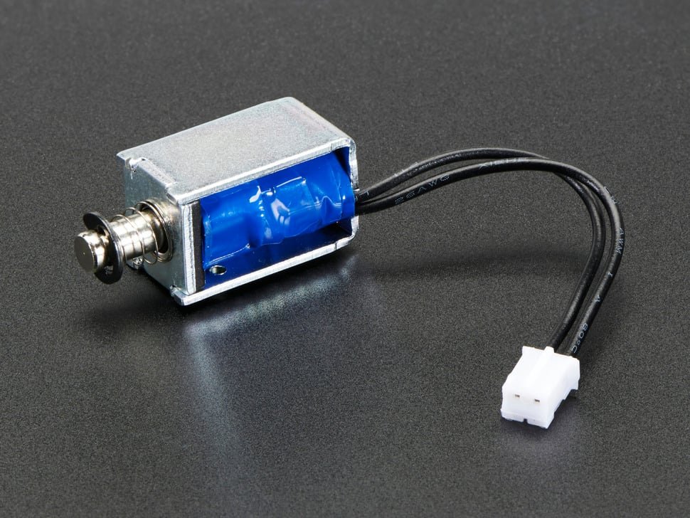
| Mini 5 V push-pull (ZHO-0420S, SparkFun ROB-11015, Adafruit 2776) | 20 mm | 4.5–6 mm | under 1 N at full stroke | Toys, small hammers |
| ”0530B” open frame | 30 × 15 × 13 mm | 10 mm | ”5 N” | Most DIY light-gun kicks |
| ”0826B” open frame | 26 × 25 × 22 mm | 10 mm | ”20 N” | Blamcon Ace of Spades hammer |
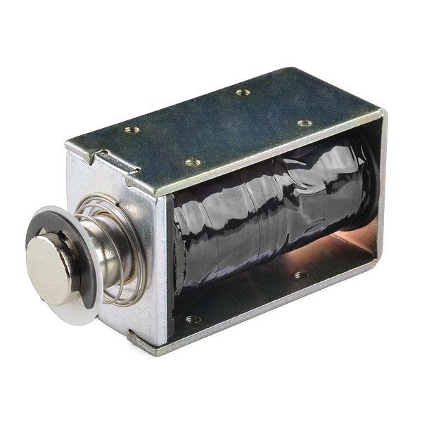
| Large box frame (Adafruit 413, TAU1040T) | 40 mm | 10 mm | ”6 N starting” | Heavier strikers |
| Tubular with threaded boss | various | various | various | Arcade guns (Namco ST-0860A2) |
3.2 What the listings say, and why it cannot all be true
A solenoid has three electrical numbers that must agree: voltage, current and resistance, related by Ohm’s law at steady state. A listing that states all three can be checked in the head. Many cannot pass that check.
One JF-0826B listing, three currents. An Indian retailer’s page for the “0826B 12V Solenoid 2kg” (SKU PRO850, ₹999.00 on 2026-10-18) states “Rated Voltage: 12V DC”, “Rated current: 2A” and “DC coil resistance: 25 ohms”. Its description, pasted almost word for word from Adafruit’s page for a different, 30 mm part, says current will “rush into the solenoid … about 100mA”. It gives the size as 26 × 25 × 22 mm while the pasted text describes “a 30mm long body”, and lists the force as “Torque: 20N @ 12VDC”.1 Twelve volts across 25 Ω is 0.48 A. A 2 A rating at 12 V needs a 6 Ω coil. None of the three current figures agrees with another.
One JF-0530B listing, two parts. A Romanian retailer’s 12 V JF-0530B page gives “10 mm piston stroke and 5 N initial force, consumption approx. 18 W at 1.5 A”, which implies an 8 Ω coil and is self-consistent. Further down the same page a block for a “TAU-0530B” at “Voltage: 6VDC” lists “Resistance: 25 Ohm”, “Power: ~18W” and “Current: 3000mA Max”. Six volts across 25 Ω is 0.24 A and 1.4 W, a factor of about twelve below the stated power.2 Search results for other JF-0530B listings give 300 mA, 800 mA, 1000 mA and 1.5 A for parts at the same 12 V and the same “5 N” — spread enough that they cannot be one coil design.
A good retailer, a copied sentence. Adafruit’s page for its Large Push-Pull Solenoid (product 413) gives “Coil resistance: ~12 ohms” at 12 V, which means about 1 A, but carries the sentence “a lot of current will rush into the solenoid to charge up the electro-magnet, about 250mA”. The same sentence, with the same 250 mA, is on the page for its small 12 V solenoid (product 412), whose 40 Ω coil does draw about 300 mA.3 The sentence was copied between pages, and the physics in it is wrong for both: an inductive coil’s current starts at zero and rises toward V/R; nothing rushes in.
A good retailer measuring the stroke. SparkFun’s page for its 36 V solenoid (ROB-10391) notes: “The datasheet indicates a throw of 25mm however we’ve measured a throw of 10mm.” For its small 5 V part (ROB-11015): “although the datasheet lists a throw of 6mm, the actual throw appears to be closer to 4.5mm.” SparkFun’s current figures for the 36 V part, 650 mA at 12 V and 1.85 A at 36 V, are consistent with each other and with a coil of about 19 Ω.4
Table 2 — What the listings say, and why it cannot all be true
| Listing | Claimed | Ohm’s law says | Verdict |
|---|---|---|---|
| Probots 0826B, 12 V | 2 A; 25 Ω; “about 100mA” | 0.48 A | Three figures, none consistent |
| Sigmanortec TAU-0530B, 6 V | 25 Ω; 18 W; 3 A | 0.24 A, 1.4 W | Off by ~12× |
| Sigmanortec JF-0530B, 12 V | 1.5 A, 18 W | 8 Ω | Consistent |
| Adafruit 413, 12 V | ~12 Ω; “about 250mA” | ~1 A | Copied sentence wrong by 4× |
| Adafruit 412, 12 V | 40 Ω; ~300 mA | 0.3 A | Consistent |
| Adafruit 2776, 5 V | 4.5 Ω ±5 %; 1.1 A | 1.1 A | Consistent |
| SparkFun ROB-10391 | 650 mA at 12 V; 1.85 A at 36 V | ~19 Ω both | Consistent; stroke 10 mm measured, not 25 |
| SparkFun ROB-11015 | datasheet throw 6 mm | measured ~4.5 mm | Retailer corrected the maker |
3.3 Reading a listing like an engineer
A listing can still be useful if it is read as a set of claims to be checked rather than as a datasheet.
- Find the resistance, or compute it. If a listing gives voltage and current, R = V/I. If it gives resistance, I = V/R. If those disagree, trust neither; measure the part.
- Compute the power at the stated voltage. P = V²/R. A 30 mm open-frame part that draws 18 W is a part that can only be pulsed. A listing that says “continuous” for such a part is wrong, and most honest listings say the opposite: the Romanian JF-0530B page states the part “can ONLY be used intermittently in 1 second cycles followed by a 1 second pause”.2
- Ask what the force figure means. A single number of newtons, with no stroke, is either the force at a short gap (flattering) or at full stroke (honest and rare). “5 N” for a 30 mm part with 10 mm of travel is almost certainly a short-gap figure; Volume 2 showed that the full-stroke force of such a part is a fraction of a newton.
- Check the stroke yourself. Two of two retailer measurements found for this dive disagreed with the maker’s stroke, both in the same direction.
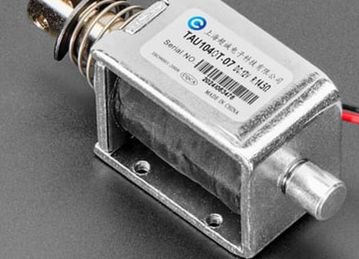
- Read the label on the part. Adafruit’s photograph of its product 413 shows a printed label reading “TAU1040T-07 DC12V”, a maker’s name in Chinese beginning with 上海 (Shanghai), “ISO9001:2008”, a CQC mark and a serial number. The TAU prefix links it to the “TAU-0530B” naming above. The maker could not be identified from the label.
3.4 What a real specification sheet contains
One generic small solenoid does come with a proper specification. SparkFun publishes, as the datasheet for ROB-11015, the bilingual specification sheet of Shenzhen Zonhen Electric Appliances for its part ZHO-0420S-05A4.5. It is worth reading as a template of what every listing should say.5
Table 3 — What a real specification sheet contains
| Item | Zonhen ZHO-0420S-05A4.5 |
|---|---|
| Test conditions | 20 ± 2 °C, 65 ± 5 % RH; force measured with the plunger vertical |
| Rated voltage and usable range | DC 5 V; 5 V ± 5 % |
| Current and power | 1.1 A at 5 V and 20 °C; 5.5 W |
| DC resistance | 4.5 Ω ± 5 % at 20 °C |
| Duty cycle | intermittent, 1 s on, 3 s off |
| Insulation class | B |
| Force | 80 gf minimum at 3 mm stroke, at 5 V |
| Residual magnetism | plunger weight plus a few grams-force (revised in the sheet’s change log) |
| Temperature rise | 65 °C maximum at rated voltage, by the resistance method |
| Life | typically 300,000 cycles, 1 s on, 3 s off |
Four lines in that table answer questions no hobby listing does. The resistance has a tolerance, and it is ±5 %. The duty cycle is a number, here 25 %. The force is given at a stated stroke. And there is a life figure: 300,000 operations at the specified duty. Ledex’s catalogue quotes a standard life of 50,000 to 100,000 operations for its open-frame range, with longer life to special order, and warns that heat “reduces the work output and the life of the unit”.6 A light gun that fires a few thousand shots in an evening can reach 100,000 operations within a few months of regular play. A solenoid is a consumable part, and a gun should let it be changed.
3.5 Where unit-to-unit spread comes from
Light-gun builders often end up owning several power supplies, and the usual explanation is that the solenoids themselves are inconsistent. That question started this dive. The spread is real, and it has identifiable causes. Some are inside the solenoid and some are in the system around it.
Inside the part:
- Coil resistance. Turns count and wire diameter both have tolerances. A careful maker holds ±5 %; nothing is known about the marketplace parts, and two parts sold under one name may be different coils entirely. At fixed voltage, current goes as 1/R and force as (1/R)².
- Residual gap and plunger length. The minimum gap at closure is set by the plunger’s length, the frame’s folding and any non-magnetic shim or plating. Half a millimetre of extra gap matters most exactly where the force curve is steepest.
- Stroke. Set by the plunger’s stop collar or E-clip and the frame. Retailers’ own measurements differ from makers’ datasheets by a factor of two or more.
- Return spring. Preload and rate vary, and a stiffer spring takes force away from the start of the stroke, where the solenoid is weakest.
- Friction. The plunger’s plating and fit in the bobbin, and any side load from the mounting, change how easily it starts.
Around the part:
- Temperature. Copper’s resistance rises by about 0.39 % per kelvin. A coil at 70 °C has about 20 % more resistance than at 20 °C, and at fixed voltage gives correspondingly less current. The kick fades as the gun warms.
- Wiring resistance. A long thin lead in series with a low-resistance coil is a voltage divider. Two metres of two-conductor 24 AWG cable has a loop resistance of roughly a third of an ohm, small against 25 Ω and significant against 4.5 Ω.
- Supply sag and protection. A wall supply rated at a few amps may droop under the pulse, or hit its over-current protection and hiccup.
The lumped model puts rough numbers on each of these, varied one at a time from a nominal 8 Ω coil driven at 24 V for 45 ms:
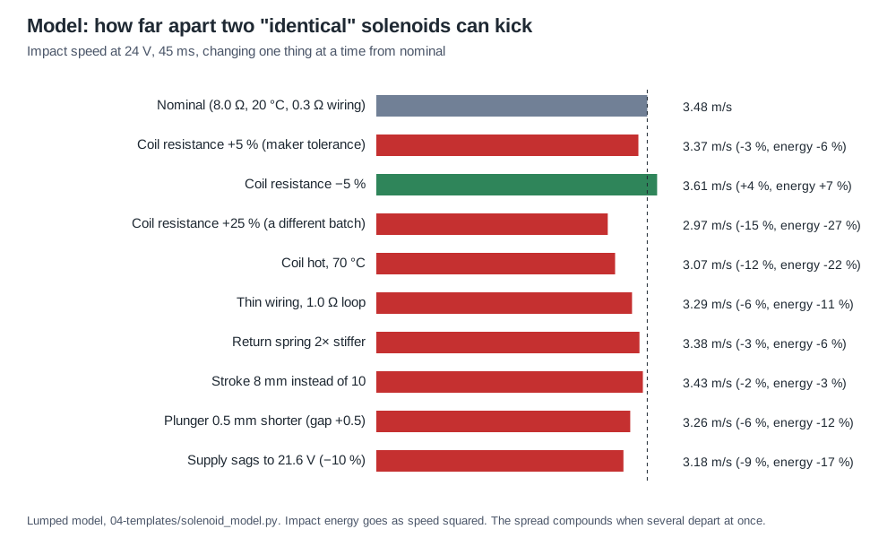
The individual effects are modest, a few percent to twenty-odd percent of impact energy each. They compound: a high-resistance coil, warm, on thin wire, from a sagging supply, can lose half of its kick against a low-resistance coil, cold, on short wire, from a stiff supply. That is a difference the hand notices.
3.6 Why builders end up with a drawer of power supplies
With that list in hand, the drawer of supplies explains itself. A builder who drives a solenoid with a fixed voltage for a fixed time, which is what the open firmware and most DIY boards do, has only two ways to make a weak solenoid kick like a strong one: a longer pulse, which mostly adds heat once the plunger has landed (Volume 4), or a higher voltage. So builders try 12 V, then 24 V, then something in between, solenoid by solenoid. Kit makers specify supplies that worked with the parts they buy, and the specifications disagree with each other (Volume 1). Some of the advice that circulates with those supplies is also mistaken: a retailer’s note that a supply rated for more than 4 A “will overload the recoil solenoid” is wrong as a statement of physics, because a resistive coil draws V/R whatever the supply could deliver.7 There is a defensible reason behind the maker’s own 4 A limit, which is that a small supply’s current limit is the only thing that limits a fault when the driver fails switched on (Volume 7); it is protection, not drive.
There are two engineering ways out of the drawer:
- Calibrate each unit in firmware. Measure each solenoid’s travel time at the chosen supply voltage (Section 3.7) and store a pulse width per gun that ends the pulse just after the plunger lands. This makes the pulse right for each part but does not equalise the force.
- Drive the coil with a regulated current. A current-mode driver sets the ampere-turns directly. Coil resistance, temperature, wiring and supply voltage then drop out of the force, provided the supply has enough headroom to reach the set current quickly. One supply serves every solenoid. Volume 4 develops the theory, and the Reference Electronics dive owns the circuit.
3.7 Characterising a solenoid on the bench
The procedure below measures what a listing should have stated. It needs the instruments of a reasonably equipped electronics lab, all of which this project’s lab has: a four-wire-capable meter, the Digilent Analog Discovery Pro ADP3450 as the oscilloscope (it has no current input, so current is read across a low-side 0.1 Ω shunt; Volume 6), one of the lab’s programmable supplies that can run in constant-current mode (one is controlled over Bluetooth, the rest over USB), the 50 A linear supply for pulse tests, calipers and a kitchen or force scale. Allow about an hour per part. Measure every unit that will go into a gun, not one of a batch.
1. Identify and dimension. Photograph the part and its label. Measure body size, plunger diameter and length, stroke (plunger free against the spring to fully seated), and weigh the plunger and the whole part. Note the spring’s free length and whether it is on the push or pull end.
2. Cold resistance. Leave the part on the bench for an hour so it sits at room temperature. Record that temperature. Measure the coil resistance four-wire, or with a 1 A constant current and a voltage reading, keeping the measurement brief. This is R₂₀ if the room is near 20 °C; correct it with the 0.393 %/K coefficient if not.
3. Inductance, open and closed. Put a 0.1 Ω shunt in series and apply a low voltage step, well below the voltage that moves the plunger, with the plunger held open. On the ADP3450, the current rises as 1 − e^(−t/τ); fit τ and compute L = τ·(R + R_shunt). Repeat with the plunger held seated (clamp it). The ratio of closed to open inductance is a quick measure of how much the gap dominates; in the dive’s model it is about six. An LCR meter at 100 Hz to 1 kHz gives the same small-signal figures.
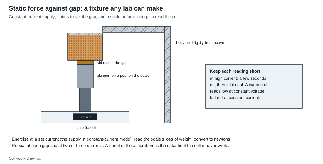
4. Static force against gap. Use the fixture below. Hold the solenoid body rigidly above a scale, stand the plunger on a post on the scale, and set the gap with shims. Run the coil from the supply in constant-current mode at a chosen current, read the drop in the scale’s reading, and convert to newtons. Repeat at gaps of 0.5, 1, 2, 4, 6, 8 and 10 mm and at two or three currents. Keep each reading to a few seconds at high current and let the coil cool between. Constant current makes the result independent of how warm the coil has become.
5. Travel time at the working voltage. Drive the part at the voltage the gun will use, with a pulse long enough to be sure it lands, and capture the coil current through the shunt. The cusp in the current marks the plunger’s arrival (Volume 2, Volume 4). Record the time from turn-on to the cusp, and the time from turn-off until the current reaches zero. Repeat ten times; the spread of arrival times is itself a measure of how consistently the part starts.
6. Heating at the working duty. Fire the part at the pattern the gun will use, for example the firmware’s automatic-fire timing, for 30 seconds. Then stop and immediately measure the resistance again. The average coil temperature rise is ΔT = (R_hot / R_cold − 1) / 0.00393, which is the resistance method the Zonhen sheet uses.5 A thermocouple or TMP36 on the frame will read lower than this, because the winding is hotter than its surroundings; record both, since the firmware’s protection will only ever see the sensor.
7. Kick. Volume 6 describes a rig for measuring the impulse each shot delivers. For a first comparison between parts, the travel time from step 5 at a fixed voltage ranks them well: a faster plunger is carrying more energy into the stop.
3.8 A record sheet for each unit
Table 4 — A record sheet for each unit
| Field | Unit A | Unit B |
|---|---|---|
| Listing name, seller, date bought, price | ||
| Label text | ||
| Body size; plunger diameter × length; stroke | ||
| Plunger mass; total mass | ||
| R at room temperature (state the temperature) | ||
| L open; L closed | ||
| Force at 0.5 / 2 / 5 / 10 mm gap, at current I₁ | ||
| Force at the same gaps, at current I₂ | ||
| Arrival time at working voltage (mean, spread of 10) | ||
| Current-to-zero time after turn-off, with the gun’s clamp | ||
| Resistance after 30 s of automatic fire; computed ΔT | ||
| Frame sensor temperature at the same moment | ||
| Notes: noise, side play, spring condition |
3.9 What could not be verified
- The marketplace prices and specifications of JF-0530B and JF-0826B parts on AliExpress and Amazon. Neither site could be read on 2026-10-18; the listings above are from retailers whose pages could be.
- The maker behind the “JF” and “TAU” prefixes. The TAU1040T label names a Shanghai company that could not be identified. The prefixes are treated as size classes.
- The original maker of the 0826B body. At least two different bodies are sold under the name.
- Resistance spreads within a batch. No published batch measurement was found; the ±5 % figure is Zonhen’s tolerance for one part, not a property of the market.
Sources
Footnotes
-
Probots, “0826B 12V Solenoid 2kg Push-Pull Linear Actuator Motor Electromagnet”, SKU PRO850, https://probots.co.in/0826b-12v-solenoid-2kg-push-pull-linear-actuator-motor-electromagnet.html, read 2026-10-18 (₹999.00 including GST). ↩
-
Sigmanortec, “Electromagnetic piston, JF-0530B, with solenoid, 12V, push-pull”, https://sigmanortec.ro/en/electromagnetic-piston-jf-0530b-with-solenoid-12v-push-pull, read 2026-10-18. ↩ ↩2
-
Adafruit, product pages 413 (“Large Push-Pull Solenoid”), 412 (“Small Push-Pull Solenoid - 12VDC”), 2776 (“Mini Push-Pull Solenoid - 5V”) and 3992 (“Medium Push-Pull Solenoid - 5V or 6V”), https://www.adafruit.com/product/413 and siblings, read 2026-10-18. ↩
-
SparkFun Electronics, “Solenoid - 36V”, ROB-10391, https://www.sparkfun.com/solenoid-36v.html, and “Solenoid - 5V (Small)”, ROB-11015, https://www.sparkfun.com/solenoid-5v-small.html, read 2026-10-18. ↩
-
Shenzhen Zonhen Electric Appliances Co., Ltd., specification ZHO-0420S-05A4.5, rev. B, as published by SparkFun at https://cdn.sparkfun.com/datasheets/Robotics/ZHO-0420S-05A4.5%20SPECIFICATION.pdf, read 2026-10-18. ↩ ↩2
-
Ledex (Saia-Burgess), Ledex® Solenoids, open-frame section H, “Design Considerations” (PDF created 2007-07-20). Copy at https://www.contact-evolution.ch/files/LEDEX_Solenoids_H.pdf, read 2026-10-18. ↩
-
Arcade Renovations, “Ultimarc AimTrak Arcade Light Gun With Recoil - Red”, https://www.arcaderenovations.com/aimtrak-recoil-light-gun-red.html, read 2026-10-18. ↩
Comments (0)