Solenoid Recoil · Volume 2
Solenoid Physics — The Magnetic Circuit, the Force-Stroke Curve and the Voltage That Is Really a Duty Cycle
Why the pull is weak at the start of the stroke and enormous at the end, why one coil can honestly be sold as a 12 V and a 38 V part, and what push, pull and impact arrangements change
Volume 1 showed that every light gun that kicks does it with a solenoid. This volume explains how that solenoid makes force, at the depth an electrical engineer needs to reason about one on the bench. The aim is three results that the rest of the dive depends on. First, the force a solenoid makes depends on the square of its ampere-turns and, roughly, the inverse square of the air gap, so it is weak at the start of the stroke and enormous at the end. Second, a solenoid’s voltage rating is a statement about heat at a duty cycle, not about what the coil can stand. Third, the kick the hand feels is set by how the moving mass stops, not by the force the coil makes on the way.
2.1 The magnetic circuit
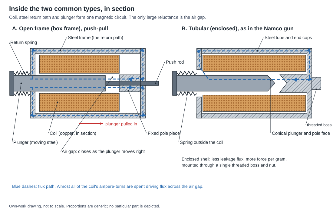
Treat the solenoid as a magnetic circuit. The coil of N turns carrying current i is the source, with a magnetomotive force of N·i ampere-turns. The flux it drives follows a closed loop: along the plunger, across the working air gap into the fixed pole piece, through the frame or tube, and back into the plunger through a second, small radial clearance where the plunger passes through the end plate. Each part of the loop has a reluctance, its length divided by its permeability and cross-section, and the flux is the magnetomotive force divided by the sum.
Steel has a relative permeability in the thousands while it is unsaturated, and the frame and plunger are short and fat, so their reluctance is small. Air has a relative permeability of one. A working gap of a few millimetres therefore dominates the circuit: with the plunger open, nearly all of the N·i is spent pushing flux across the gap. To a first approximation the flux density in the gap is
B ≈ μ₀·N·i / g
where g is the gap length, plus a small allowance for the steel path and the radial clearance, which this dive lumps into an equivalent extra gap. As the plunger moves in and g shrinks, the same current drives more flux. That single fact explains most of what a solenoid does.
2.2 Force from energy: where the pull comes from
The force on the plunger follows from the energy stored in the field. For a magnetically linear device with inductance L that depends on plunger position x, the force at constant current is
F = ½ · i² · dL/dx
and if the gap reluctance dominates, L ≈ μ₀·N²·A / g, where A is the pole area. Differentiating with respect to the gap gives the classic result for a flat-faced plunger:
F ≈ μ₀ · (N·i)² · A / (2·g²)
which can also be written as F = B²·A / (2μ₀), the pressure of the field across the pole face times its area. Two things follow directly. Force goes as the square of the ampere-turns, so twice the current gives four times the force, and twice the voltage on a resistive coil gives four times the force once the current has settled. And force goes as the inverse square of the gap, so the last millimetre of travel produces far more force than the first.
These are textbook relations; Roters’s 1941 treatment of electromagnetic devices is the standard source for them, and every solenoid maker’s catalogue curves are their measured expression.1 They are approximations: fringing flux round the gap, leakage flux that bypasses the gap, and the steel’s own reluctance all modify them. The next two sections show how far the real curves follow the simple law, and where they leave it.
2.3 Why force climbs so steeply at the end of the stroke
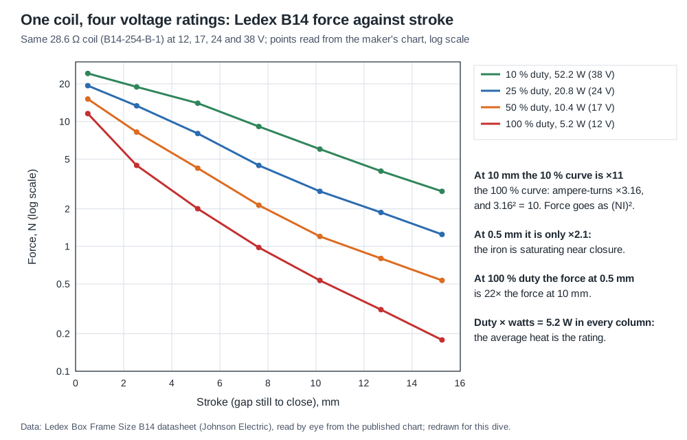
The clearest published illustration found for this dive is the datasheet for the Ledex B14 box-frame solenoid. It gives force against stroke for one coil at four power levels.2 Read off the maker’s chart, the B14 at its continuous rating (5.2 W) pulls about 2.6 lb (11.6 N) with 0.5 mm of gap left to close, about 1.0 lb (4.4 N) at 2.5 mm, 0.45 lb (2.0 N) at 5 mm and 0.12 lb (0.5 N) at 10 mm. The force at 0.5 mm is about 22 times the force at 10 mm.
The same shape appears in the lumped model used throughout this dive, which represents a generic 30 mm open-frame solenoid of the kind sold for hobby use: an 8 Ω coil, a 6 mm plunger, 10 mm of stroke. Its code is in the dive’s 04-templates/solenoid_model.py, and it is a teaching model, not a datasheet. At 12 V it pulls about 0.5 N with the plunger fully out, 1.5 N half-way and about 20 N closed.
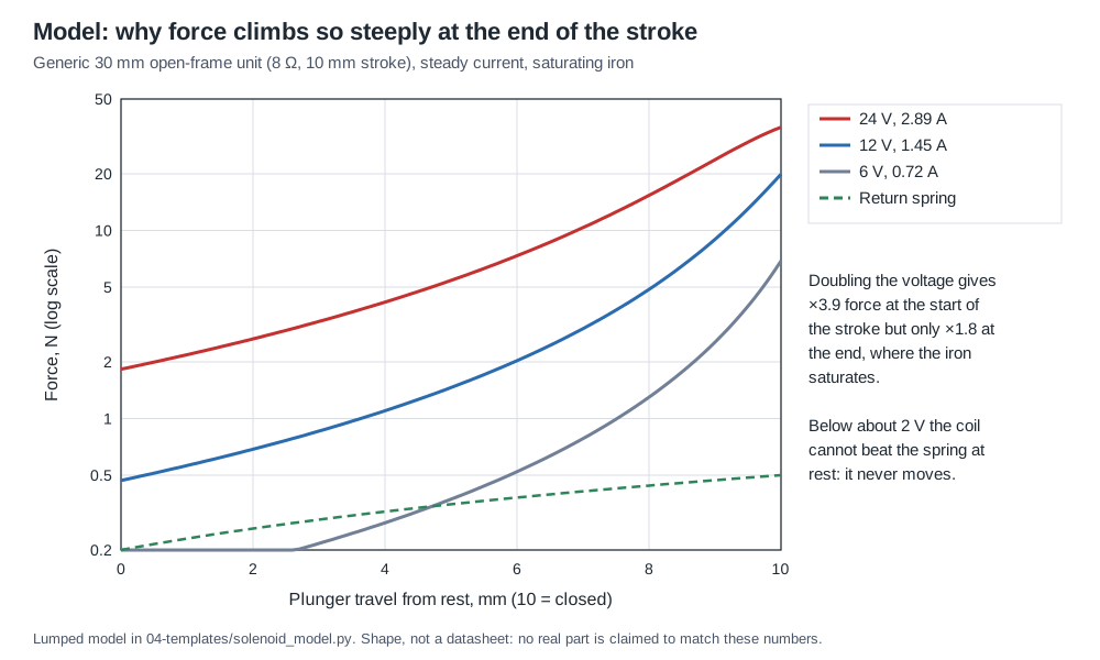
This shape has four consequences for a light gun.
- A solenoid is weakest exactly where it has to start the moving mass. Its starting force must exceed the spring preload and friction with margin, or it will not move at all, and a solenoid that only just starts will start slowly and inconsistently.
- Short-stroke operation is very strong. A unit that is only asked to move 3 mm runs entirely on the steep part of its curve. A unit asked for its full listed stroke spends most of its travel on the shallow part.
- The energy delivered to the moving mass is the area under the curve, and most of that area is in the last few millimetres. Shims that shorten the stroke lose little energy if they shorten it at the open end and a lot if they leave a gap at the closed end.
- A solenoid’s “force” figure is meaningless without a stroke. Listings for the hobby units quote a single number of newtons; Volume 3 shows what that does to anyone trying to compare them.
2.4 Saturation: the ceiling near closure
The inverse-square law would give infinite force at zero gap. Steel prevents it. As the gap closes, the flux density in the plunger and pole rises until the steel saturates at something like 1.5 to 2 T, and beyond that more ampere-turns buy very little more flux. The force then approaches a ceiling set by the pole area: F_max ≈ B_sat²·A / (2μ₀).
The Ledex B14 data show the effect cleanly. At 10 mm of gap, where the circuit is far from saturation, the 10 % duty curve is about 11 times the 100 % curve. The coil’s ampere-turns at those ratings are 2370 and 750, a ratio of 3.16, and 3.16 squared is 10.0: the long-gap force follows (NI)² almost exactly. At 0.5 mm the ratio is only about 2.1.2 Near closure, extra drive mostly becomes heat.
The practical reading for a light gun is that overdriving a solenoid buys force at the start of its stroke, where it is needed, and very little at the end. Volume 4 turns that into a drive strategy: high voltage for a short pulse, ended as soon as the plunger arrives.
2.5 One coil, four voltage ratings
The B14 datasheet contains the single most useful idea in solenoid selection, and the hobby listings never state it. The coil B14-254-B-1 has a resistance of 28.6 Ω at 20 °C and 1791 turns. Ledex rates that one coil at 12 V for 100 % duty, 17 V for 50 %, 24 V for 25 % and 38 V for 10 %.2 The table that goes with it is:
Table 1 — The B14 datasheet contains the single most useful idea in solenoid selection, and the hobby listings never state it. The coil B14-254-B-1 has a resistance of 28.6 Ω at 20 °C and 1791 turns. Ledex rates that one coil at 12 V for 100 % duty, 17 V for 50 %, 24 V for 25 % and 38 V for 10 %.[^b14] The table that goes with it is
| Maximum duty cycle | 100 % | 50 % | 25 % | 10 % |
|---|---|---|---|---|
| Rated voltage, B14-254-B-1 | 12 V | 17 V | 24 V | 38 V |
| Watts at 20 °C | 5.2 | 10.4 | 20.8 | 52.2 |
| Ampere-turns at 20 °C | 750 | 1060 | 1500 | 2370 |
| Maximum on-time, pulsed continuously | unlimited | 100 s | 36 s | 7 s |
| Maximum on-time, single pulse | unlimited | 480 s | 180 s | 45 s |
Multiply each column’s watts by its duty cycle and the answer is 5.2 W every time. The voltage rating is a thermal rating: it is the voltage at which the coil’s average dissipation, at that duty cycle, equals what the coil can shed continuously. The maximum on-time rows add the second constraint, that a single pulse must not heat the coil past its insulation class before the off-time can cool it. Ledex’s catalogue defines duty cycle in the ordinary way, on-time divided by on-plus-off time, and recommends a design safety factor of 1.3 to 1.5 on force; its curves assume 20 °C ambient and no heat sink.3
This is why the light-gun world uses “12 V” solenoids on 24 V supplies and arcade guns ran their coils far above anything continuous. A recoil pulse is short and infrequent: at 45 ms on and 80 ms off, as OpenFIRE’s defaults fire, the duty cycle is 36 %, but a typical game fires in bursts with long pauses between them. The question to ask of any solenoid is not “what voltage is it?” but “what average power can it shed, and how long can one pulse last?” Volume 4 answers it for the parts in use.
2.6 Pole faces: flat against conical
The shape of the plunger tip and pole face reshapes the curve. A flat face gives the steepest curve: weak at long stroke and very strong near closure, with the highest holding force. A conical face, a cone on the plunger seating in a matching recess, puts part of the gap at an angle to the motion. The force along the axis is lower at closure but the gap closes more gradually, so the curve is flatter and the force at long stroke is higher. Ledex offers both on several frames; for its B14M latching variant it quotes a holding force of 9.3 N with a flat face and 5.6 N with a 50° conical face.3
For a recoil striker the trade is clear in principle: a flatter curve gets a heavy mass moving sooner, and the very high force at closure is wasted on a mass that is about to hit a stop anyway. The hobby open-frame parts almost all have flat faces. The Namco tubular unit in the Time Crisis gun, from the manual drawing in Volume 1, has a plain plunger whose face cannot be seen; no claim is made about its shape.
2.7 Open frame against tubular
The two constructions in the figure at the top of this volume make the same magnetic circuit in different packages.
Open frame. A bobbin coil sits in a folded steel frame. In a C frame the steel encloses the coil on one side; in a box frame it encloses it on two. Ledex’s catalogue notes that the box frame “provides slightly higher force output and is more rugged in design”.3 The coil’s other faces are open to the air, which helps cooling, and the steel return path is thin sheet, which saturates early and leaks flux. Almost every cheap hobby solenoid, including the JF-0530B and JF-0826B families and the units Adafruit and SparkFun sell, is an open-frame box frame.
Tubular. The coil sits inside a steel tube closed by end caps, one of which carries the pole piece and usually a threaded boss for mounting. The steel completely surrounds the coil, so leakage is lower, more of the ampere-turns reach the gap, and force per gram is higher; the price is that the coil’s heat must leave through the steel shell. The Namco Time Crisis gun used a tubular unit clamped through a bracket by a 16 mm nut.
For a gun designer the practical differences are mounting and heat. A tubular unit mounts on one threaded boss, concentric with its plunger, which is exactly what a striker running along the bore axis wants. An open-frame unit mounts on tapped holes in its frame and is easier to fit into a printed cradle. Both need their heat to go somewhere other than the plastic shell; Volume 4 deals with that.
2.8 Push, pull and impact
Every solenoid in this dive pulls: the plunger is drawn into the coil. “Push” units are the same device with a rod through the pole piece that pokes out of the far end. The listings’ “push-pull” means only that both ends are available.
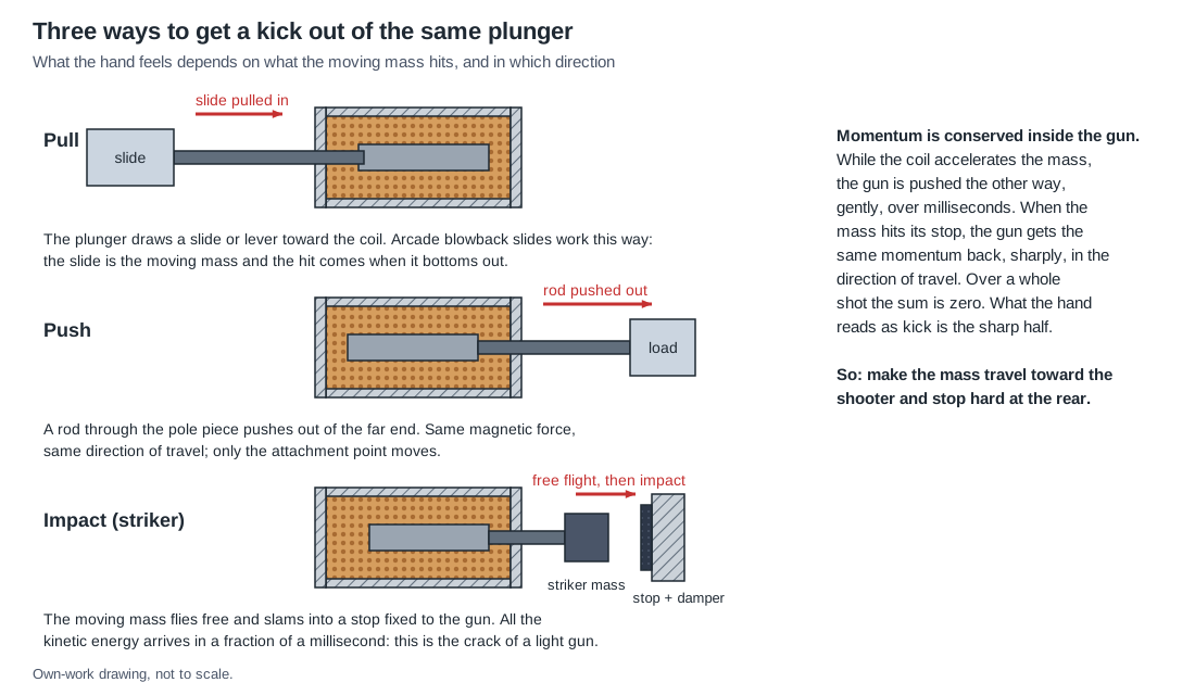
What does change the kick is what the moving mass does at the end of the stroke:
- Pull, driving a slide. The plunger draws a slide or lever; the hit comes when the slide or the plunger bottoms out. The arcade guns’ slides add mass and make the motion visible.
- Push, driving a load. The rod drives something outside the coil, such as a hammer (the Blamcon Ace of Spades) or a moving ejection port cover (the subject of the Moving Ejection Port dive).
- Impact. The moving mass is a free striker that flies and hits a stop. All of its kinetic energy arrives at the stop in a fraction of a millisecond. This is what gives a light gun its crack, and it is where Volume 5 starts.
2.9 Force, impulse and what the hand feels
It is tempting to rate a recoil solenoid by its force. The force the coil makes on the plunger is not what reaches the hand. While the coil accelerates the plunger, the reaction pushes the coil, and therefore the gun, the other way, gently, over several milliseconds. When the plunger hits its stop it gives the gun the same momentum back, in the direction it was travelling, in a fraction of a millisecond. Over a complete shot, including the return stroke, the momentum exchanged sums to zero: nothing leaves the gun. What the hand registers as kick is the sharp half of that exchange, so the useful measures of a recoil solenoid are:
- the momentum the moving mass carries into the stop, p = m·v;
- the direction of that momentum relative to the shooter;
- the sharpness of the stop, which sets the peak force and therefore how hard the tap feels for the same momentum;
- the repeatability of all three from shot to shot.
Energy and momentum trade through the moving mass. For a given energy E delivered to the striker, its momentum is √(2·m·E), so a heavier striker carries more momentum for the same energy and the same coil. That is the reason the arcade guns throw a whole slide rather than a bare plunger, and it is quantified in Volume 5.
2.10 The coil is not a resistor
The electrical side of the same physics is the subject of Volume 4, but three facts belong here because they come straight from L(x).
- The inductance changes with position. In the lumped model the small-signal inductance is about 7 mH with the plunger out and 44 mH with it in, a factor of six. The electrical time constant L/R changes by the same factor.
- A moving plunger generates a back-EMF. The term i·(dL/dx)·v appears in the coil’s voltage equation, so while the plunger is moving fast toward closure the current falls. On a current trace the plunger’s arrival shows as a sharp minimum, a cusp. Volume 6 uses that cusp as a free position sensor.
- There is no inrush. An inductive load’s current starts at zero and rises toward V/R. Some retailers’ pages describe current “rushing” into a solenoid to “charge up” the magnet at turn-on. It does not; the largest current a DC solenoid draws from a fixed voltage is its steady-state V/R, reached only after the plunger has landed.
2.11 Holding force and residual magnetism
Two figures on the better listings describe the closed end of the curve. Holding or retentive force is the pull with the plunger seated and the coil energised. Adafruit gives its small 12 V push-pull solenoid a starting force of 0.5 N and a retentive force of 5.0 N: a ten-to-one ratio that is the force-stroke curve in two numbers.4 Residual magnetism is the force that remains when the coil is switched off with the plunger seated; the Zonhen specification sheet for a small 5 V solenoid specifies it as no more than the plunger’s own weight plus a few grams-force.5 For a recoil mechanism residual force matters only if it is enough to hold the plunger against a weak return spring, which would delay or prevent the return stroke; in a well-designed unit it is not.
2.12 What could not be verified
- No force-stroke curve was found for any of the generic hobby solenoids (JF-0530B, JF-0826B and similar). The curves in this volume are the Ledex B14’s and the dive’s own model’s.
- The model’s parameters (turns, pole area, steel equivalent gap, saturation) are chosen to resemble a 30 mm open-frame unit and are not measurements of one. Volume 3 shows how to measure a real one.
- The pole-face shape of the Namco ST-0860A2 plunger was not visible in any source found.
Sources
Footnotes
-
Herbert C. Roters, Electromagnetic Devices, John Wiley & Sons, 1941: the standard engineering treatment of solenoid and electromagnet force from the energy of the magnetic field. ↩
-
Ledex (Johnson Electric), Ledex® Box Frame Size B14 datasheet (PDF created 2014-03-26), specifications, performance table, coil data and force-stroke chart. Copy at https://media.e-sonic.com/productfiles/mf-jon/openframe_b14.pdf, read 2026-10-18. Chart values read by eye at 220 dpi and stated to two significant figures. ↩ ↩2 ↩3
-
Ledex (Saia-Burgess), Ledex® Solenoids, open-frame section H, “Design Considerations” (construction, life, performance curves, duty cycle) and the B14M latching data (PDF created 2007-07-20). Copy at https://www.contact-evolution.ch/files/LEDEX_Solenoids_H.pdf, read 2026-10-18. ↩ ↩2 ↩3
-
Adafruit, “Small Push-Pull Solenoid - 12VDC”, product 412, https://www.adafruit.com/product/412, technical details, read 2026-10-18. ↩
-
Shenzhen Zonhen Electric Appliances Co., Ltd., specification ZHO-0420S-05A4.5, rev. B, §5-2 (residual magnetism), as published by SparkFun at https://cdn.sparkfun.com/datasheets/Robotics/ZHO-0420S-05A4.5%20SPECIFICATION.pdf, read 2026-10-18. ↩
Comments (0)