Arcade Hardware · Volume 5
Cabinet I/O, Power and Recoil — Coin and Start, the Cabinet's 24 V, Grounding, and Getting the Game's Recoil Back to the Gun
What a gun cabinet supplies and switches (Sega's Cosel 12 V and 24 V supplies, Namco's +24 V solenoid feed, the fuses per gun), what goes dead when the I/O board is emulated, three ways to turn the game's solenoid command into a kick at the project's gun and why two of them lose, and where the converter, the gun's own 24 V brick and the GX socket go in a real cabinet
5.1 What a gun cabinet supplies
The manuals give the rails and the parts behind them.
Sega, Ghost Squad (Chihiro, 2004). The electrical assembly lists two Cosel switching supplies, an “SW REGU LCA30S-12” for 12 V and an “SW REGU LCA75S-24” for 24 V, a separate “SW REGU FOR CHIHIRO” for the game board, a solid-state relay board (“SSR BD 2 AC 2A”), a stereo amplifier and the gun-sense board.1 Cosel’s own product page gives the LCA75S-24 as 24 V at 3.2 A, 76.8 W, with an input of 85 to 132 V AC (or 110 to 170 V DC).2 That input range explains another line in the parts list: for 200-volt areas the cabinet carries a “PWR XFMR 200-240V 100V 10A” in its own transformer assembly, so the electronics always see about 100 V.1 The fuse panel separates the gun circuits: “There are 200mA (for the sensors) and 2A (for the solenoids) fuses”, FUSE1 and FUSE3 for the player 1 and player 2 gun sensors, FUSE2 and FUSE4 for the two gun solenoids.1 The 24 V supply therefore exists to fire the gun solenoids, at up to 2 A per gun.
Sega NAOMI. The game board itself takes +3.3 V, +5 V and +12 V on JST VL connectors (CN1, CN2).3 The solenoid and lamp voltages are the cabinet’s business, not the board’s.
Namco, Time Crisis 4 (System 256, 2006). The schematic’s power connector carries +12 V, +5 V and +24 V, and each gun’s connector carries TRIGGER, GND, +24 V and SOL: the solenoid is fed +24 V and switched on its SOL return.4 Point Blank (1994) had the same +24 V solenoid feed on its harness (Arcade Light Guns Vol 2).
The project’s recoil rail is “24 V class, 18–28 V working” (decision D14). That is the arcade’s own solenoid voltage, which is not a coincidence: Solenoid Recoil Vol 1 traces the home guns’ recoil to these cabinets. It makes the cabinet’s 24 V tempting as the gun’s supply. Section 5.6 explains why the gun should still bring its own.
5.2 What goes dead when the I/O is emulated
When OpenJVS replaces the cabinet’s I/O board (Volume 3), everything that was wired to that board stops being read or driven, because the board is no longer on the JVS cable:
Table 1 — When OpenJVS replaces the cabinet's I/O board (Volume 3), everything that was wired to that board stops being read or driven, because the board is no longer on the JVS cable
| Wired to the real I/O | Under OpenJVS |
|---|---|
| Original guns’ triggers and buttons; the gun-sense board | Replaced by the project’s gun, read over USB |
| Coin switches, start buttons, test and service | Not read unless they reach the Pi as a Linux input device (5.3) |
| Pedals (Time Crisis), action buttons | Same |
| Gun solenoids and gun motors (output writes) | Not driven: OpenJVS discards output writes (Volume 3, 3.9) |
| Start lamps, coin meters, cabinet lighting on I/O outputs | Same |
That is the price of emulating the I/O instead of feeding it. Nothing is damaged; the cabinet’s original controls are simply disconnected from the game.
5.3 Coin, start, test and service
For a home cabinet the coin mechanism is rarely wanted. The board’s test menu carries the coin settings (the NAOMI and Lindbergh system menus both list “COIN ASSIGNMENTS”),35 where free play is normally found, and that menu is reached through OpenJVS’s virtual Test button. The gun itself supplies Start (its keyboard device, Volume 3, 3.6). Test and service still need buttons, at least for calibration.
Two ways to get the cabinet’s own buttons back:
- A USB keyboard encoder on the Pi. Any encoder that appears as a keyboard is an input device OpenJVS reads; a device file maps its keys to
CONTROLLER_BUTTON_TEST,CONTROLLER_BUTTON_SERVICE,CONTROLLER_BUTTON_COINand the pedal. The cabinet’s microswitches then wire to the encoder instead of the I/O. A Pico running a keyboard sketch does the job for a few dollars and keeps to the project’s microcontroller; a commercial encoder such as Ultimarc’s I-PAC does it out of the box. - The pedal on the gun. The project’s gun has spare inputs (Controls and Inputs); a Time Crisis pedal wired to one and mapped like any button needs no extra hardware, at the cost of a pedal lead running to the gun’s cable.
Coin meters and lamps driven by the I/O stay dark unless the output forwarding in 5.5 also drives a few Pi GPIOs through MOSFETs; that is an optional extension, not part of the first build.
5.4 Recoil: three routes, one worth taking
The game decides when a cabinet gun kicks: a pulse per shot, a burst for a machine gun, a long hold for Time Crisis’s slide. The project’s gun has a regulated solenoid stage of its own (D13), sequenced against the ejection-port stage (D16), and accepts game-driven recoil as commands on its serial port: F0x2x<n> queues n pulses at the gun’s own timings, F0x1/F0x0 turn it on and off, with a forced shut-off after 2000 ms (Open-Source Firmware Vol 6). The question is only how the game’s command gets to that port.
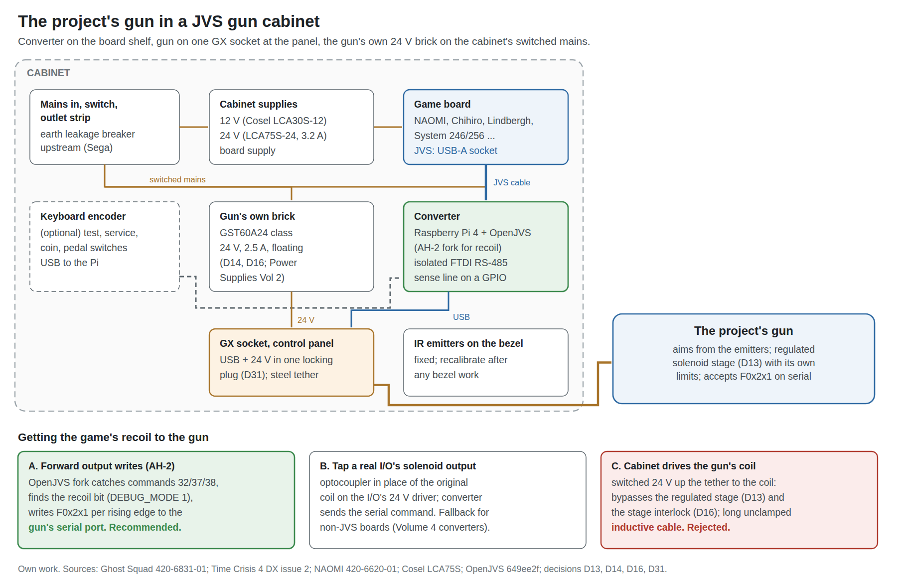
Table 2 — 5.4 Recoil: three routes, one worth taking
| Route | How | Verdict |
|---|---|---|
| A. Forward the game’s output writes (AH-2) | A fork of OpenJVS catches the output-write commands that stock OpenJVS discards (32, 37, 38), finds the recoil bit for each player, and writes F0x2x1 (or the hold form) to that gun’s serial port | Recommended. All in software, uses the gun’s own drive and protections, works on every JVS board OpenJVS supports |
| B. Tap a real I/O’s solenoid output | Where the cabinet’s real I/O stays (positional or optical boards fed by Volume 4’s converters, or a cabinet where the real I/O is kept for other reasons), replace each gun solenoid on the I/O’s driver output with an optocoupler input to the converter, which then sends the serial command | Fallback for boards with no JVS I/O to emulate. Keeps the gun’s regulated drive. Needs one optocoupler channel per gun and a resistor sized for the cabinet’s 24 V |
| C. Let the cabinet drive the gun’s coil | Run the cabinet’s switched 24 V solenoid line up the tether to a coil in the gun | Rejected. Bypasses the regulated current stage (D13) and the stage interlock (D16), puts an unregulated, unclamped inductive load on a long cable, and depends on a cabinet driver designed for a different coil |
Route C is how the original cabinets did it, and the reason the project does not is in Solenoid Recoil Vol 4: a regulated stage gives the same kick regardless of coil, temperature, wiring and supply, and a cabinet driver gives whatever its coil and cable allow.
5.5 Forwarding the game’s recoil (AH-2) in detail
The fork’s job is small and specific:
- Find the bits. Which output bit fires which gun’s solenoid differs per game, and none of the manuals read for this dive tabulates it. OpenJVS already has the tool to find out:
DEBUG_MODE 1“will show the JVS outputs”.6 Fire each player’s gun in the game’s output test (every Sega and Namco gun game has one: Time Crisis 4’s “SOLENOID TEST”, HOTD4’s “GUN MOTOR1/2” in its output test) and read which bit moves.45 Record the bit per game in the game profile. - Turn edges into commands. On the recoil bit’s rising edge, write
F0x2x1to that player’s gun: one pulse at the gun’s own pulse length, whatever the game’s timing. For games that hold the bit high for a long action (Time Crisis’s slide stays back while the output is high, per Miceli’s description of the TSS-I/O7), the same single pulse is the safe translation; a machine gun that toggles the bit per bullet gets a pulse per toggle. This is the rule PC (Windows) proposes for emulators (PW-3: pulses at the gun’s timing, never holds), carried over unchanged. - Open the right port. Each gun’s serial port has a stable name under
/dev/serial/by-id/that embeds its product name,FIRECon P1orP2(Linux and Retro Distros Vol 1). The fork opens the port matching the player’s device and sendsSfirst to put the gun in serial mode. - Leave the gun in charge. The gun keeps its own limits: pulse length, maximum rate, the 2000 ms forced shut-off and the D16 interlock all live in the firmware, so a game that misbehaves cannot overheat the coil.
The same mechanism serves HOTD4’s gun motor if the gun has one (Motors and Rumble), with a different serial command. The fork is GPL-3.0 like OpenJVS; for the private build that changes nothing, and for any kit it is a separate program from the gun’s firmware (Licensing, IP and Kits).
5.6 Powering the gun: its own brick, not the cabinet’s 24 V
The gun needs its 24 V rail at the GX connector (decision D31: one locking GX connector carrying USB and 24 V), sized for one solenoid stage at a time (D16), which Power Supplies Vol 2 meets with a Mean Well GST60A24-class brick (24 V, 2.5 A, floating output).
The cabinet’s 24 V would carry it electrically: Sega’s LCA75S-24 gives 3.2 A,2 and with the original solenoids disconnected it has nothing else to do in a gun cabinet. It is still the wrong source, for four reasons:
- Unknown remaining load. The manuals show the 24 V feeding the gun solenoids, but not whether anything else in a given cabinet (a seat shaker, a motor, a light) shares it.
- Grounding. The cabinet’s supplies share the cabinet’s ground and mains earth. The brick’s output floats (Power Supplies Vol 2); taking 24 V from the cabinet joins the gun’s ground to the cabinet’s through the power lead as well as through any data path.
- Age. The cabinet supplies are twenty years old or more, with electrolytic capacitors of the same age; a new brick removes them from the gun’s failure modes.
- Portability. A gun that brings its own brick works in the cabinet, on the desk and at the PC with the same lead and the same behaviour, and every bench result carries over.
So the brick goes inside the cabinet, plugged into the cabinet’s switched mains outlet strip so that the cabinet’s power switch turns the gun off with everything else, and its lead runs to the GX socket on the control panel.
5.7 Grounding and isolation
Four ground systems meet in a converted cabinet: the cabinet’s (mains earth, the game board, the CRT chassis if there is one), the converter’s (the Pi and its supply), the gun’s (the brick’s floating output) and, through USB, the converter’s and the gun’s together. Two choices keep them from forming loops:
- Isolate the RS-485 link, with the isolated FTDI adapter of Volume 3 (or, for the positional converter, the ISO1540 of Volume 4). The converter and gun then touch the cabinet only through the isolator’s barrier.
- Keep the gun’s brick floating and do not take 24 V from the cabinet (5.6).
The metal of the gun is a separate matter: the arcade manuals bond metal guns to the cabinet’s safety earth, and Arcade Light Guns Vol 6 quotes the reminders. The project’s printed gun has no exposed metal tied to its circuit; a machined aluminium build (MP7 Machined Aluminum) would need its own answer.
5.8 Where everything goes
Table 3 — 5.8 Where everything goes
| Item | Where | Connects to |
|---|---|---|
| Raspberry Pi 4 + isolated FTDI RS-485 adapter (or OpenJVS HAT) | On the cabinet’s board shelf beside the game board | The game board’s JVS cable (USB-A at the board); sense line to a Pi GPIO; Pi’s own 5 V supply from the cabinet’s switched mains |
| Keyboard encoder (optional) | Behind the control panel | Test, service, coin and pedal switches; USB to the Pi |
| GX panel socket | Control panel, where the original gun cable entered | USB to the Pi; 24 V from the brick |
| Gun’s 24 V brick (GST60A24 class) | Cabinet floor, on the switched mains strip | GX socket |
| IR emitters | Bezel or monitor surround, as close to the picture’s edges as the bezel allows (IR Point Tracking Vol 3) | Their own supply; a cabinet’s 12 V is suitable if the emitter design is 12 V |
| Gun tether | From the panel to the gun | A steel safety cable beside the electrical lead, as the cabinets used (Point Blank lists a “gun chain”, Arcade Light Guns Vol 2), so that the GX lead never carries the gun’s weight |
5.9 Safety
The cabinet manuals’ warnings stand and are collected in Arcade Light Guns Vol 6: CRT high voltage after power-off, weight, interlocks, earth. Ghost Squad’s manual adds that the cabinet “does not incorporate the Earth Leakage Breaker” and must be fed from a supply that has one.1 Two points are particular to a conversion:
- Work on the converter only with the cabinet unplugged, not merely switched off: the mains strip, the transformer (in 200-volt regions) and the supplies are live up to the switch.
- Never plug a JVS cable into a USB port, or a USB device into a JVS socket (Volume 2). The connectors fit and the voltages do not.
5.10 Why this, and why not the others
Table 4 — 5.10 Why this, and why not the others
| Choice | Pick | Rejected, and why |
|---|---|---|
| Recoil path on JVS boards | AH-2: forward output writes to the gun’s serial port as pulses | Tapping a real I/O (needs the real I/O, which OpenJVS replaces); cabinet drive of the gun’s coil (bypasses D13 and D16) |
| Recoil path on non-JVS boards | Optocoupler on the I/O’s solenoid output into the converter | Cabinet drive of the gun’s coil (same reasons) |
| Gun power | Own GST60A24-class brick on the cabinet’s switched mains | Cabinet’s 24 V: electrically adequate, but unknown sharing, joins grounds, aged, and makes the gun cabinet-specific |
| Cabinet buttons | Free play plus the gun’s Start; a keyboard encoder for test, service, coin and pedal | Rewiring the original I/O as a second JVS node: untested with OpenJVS |
| Ground | Isolated RS-485 adapter, floating brick | Non-isolated adapter: works, but joins the converter and gun to the cabinet ground |
5.11 What could not be verified
- Which output bit drives each gun’s solenoid in each game; to be found with
DEBUG_MODE 1per game. - Whether OpenJVS can share a JVS bus with a real I/O board downstream (its data structures allow chained emulated I/Os; a real one was not examined).
- The current status and stock of Cosel’s LCA75S (a search summary lists it as obsolete; Cosel’s own page was not checked for that).
- What else, if anything, shares the 24 V rail in each cabinet model.
- The optocoupler input resistor and part for route B; a sketch only, to be sized against the cabinet’s actual driver and voltage.
Sources
Footnotes
-
Sega, Ghost Squad Deluxe owner’s manual, 420-6831-01, 1st printing November 2004: earth leakage breaker warning (safety precautions), fuses (p. 124), ASSY ELEC CTF-4100, ASSY MAIN BD and ASSY XFMR 200V AREA CTF-4300 parts lists (pp. 177–182). Central Library text
sega-ghost-squad-arcade-owners-manual— read 2026-10-24. ↩ ↩2 ↩3 ↩4 -
Cosel, LCA75S product page (captured as a PDF titled with the coselusa.com product URL, created 28 January 2005, modified 23 December 2008, hosted by RS Components): model table, LCA75S-24 24 V 3.2 A 76.8 W, input AC 85–132 V or DC 110–170 V, https://assets.rs-online.com/v1698861246/Datasheets/c6a2a8a0b19f22722e224a318f110859.pdf — read 2026-10-24. ↩ ↩2
-
Sega Enterprises, NAOMI Service Manual, 420-6620-01, 1st printing February 2001, §2-2 (CN1, CN2), Internet Archive
manualzilla-id-6037988— read 2026-10-24. ↩ ↩2 -
Namco, Time Crisis 4 DX operator’s manual, issue 2, part no. 90500167: schematics (gun connector, power connector) and I/O test (SOLENOID TEST), central Library text
namco-time-crisis-4-dx-manual-issue-2-arcade— read 2026-10-24. ↩ ↩2 -
Sega, The House of the Dead 4 owner’s manual (2005), OUTPUT TEST, Internet Archive
ArcadeGameManualHod4-manual— read 2026-10-24. ↩ ↩2 -
OpenJVS project,
docs/openjvs/config(“DEBUG_MODE 1 - This will show the JVS outputs”), commit 649ee2f — read 2026-10-24. ↩ -
Ryan Miceli, “Light Gun Hacking Part 1: Using Namco light guns in Unity”, icode4.coffee, 27 October 2022, https://icode4.coffee/?p=655 — read 2026-10-24. ↩
Comments (0)