Arcade Hardware · Volume 2
JAMMA and JVS — The Two Wiring Standards, the JVS Packet, the Sense Line, and How Sega's and Namco's Guns Reach the Game Board
Why a JAMMA edge connector has no gun on it; what JVS actually puts on its USB-shaped cable (RS-485 at 115,200 baud and a sense line, not USB); the commands a game board sends and the two ways a gun's position comes back; and what the I/O boards of Sega's and Namco's gun cabinets report about themselves
2.1 JAMMA: one edge connector, no gun
A JAMMA board plugs into the cabinet through a single 56-way, 0.156-inch-pitch edge connector carrying +5 V logic power, +12 V for sound, analogue RGB with negative composite sync, one speaker, coin, service, test and tilt, and two players’ joysticks with three buttons and a start button each.1 That was enough for a fighting game or a shooter with a stick, and it is why JAMMA cabinets were interchangeable.
A gun needs signals the edge connector never defined. An optical gun needs its sensor output (and, on boards that put the timing in a separate board, the video sync); a positional gun needs two analogue voltages; a recoil gun needs a solenoid drive at a voltage JAMMA does not supply. Every gun game of the JAMMA era therefore brought its own extra connectors. Arcade Light Guns Vol 1 reads the Operation Wolf gun wiring (a six-pin connector with SENSOR OUT, ±12 V, ground and two motor leads) and Vol 2 the Point Blank harness (six wires per gun on J16, a separate position PCB fed with C.SYNC). Those are the connections a converter for a JAMMA-era gun board must imitate (Volume 4); the edge connector itself carries nothing for the gun.
2.2 JVS: an I/O board on a cable that is not USB
JAMMA’s second standard, the JAMMA Video Standard (first edition 1996; second edition 17 July 1997; third edition 31 May 2000, according to the JAMMA history summaries1), took the controls off the game board. A JVS cabinet has a separate I/O board that reads the switches, coin mechanisms and analogue controls and drives the lamps and solenoids; the game board asks it for inputs over a serial link and tells it what to drive.
That link uses USB connectors and USB cables, and it is not USB:
Table 1 — That link uses USB connectors and USB cables, and it is not USB
| Item | What it is | Source |
|---|---|---|
| Connector at the game board | USB Series A (“CN5: STANDARD I/O (SERIES A TYPE) Connected to I/O BD via. USB Cable”) | NAOMI service manual2 |
| Connector at the I/O board | USB Type B; the cabinet cable is “CABLE JVS TYPE A-B 100CM” | OpenJVS IO manual; Ghost Squad parts list34 |
| USB pin 1 (VBUS) | Sense line | OpenJVS IO manual; openjvs wiki35 |
| USB pins 2 and 3 (D−, D+) | RS-485 B and A | same |
| USB pin 4 | Ground | same |
| Signalling | RS-485, 115,200 baud, 1 start, 8 data, 1 stop bit, idle at mark | openjvs wiki (from machine translations of the 3rd edition)5 |
The consequence is printed in capitals in the OpenJVS IO manual: “DO NOT CONNECT TO A USB PORT FOR THIS MIGHT DAMAGE JVS-IO BOARD OR THE USB PORT.”3 A JVS cable plugged into a PC does nothing useful and may harm one end; a USB light gun plugged into a JVS socket does the same. The encyclopaedia summary puts it plainly: JVS “is incompatible with USB devices because it does not use the USB signaling standard and protocol.”1
I/O boards can be chained. Sega’s Ghost Squad manual describes the test screen for “2 or more I/O BOARDS” and notes that “The lower the NODE number, the further away the node is from the Chihiro.”4
2.3 The packet
Every message on the bus has the same frame, described in the openjvs wiki and implemented in OpenJVS’s jvs.c:56
Table 2 — 2.3 The packet
| Byte | Meaning |
|---|---|
E0 | Sync. Marks the start of a packet |
| Address | Destination node. The game board (bus master) is 00; I/O boards get 01 upwards; FF is broadcast |
| Length | Number of data bytes plus the checksum byte |
| Data… | One or more commands and their arguments (master to I/O), or a status byte and per-command reports (I/O to master) |
| Sum | Checksum: the 8-bit sum of the address, length and data bytes (OpenJVS’s readPacket() accumulates exactly those) |
Because E0 means “start of packet”, a data byte of E0 is sent as D0 DF, and a data byte of D0 as D0 CF.5 The reply starts with a status byte (01 success, 02 unsupported command, 03 checksum failure, 04 overflow) and then a report byte per command (01 success, 02 parameter error, 04 busy).56
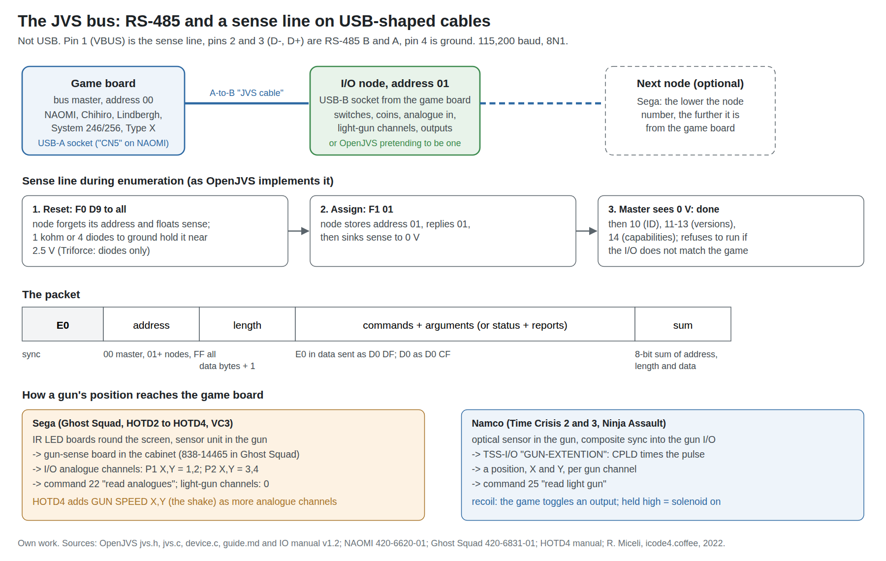
2.4 The sense line and addressing
The sense line is how the game board learns how many I/O boards are on the chain and gives each an address. No translation of the standard’s own wording was found; the behaviour below is what OpenJVS implements in its source and what its guide asks the builder to wire.
- After a reset (command
F0 D9, broadcast), every node forgets its address. OpenJVS then floats its sense output (setSenseLine(0)in theCMD_RESEThandler).6 - The builder must wire the floating line to ground through “a 1KOhm resistor or 4 signal diodes”, whose purpose “is to create a 2.5 volt drop”; the guide warns that “A 1KOhm resistor will not work with the Triforce system, please use the 4 signal diodes for this purpose.”7 The OpenJVS HAT does this on the board, and the four diodes are visible on it (Volume 3).
- When the master assigns an address (command
F1with the address), OpenJVS stores it and, once addressed, sinks the sense line to 0 V (setSenseLine(1)).6
So, as OpenJVS implements it, the line sits at about 2.5 V while an unaddressed node is present and at 0 V once that node has an address. Four forward-biased signal diodes in series clamp the line at about 2.5 V only if the master pulls it up, through a resistance, from something higher; the forum translation says 5 V. That figure was not found in any document read. A forum-posted machine translation of the procedure (reached only through a search summary, because the forum refuses automated reading) describes the master assigning addresses one by one until the sense line reads 0 V; it is consistent with the OpenJVS code but is not treated here as a source.
OpenJVS’s compatibility table shows which boards insist on the sense line: NAOMI 1, System 246 and exA-Arcadia work without it; NAOMI 2, Triforce, Chihiro, Lindbergh, System 23, System 256 and Taito Type X+ and X2 need it; RingEdge and RingEdge 2 “Require JVS Hat”, the board with the proper sense-line levels.7
2.5 The commands a gun game uses
The command codes, as named in OpenJVS’s jvs.h:6
Table 3 — 2.5 The commands a gun game uses
| Code | Command | Used by a gun game for |
|---|---|---|
F0 D9 | Reset (broadcast) | Start of enumeration |
F1 nn | Assign address | Enumeration |
10 | Request ID string | The board identifies its I/O (2.8) |
11, 12, 13 | Command, JVS and comms versions | Same |
14 | Capabilities | The I/O lists what it has: players and switches, coin slots, analogue inputs, light-gun channels, outputs (2.8) |
20 | Read switches | Trigger, buttons, start, test, service |
21 | Read coins | Coin counters |
22 | Read analogues | Sega gun position (2.6), shake sensor (HOTD4) |
25 | Read light gun | Namco gun position (2.7) |
32 | Write general-purpose outputs | Recoil solenoids, gun motors, start lamps |
37, 38 | Write one output byte or bit | Same |
70 | Namco-specific | Namco I/O extras |
The capability codes that matter here are 03 (analogue inputs, with channel count and bits), 06 (light-gun channels, with X and Y bits) and 12 (general-purpose outputs). A game board reads the capability list at boot and, if it does not match the game’s needs, refuses to run: Primeval Hunt’s manual lists “JVS I/O board does not fulfill the game spec.”8 This is why an I/O emulator must present itself as the I/O the game was shipped with, not as a generic one (Volume 3).
Analogue reports are 16 bits per channel, big-endian; a 10-bit converter’s value is left-aligned in the 16 bits unless the I/O is one that right-aligns (OpenJVS carries a RIGHT_ALIGN_BITS flag per emulated board for exactly that).6 Sega’s test screens show the result: the JVS input test displays each analogue channel as “0000” to “FFFF”.4
2.6 Sega: the gun-sense board and the analogue channels
Sega’s own manuals show where a Sega gun’s position enters the game board, and it is not where one might expect.
The Ghost Squad (Chihiro, 2004) JVS test screen reports the cabinet’s I/O board as “I/O BD JVS”: two players of 13 switch bits, two coin slots, “ANALOG 8 CH”, “SCREEN X:0 Y:0 CH:0” and “DRIVER OUT 6 CH”.4 SCREEN is the JVS light-gun capability, and it has zero channels. Yet the game’s own input test shows “GUN-X: The current X-coordinate of the controller’s target location. (range: 00-FF)”, “GUN-Y” likewise, and “SCREEN: If the controller is facing the screen, this will be IN, otherwise it is OUT.”4 With no light-gun channel on the I/O, the gun’s X and Y must be arriving on the I/O’s analogue channels, and the on-screen/off-screen state on a switch input. OpenJVS’s game profiles agree independently: its generic-shooting profile, used for The House of the Dead 2, 3, Virtua Cop 3 and Ghost Squad, maps player 1’s aim to analogue channels 1 and 2 and player 2’s to 3 and 4.6
What produces those analogue values is a board in the cabinet. The Ghost Squad electrical assembly lists “IC BD GUN SENCE NEW EDIT DX” (838-14465) beside “I/O CONTROL BD 2 W/O 232C DOG” (837-13844-02), with harnesses “WH SENSOR LED ELEC”, “WH SENSOR CONT ELEC” and “WH SENSOR FREQ ELEC”, the last being the interference jumper that alternate cabinets in a row leave off.4 The gun’s sensor unit (JPT-2030) and the LED boards round the screen are described in Arcade Light Guns Vol 4; the gun-sense board turns what the sensor sees into a position and presents it to the I/O. The manuals do not say whether it feeds the I/O as analogue voltages or by another route, so that detail is unverified; what the game board receives is analogue JVS channels either way.
The House of the Dead 4 (Lindbergh, 2005) adds two more channels per gun. Its input test lists “GUN SPEED X” and “GUN SPEED Y” (resting at 7f) beside “GUN X”, “GUN Y” and “SCREEN IN”, and its adjustment screen asks the operator to “PLEASE SHAKE THE PLAYER1 GUN”.9 The shake that reloads and frees the player from grabs is therefore two analogue channels too, and its output test lists “GUN MOTOR1” and “GUN MOTOR2”.9 Volume 3 takes up what that means for an emulated I/O.
The same Ghost Squad manual lists the games that “employ a same or similar type of sensor” and may interfere when installed side by side: The House of the Dead 2, Death Crimson, The Lost World, Brave Fire Fighters, Samba de Amigo, Confidential Mission, Shakatto Tambourine, Lupin the 3rd The Shooting, The Maze of the Kings, The House of the Dead 3, Virtua Cop 3 and Ghost Squad.4 By Sega’s own account, then, its infrared gun-sense system goes back at least to The Lost World (1997) and The House of the Dead 2 (1998), not only to the 2002 House of the Dead III manual that Arcade Light Guns Vol 4 found as its earliest. That matters in Volume 6: every game on that list is display-independent.
2.7 Namco: a gun I/O board that does the timing
Namco took the other branch of the JVS standard. Its gun cabinets use a gun I/O board that reports through the light-gun command (25).
Ryan Miceli’s investigation of a Time Crisis 3 cabinet (System 246, 2022) is the clearest primary description. The gun’s board reports itself over JVS as “namco ltd.;TSS-I/O;Ver2.11;GUN-EXTENTION” (Namco’s spelling), carries an Altera CPLD, a Hitachi H8/3334-family processor and a flash chip, and “communicates over RS-485 to the System 246 unit using the JVS IO protocol.”10 It also receives the video’s sync: “I probed the IO board sync signal and confirmed it was composite sync.” The I/O counts lines from vertical blanking and times the sensor within the line, with the CPLD doing the fast part; the game polls it every frame with read-switches, write-outputs and read-light-gun in one packet, and the recoil is “toggling a GPIO that activates the slide solenoid on the gun”.10
So in Time Crisis 3 the CRT-timed optical measurement happens entirely inside the gun I/O, and the System 246 only ever receives a position. OpenJVS emulates this board for Time Crisis 2 and 3 as “Namco V185 IO (Time Crisis 2)”, ID string “namco ltd.;TSS-I/O;Ver2.02;JPN,GUN-EXTENTION”, one light-gun channel, with the comment “On the real IO the X and Y bits are 16.”6 Volume 3 explains why that makes these optical-era games playable on real hardware without a CRT, at least in principle, and the one-gun limit that comes with it.
Time Crisis 4 (System 256) wires each gun’s PCB to the game PCB on a USB-A connector whose pins the schematic labels DATA, SENSE and ground, beside a gun connector carrying TRIGGER, +24 V and SOL.11 The OCR of the schematic is poor and the reading that each gun board is a JVS-style node is an interpretation; the +24 V solenoid supply is clear.
2.8 The I/O boards, as they report themselves
The ID strings and capabilities below are what a game board sees. Sega and Namco strings are as OpenJVS emulates them (taken by its authors from real boards) or as Sega’s own manuals print them.
Table 4 — 2.8 The I/O boards, as they report themselves
| I/O board | ID string | Players / switches | Analogue in | Light-gun channels | Outputs | Used by |
|---|---|---|---|---|---|---|
| Sega “Type 1”, 837-13551 | SEGA ENTERPRISES,LTD.;I/O BD JVS;837-13551;Ver1.00;98/10 | 2 / 13 | 8 × 10-bit | 0 | 6 | NAOMI-era cabinets6 |
| Sega “Type 3”, 837-14572 | SEGA CORPORATION;I/O BD JVS;837-14572;Ver1.00;2005/10 | 2 / 14 | 8 × 10-bit | 0 | 20 | Lindbergh-era cabinets6 |
| Sega I/O on the NAOMI manual’s test screen | SEGA ENTERPRISES,LTD. I/O 838-13683 VER 1.04 98/12 | 2 / 11 | 8 | 0 | 8 | NAOMI test example2 |
| Ghost Squad cabinet (“I/O CONTROL BD 2”, 837-13844-02) | I/O BD JVS | 2 / 13 | 8 | 0 | 6 | Ghost Squad4 |
| Namco TSS-I/O “V185” | namco ltd.;TSS-I/O;Ver2.02;JPN,GUN-EXTENTION | 1 / 12 | — | 1 (10 × 8 bits emulated; 16 on the real board) | 3 | Time Crisis 2, 36 |
| Namco JYU | namco ltd.;JYU-PCB;Ver1.00;JPN,2Coins 2Guns | 2 / 12 | — | 2 (10 × 10 bits) | 16 | Ninja Assault6 |
| Namco NA-JV | namco ltd.;NA-JV;Ver1.00;JPN,Multipurpose. | 1 / 24 | 8 × 16-bit | 1 (16 × 16 bits) | 18 | Namco multipurpose6 |
The NAOMI manual’s I/O number appears in the OCR as “838-18683”; the page image was not checked, so the digit is uncertain.
2.9 What this means for a modern gun
- Plugging a USB gun into a JVS cabinet is impossible and potentially harmful. The sockets match; nothing else does.
- The JVS boards never see a gun, only numbers. On Sega cabinets the numbers are analogue channels from the gun-sense board; on Namco’s they come from a gun I/O through the light-gun command. Anything that can produce those numbers and answer the polls can stand in for the cabinet’s whole gun system: sensor, LED boards, gun-sense board and I/O.
- The stand-in must impersonate the right I/O, with its ID, capability list and channel layout, or the game refuses to start (2.5).
- Recoil, motors and lamps arrive as output writes (
32,37,38) to the I/O. If the I/O is emulated, those writes arrive at the emulator, and what it does with them decides whether the gun kicks (Volume 5).
2.10 What could not be verified
- The JVS standard itself, in Japanese or translation. Everything here comes from the openjvs wiki (machine translations of the third edition plus captured traffic, last changed 2012), the OpenJVS source and manuals, and Sega’s and Namco’s service manuals.
- The sense line’s voltages as the standard defines them; 2.4 reports OpenJVS’s implementation and guide.
- How Sega’s gun-sense board (838-14465 in Ghost Squad) delivers its position to the I/O: voltages into the analogue connector, or otherwise.
- Whether Time Crisis 4’s gun PCBs are true JVS nodes; the schematic’s OCR supports it but was not checked against the image.
- The edition dates of JVS (1996, 1997, 2000) are from secondary summaries.
Sources
Footnotes
-
Wikipedia, “Japan Amusement Machine and Marketing Association” (JAMMA connector and JVS sections), https://en.wikipedia.org/wiki/Japan_Amusement_Machine_and_Marketing_Association — read 2026-10-24. ↩ ↩2 ↩3
-
Sega Enterprises, NAOMI Service Manual, 420-6620-01, 1st printing February 2001, §2 (connectors) and §5-2 (JVS TEST), Internet Archive
manualzilla-id-6037988— read 2026-10-24. ↩ ↩2 -
RedOne and Bobby Dilley, OpenJVS and OpenJVS IO Manual, document version 1.2, §2.1 (JVS connector and pinout), in the OpenJVS repository
docs/OpenJVS_IO_Manual_1.2.pdf— read 2026-10-24. ↩ ↩2 ↩3 -
Sega, Ghost Squad Deluxe owner’s manual, 420-6831-01, 1st printing November 2004: JVS TEST (manual pp. 68–69), INPUT TEST (p. 79), interference wiring (p. 41), fuses (p. 124), ASSY ELEC CTF-4100 and ASSY MAIN BD parts lists (pp. 177–180). Central Library text
sega-ghost-squad-arcade-owners-manual— read 2026-10-24. ↩ ↩2 ↩3 ↩4 ↩5 ↩6 ↩7 ↩8 -
TheOnlyJoey/openjvs wiki, “Protocol” (based on machine translations of the JVS third edition and Naomi Universal captures; page last modified 10 June 2012), mirrored at https://github-wiki-see.page/m/TheOnlyJoey/openjvs/wiki/Protocol — read 2026-10-24. ↩ ↩2 ↩3 ↩4 ↩5
-
OpenJVS project,
src/jvs/jvs.h,src/jvs/jvs.c(readPacket,CMD_RESET,CMD_ASSIGN_ADDR,CMD_READ_ANALOGS,CMD_READ_LIGHTGUN),src/hardware/device.c(setSenseLine), anddocs/openjvs/ios/*,docs/openjvs/games/*, commit 649ee2f, GPL-3.0 — read 2026-10-24. ↩ ↩2 ↩3 ↩4 ↩5 ↩6 ↩7 ↩8 ↩9 ↩10 ↩11 ↩12 ↩13 -
OpenJVS project,
docs/guide.md(requirements table, sense-line wiring), commit 649ee2f, 15 May 2025, https://github.com/OpenJVS/OpenJVS — read 2026-10-24. ↩ ↩2 -
Sega, Primeval Hunt DX service manual (2008), error table, Internet Archive
primevalhuntdx— read 2026-10-24. ↩ -
Sega, The House of the Dead 4 owner’s manual (2005), INPUT TEST, OUTPUT TEST and gun speed adjustment, Internet Archive
ArcadeGameManualHod4-manual— read 2026-10-24. ↩ ↩2 -
Ryan Miceli, “Light Gun Hacking Part 1: Using Namco light guns in Unity”, icode4.coffee, 27 October 2022, https://icode4.coffee/?p=655 — read 2026-10-24. ↩ ↩2
-
Namco, Time Crisis 4 DX operator’s manual, issue 2, part no. 90500167, schematics, central Library text
namco-time-crisis-4-dx-manual-issue-2-arcade— read 2026-10-24. ↩
Comments (0)