Arcade Hardware · Volume 4
Pre-JVS Boards — Replacing a Potentiometer With a DAC, and What Faking an Optical Pulse Would Take
The JAMMA-era gun boards that no I/O emulator can reach: a ratiometric DAC design for the positional cabinets (Operation Thunderbolt, Space Gun, Terminator 2, the 2014 fixed guns), with its part choices and isolation, and the harder optical case, where a converter must count the board's own sync and fire a pulse at the right microsecond
4.1 Why these boards are different
On a JVS board the game sees a number, so any gun can supply the number (Volume 3). On the JAMMA-era gun boards the game’s own hardware measures the gun: an A/D converter reads two potentiometers, or a latch catches the moment a light sensor fires against the board’s video timing. No I/O board stands in between to impersonate. A converter for these boards must reproduce the physical signal the board’s own circuitry expects.
That splits them cleanly into an easy case and a hard one. Potentiometers deliver a DC voltage, and a DC voltage is easy to make. Optical sensors deliver a pulse whose timing is the measurement, against a raster the board itself generates, and that is a real-time problem.
The histories, parts lists and pictures of these cabinets are in Arcade Light Guns Vols 2 and 3; this volume is only about what a modern gun would need to drive them.
4.2 What a positional board actually measures
The positional cabinets use a 5 kΩ potentiometer per axis, geared to the mount, read by an A/D converter on the game board (Arcade Light Guns Vol 3). The MAME drivers, written by people who documented the real boards, name the converters:
- Operation Thunderbolt (Taito, 1988): an ADC0808, clocked at 16 MHz / 2 / 2 / 8 in the emulation, with channels 0 to 3 for player 1 X, player 1 Y, player 2 X and player 2 Y; the driver note says “The gun is NOT a light gun, it uses two 5k-ohm potentiometers for the X-Y position”.1
- Terminator 2 (Midway, 1991): an ADC0844, “U2 on Coil Lamp Driver Board (A-14915)”, with channels 1 to 4 for the two guns’ X and Y.2
TI’s ADC0808 datasheet (SNAS535H, revised March 2013) explains why a pot is the natural sensor for it, in words that also describe exactly what a replacement must do:3
“A good example of a ratiometric transducer is a potentiometer used as a position sensor. The position of the wiper is directly proportional to the output voltage which is a ratio of the full-scale voltage across it. Since the data is represented as a proportion of full-scale, reference requirements are greatly reduced … the transducers can be connected directly across the supply and their outputs connected directly into the multiplexer inputs.”
Three numbers from the same datasheet set the constraints. The converter is ratiometric with its reference tied to the 5 V supply (VCC = VREF(+)); its comparator input current is at most ±2 µA; and its absolute maximum on any analogue pin is −0.3 V to VCC + 0.3 V.3 So the converter does not care what the pot’s resistance is, needs almost no current from the source, and will be damaged by anything that drives its inputs above its own supply, for example a replacement circuit still powered while the game board is switched off.
4.3 Replacing the pots: a ratiometric DAC
The design that follows from those constraints is a DAC that behaves like a potentiometer in every way the board can detect.
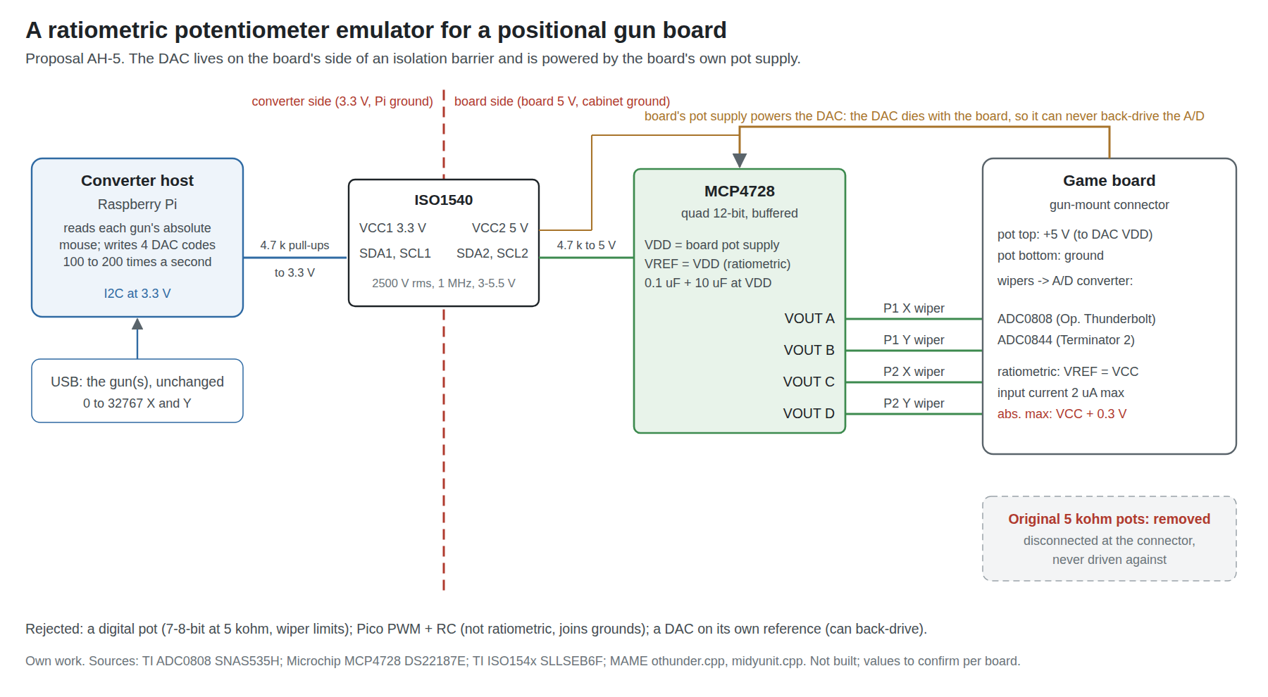
- Part: Microchip MCP4728. Four 12-bit buffered voltage outputs, one per channel needed for two guns; reference selectable between VDD and an internal 2.048 V; supply 2.7 to 5.5 V; settling about 6 µs; settings held in EEPROM and restored at power-up; I2C.4 Adafruit’s breakout (product 4470) was $7.50 and in stock on 2026-10-24.5
- Reference: VDD, from the board. The DAC is powered from the pot supply the board already provides (the line that fed the top of each pot) and set to use VDD as its reference. Its outputs are then fractions of the board’s own supply, so if the board’s 5 V sits at 4.9 V, the “wiper” moves with it, as a real pot’s would. Using the internal 2.048 V reference instead would break that and make the reading depend on the board’s supply voltage.
- No back-drive. Because the DAC takes its power from the board, it is unpowered whenever the board is, and its outputs cannot exceed the converter’s supply. This is the single most important property; the ADC0808’s absolute maximum makes it non-negotiable.3
- Resolution. Twelve bits into an eight-bit converter is sixteen DAC steps per converter step. The gun’s own 0–32767 report is far finer than either.
- Wiring. At the gun-mount connector, each pot’s wiper wire goes to a DAC output, the top-of-pot wire to the DAC’s VDD, and the bottom wire to its ground. The pots themselves are disconnected, not driven against.
The DAC is written by the converter’s host: on a Raspberry Pi, a small program reads each gun’s absolute mouse (as OpenJVS does) and writes the two channels per gun, perhaps 100 to 200 times a second, well above any game’s frame rate. No such program exists in OpenJVS or elsewhere that was found; it is a short piece of new code (proposal AH-5).
Why not a digital potentiometer? A digital pot (Microchip’s MCP41xx family, for example) is literally a resistor ladder and would be ratiometric by construction. It loses on two counts: the common 5 kΩ parts have 7- or 8-bit resolution, about the same as the board’s converter, so every quantisation step shows; and the wiper is a string of analogue switches with tens of ohms of wiper resistance and limits on wiper current that a buffered DAC output does not have. The DAC is simpler to reason about.
Why not PWM from the Pico and an RC filter? It would work for a DC level and costs nothing, but its ripple and settling trade against each other, its reference is the Pico’s 3.3 V (not ratiometric to the board), and it puts the gun’s microcontroller on the cabinet’s ground. The project’s gun is kept unchanged on purpose (Volume 1).
4.4 Isolation and the I2C level problem
The MCP4728’s I2C inputs are Schmitt triggers with a minimum high level of 0.7 × VDD,4 which at the board’s 5 V is 3.5 V. A Raspberry Pi drives 3.3 V. Some level translation is required regardless.
Choosing an isolator for that job solves a second problem at no extra cost. TI’s ISO1540 is a bidirectional I2C isolator: 3 to 5.5 V on each side, up to 1 MHz, 2500 V rms for one minute under UL 1577, with “isolate grounds, and prevent noise currents from entering the local ground” in its description.6 Side 1 runs from the Pi’s 3.3 V, side 2 from the board’s 5 V, and the pull-ups on each side go to that side’s supply. The converter’s ground and the cabinet’s ground are then never joined through the DAC wiring. TI now lists the ISO1640 as a drop-in successor.7
The ground matters because the converter is also connected to the gun, and the gun to a 24 V brick (Power Supplies), while the cabinet’s ground is tied to mains earth and to a CRT chassis. Volume 5 takes up grounding for the whole installation.
4.5 Calibration, mounting and the cabinets it fits
Positional cabinets calibrate in software, by shooting three targets with the gun’s own sights (Arcade Light Guns Vol 3). With a DAC in place of the pots, that calibration maps DAC codes to screen positions, so the converter should send codes that span a plausible pot swing and leave the rest to the game: the gun’s IR calibration makes it report true screen position, and the game’s three-point calibration absorbs any offset and scale. Terminator 2’s warning still applies, now for a different reason: “if you change boards or replace ROMs, RAMs, or the battery, you must recalibrate the guns. Guns do not operate unless they are calibrated.”8
The physical question is where the gun goes. These cabinets have mounted guns, and the original mount is the pot assembly. Two arrangements make sense:
- A handheld gun on a tether, with the IR emitters on the bezel and the mount left empty or removed. This loses the cabinet’s character but gives the game a better gun than it ever had.
- The project’s gun mechanism in the original mounted shell, the pots disconnected and the gun’s camera behind the muzzle, aiming from the mount’s pivot. The mount then only holds the gun; the camera does the measuring. That keeps the cabinet’s look, and it is how Blamcon’s Terminator 2 conversion re-houses the gun (its version is handheld and talks USB to a computer, not to the original board).9
Which cabinets this fits, from the manuals: Operation Thunderbolt and Space Gun (Taito), Beast Busters (SNK), Line of Fire, Laser Ghost and Alien3: The Gun (Sega), Terminator 2 and Revolution X (Midway), and the 2014 fixed-gun cabinets of Aliens Armageddon and Deadstorm Pirates SE, all listed in Arcade Light Guns Vol 3. Each needs its own check of the pot supply voltage and connector before anything is wired.
4.6 Optical boards: what the board times
An optical board does not want a position at all. It wants the gun’s sensor to report light at the instant its own picture is drawn at the aim point, and it converts that instant into a position with its own counters (CRT Timing explains the measurement in detail).
The manuals show the interfaces a converter would have to drive:
Table 1 — The manuals show the interfaces a converter would have to drive
| Board | What the gun supplies | Where the timing is done | Source |
|---|---|---|---|
| Operation Wolf (Taito, 1987) | A sensor board on ±12 V with one output, SENSOR OUT on a shielded lead | On the game board (“light gun position can be latched to inputs on v-blank”, MAME) | Arcade Light Guns Vol 1 |
| Point Blank (Namco, 1994) | A three-wire sensor PCB per gun | A separate position PCB fed with the game board’s C.SYNC | Arcade Light Guns Vol 2 |
| Virtua Cop (Sega Model 2, 1994) | A sensor unit, COP-2020 | A gun-sensor board on an RGB loom | same |
| Time Crisis 3 (Namco System 246) | A sensor in the gun | The TSS-I/O on JVS, from composite sync (Volume 2) | Miceli10 |
The last row is the reason Volume 3 matters: where the timing board is itself a JVS I/O, an emulated I/O removes the optical problem entirely. Only the boards that time the pulse themselves, the first three rows and their kind, are left for this section.
4.7 A pulse synthesiser, in principle
A converter for an optical board would replace the gun’s sensor output with a pulse it generates itself:
- Take the board’s sync. A JAMMA board puts negative composite sync on its edge connector with the video;11 a sync separator recovers horizontal and vertical timing from it. CRT Timing Vol 8 chooses the TI LMH1980 for the same job on the bench (decision CT-2).
- Know where the gun points, as a fraction of the visible picture, from the gun’s absolute report.
- Convert that to a line number and a delay. At the 15.7 kHz line rate of a standard-resolution arcade monitor, a line lasts about 63.5 µs (Miceli uses the same figure for the System 246’s timing10); the aim’s Y picks the line counted from vertical sync, and its X the delay from that line’s horizontal sync.
- Fire the pulse on the board’s sensor input at that line and delay, once per frame while the trigger is held (or as the game expects).
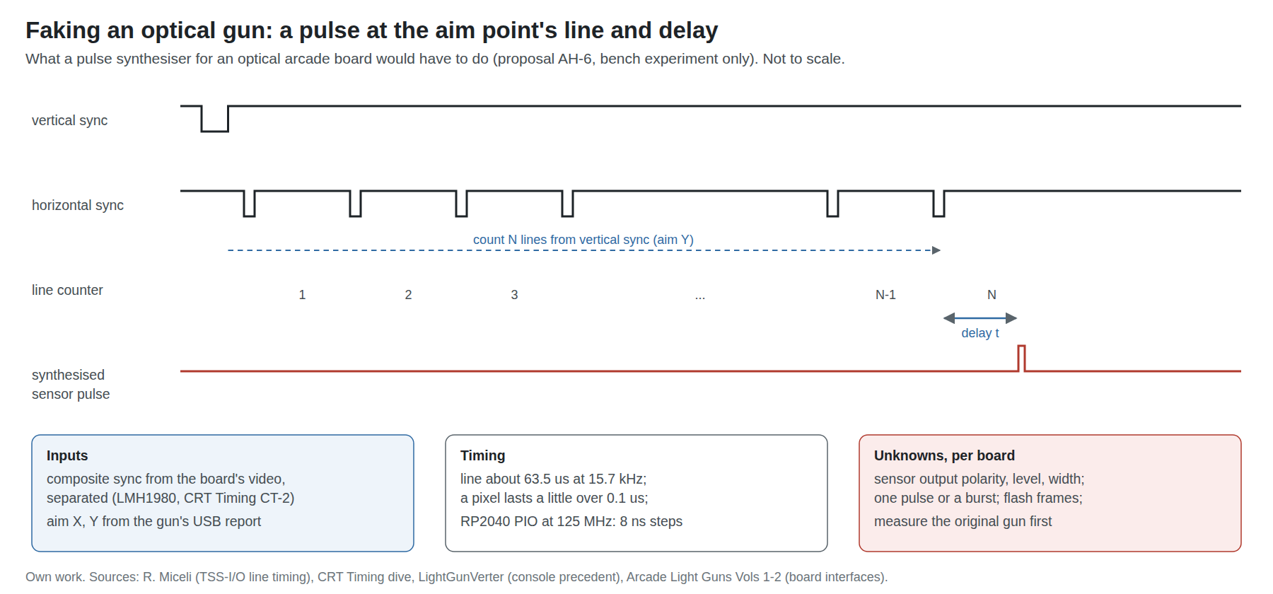
The timing resolution needed is a fraction of a pixel. With roughly 50 µs of visible line and a few hundred pixels across it, a pixel lasts a little over 0.1 µs, so the pulse must land within tens of nanoseconds of its target, every frame, without drift. The Pico’s PIO state machines, clocked from the system clock, resolve 8 ns at 125 MHz, which makes the RP2040 a credible core for the synthesiser; a Linux host cannot do this part at all and would only pass the aim to it.
The method has been shown to work, on consoles rather than arcade boards. The LightGunVerter, by the GitHub author charcole (“Charlie” in Hackaday’s write-up; open source under a non-commercial licence), takes a console’s composite video, aims with a Wii Remote, and flashes an LED pressed into the original gun’s barrel “at the moment that part of the CRT would have lit up”, for “almost all lightgun games/systems from the NES all the way up to the Dreamcast”.1213 It drives the gun’s own sensor optically rather than its output wire, which avoids having to match the sensor’s electrical behaviour at all. That arrangement belongs to Original Consoles; for an arcade cabinet it is the obvious first experiment.
4.8 Why this is a research project, not a build
Every arcade optical board found for this dive differs in exactly the places a synthesiser must match:
- The sensor’s electrical output is not documented. No manual read for Arcade Light Guns includes a sensor board’s circuit. Polarity, level (Operation Wolf’s board runs on ±12 V), pulse width and whether the board expects one pulse or a burst all have to be measured on the real thing.
- What the board does with the pulse differs. Some latch on the first pulse after the trigger, some on every frame, some flash the screen white first (Arcade Light Guns Vol 2 has CarnEvil’s flash-brightness setting) and expect the pulse only on the flashed frame.
- No arcade implementation was found. Searches on 2026-10-24 for a sync-timed converter for Namco, Konami, Taito or Sega optical arcade boards found forum ideas and an unfinished sketch, nothing published as working.
So the honest position is the one Arcade Light Guns Vol 6 takes for the CRT problem: keep the CRT, or replace the gun system. A pulse synthesiser is the third option in principle, to be attempted only with a specific board on the bench and the ADP3450 on its sensor input (proposal AH-6).
4.9 The other answer: replace the board
For a JAMMA cabinet whose gun board is dead or optical, the common answer is not to keep the board at all but to put a computer in its place and run the game in emulation, with a modern gun on USB. Ultimarc’s J-PAC is the standard bridge: it connects “a JAMMA arcade cabinet to a VGA card and keyboard port or USB port on a PC”, passes the PC’s video through (“does not convert or process the video signal in any way except amplify it”; “is not a scan converter”), and turns the cabinet’s controls into key presses; $59.00 on Ultimarc’s page, 2026-10-24.14 It has no gun features: the gun connects to the PC directly.
Recalbox’s JVS board (a Raspberry Pi 5 HAT, crowdfunded in May and June 2026) does the same for JVS cabinets, “in place of your cabinet’s original system”, keeping the cabinet’s I/O board and offering 15, 24 and 31 kHz video; its gun support was not described in the announcement read.15
That route is emulation and is covered by PC (Windows), Linux and Retro Distros and MiSTer FPGA. What it needs from the cabinet (power, coin and start wiring, the solenoid supply) is in Volume 5.
4.10 Why this, and why not the others
Table 2 — 4.10 Why this, and why not the others
| Choice | Pick | Rejected, and why |
|---|---|---|
| Pot replacement | MCP4728 quad 12-bit DAC, VDD reference from the board’s pot supply | Digital pot: 7–8-bit at 5 kΩ, wiper resistance and current limits. PWM + RC from the Pico: not ratiometric, ripple against settling, puts the gun on the cabinet ground. A DAC with its own reference: not ratiometric, and can back-drive an unpowered board |
| I2C translation | ISO1540 isolator (or its successor ISO1640) | A plain level shifter: translates but leaves the grounds joined. An optocoupler pair: slow and awkward for bidirectional I2C |
| Optical boards | Keep the CRT, or replace the board; synthesiser only as a bench experiment on a specific board | Building a general synthesiser now: the sensor interfaces are undocumented and differ per board |
| Dead JAMMA gun board | Emulation via J-PAC and a PC (other dives) | Re-creating the board: out of scope |
4.11 What could not be verified
- The ADC0844’s datasheet was not read; its behaviour is assumed similar to the ADC0808’s (both are ratiometric 8-bit converters of the same family) and should be checked before wiring a Terminator 2.
- Each positional cabinet’s pot supply voltage and connector pinout; the manuals give the pots, not always the voltages.
- That any game accepts a DAC in place of its pots without complaint (a game that checks for a noisy or moving value at rest, for example).
- Any arcade optical board’s sensor electrical interface.
- Price of the ISO1540 at a distributor (not read on 2026-10-24).
Sources
Footnotes
-
MAME,
src/mame/taito/othunder.cpp(Operation Thunderbolt driver: board notes, ADC0808 mapping), master branch, https://github.com/mamedev/mame — read 2026-10-24. ↩ -
MAME,
src/mame/williams/midyunit.cpp(Y-unit driver: “ADC0844 … U2 on Coil Lamp Driver Board (A-14915)”), master branch — read 2026-10-24. ↩ -
Texas Instruments, ADC0808-N/ADC0809-N 8-Bit µP Compatible A/D Converters with 8-Channel Multiplexer, SNAS535H, October 1999, revised March 2013: absolute maximum ratings, converter specifications, “Ratiometric conversion” — read 2026-10-24. ↩ ↩2 ↩3
-
Microchip Technology, MCP4728 12-Bit, Quad Digital-to-Analog Converter with EEPROM Memory, DS22187E (2010): features, electrical characteristics (VIH 0.7 VDD on SDA, SCL, LDAC; settling 6 µs; INL) — read 2026-10-24. ↩ ↩2
-
Adafruit, “Adafruit MCP4728 Quad DAC with EEPROM - STEMMA QT / Qwiic”, product 4470, https://www.adafruit.com/product/4470 — $7.50, in stock, read 2026-10-24. ↩
-
Texas Instruments, ISO154x Low-Power Bidirectional I2C Isolators, SLLSEB6F, July 2012, revised December 2022 — read 2026-10-24. ↩
-
Texas Instruments, ISO1540 product page (status Active; ISO1640 listed as drop-in replacement), https://www.ti.com/product/ISO1540 — read 2026-10-24. ↩
-
Midway, Terminator 2: Judgment Day operations manual 16-40009-101, December 1991, as quoted in Arcade Light Guns Vol 3. ↩
-
Blamcon / Props 3D Pro, “Conversion: Terminator 2 Arcade”, https://blamcon.com/light-gun-conversions/conversion-terminator-2-arcade/ (images dated August–September 2025) — read 2026-10-24. ↩
-
Ryan Miceli, “Light Gun Hacking Part 1: Using Namco light guns in Unity”, icode4.coffee, 27 October 2022, https://icode4.coffee/?p=655 — read 2026-10-24. ↩ ↩2
-
Wikipedia, “Japan Amusement Machine and Marketing Association” (JAMMA connector), https://en.wikipedia.org/wiki/Japan_Amusement_Machine_and_Marketing_Association — read 2026-10-24. ↩
-
charcole, LCDZapper / LightGunVerter,
READMEand LightGunVerter Instructions (PDF), https://github.com/charcole/LCDZapper (last pushed 12 August 2020; non-commercial licence) — read 2026-10-24. ↩ -
Jenny List, “Tricking Duck Hunt To See A Modern LCD TV As CRT”, Hackaday, 30 August 2016, https://hackaday.com/2016/08/30/tricking-duck-hunt-to-see-a-modern-lcd-tv-as-crt/ — read 2026-10-24. ↩
-
Ultimarc, “J-PAC JAMMA interface”, https://www.ultimarc.com/control-interfaces/j-pac-en/j-pac-jamma-interface/ — $59.00, read 2026-10-24. ↩
-
Recalbox, “Official! Recalbox JVS: plug it in, power it on, play — the Kickstarter is live”, 29 May 2026, https://www.recalbox.com/blog/2026-05-29-recalbox-jvs-kickstarter-borne-arcade-retrogaming/ — read 2026-10-24. ↩
Comments (0)