Chauchat · Volume 5
How It Works: Long Recoil From an Open Bolt
The parts and their three sets of names, the three phases of the cycle as the French Army taught them, the rotating bolt head and its stop, the barrel latch, the recoil intensifier at the muzzle, a trigger that the barrel itself trips, and why the gun fires only about 240 rounds a minute
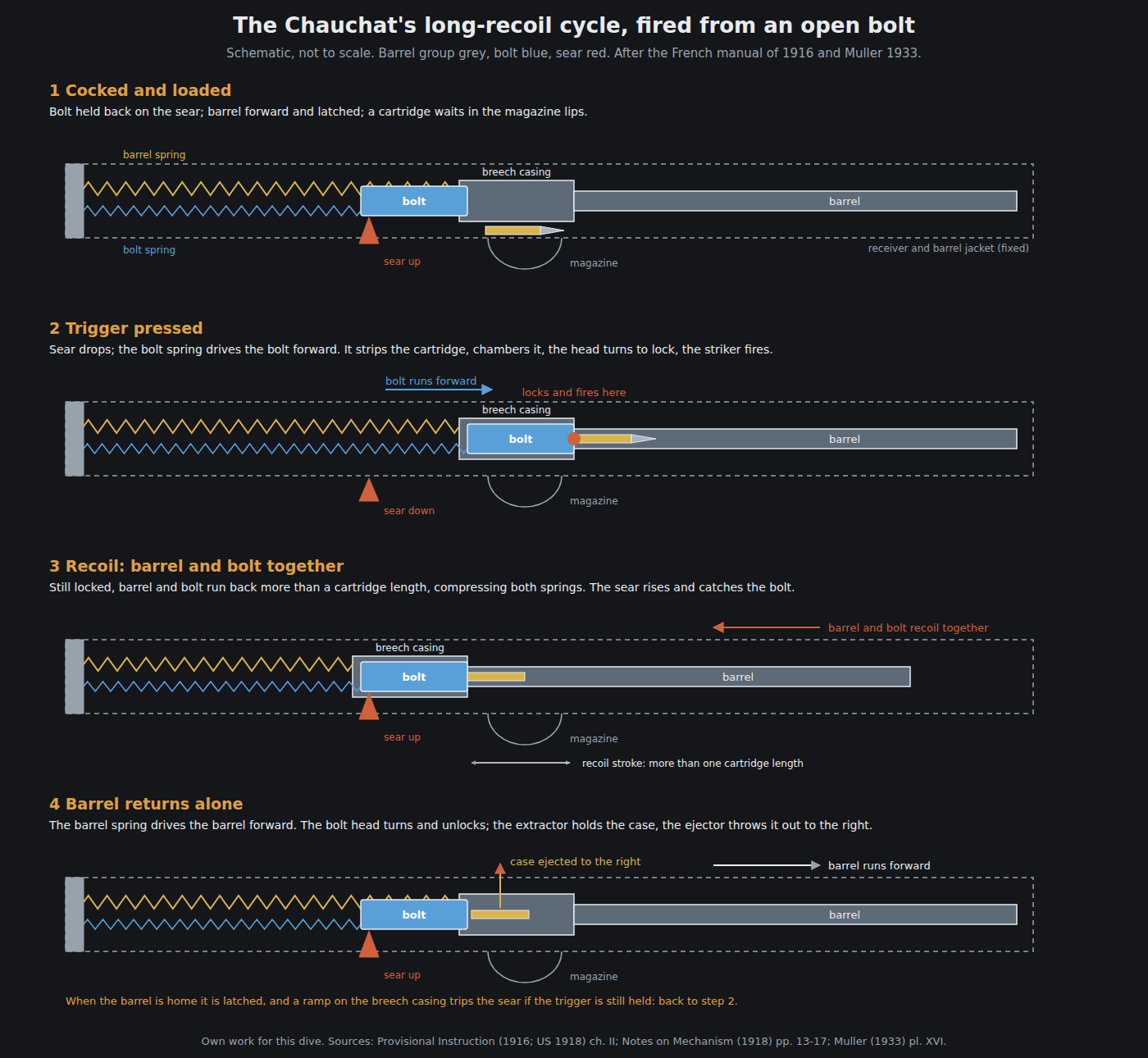
5.1 The principle
The French Army’s manual begins with the classification: the Fusil-mitrailleur modèle 1915 is “an automatic rifle utilizing the recoil strength. It is classed among the guns of this category acting by long recoil of the barrel.”1 Muller’s 1933 teaching text is shorter: “Fonctionne par emploi du recul avec long recul du canon.”2
In a long-recoil gun the barrel and the bolt stay locked together for the whole of the rearward stroke, which is longer than a cartridge. Only then are they separated: the bolt is held, and the barrel goes forward alone. Everything that a short-recoil or gas gun does in a few millimetres of travel (unlocking, extraction, making room for a new round) the Chauchat does by moving the entire barrel back and forth inside its jacket. Chinn puts the stroke as “a distance greater than the combined overall length of the cartridge case and bullet”.3 Volume 1 traces the principle to Browning’s patent of 1900.
The Chauchat also fires from an open bolt: at rest, between bursts, the bolt is held back and the chamber is empty. Pressing the trigger releases the bolt, which chambers a round and fires it in one forward stroke. Armes Françaises lists “tir culasse ouverte” among the gun’s characteristics, and the 1916 manual says that when the trigger is released “the firing stops, barrel forward, breech open”.41
5.2 Three sets of names
The French manual, the American translation of it, and the American armourers’ notes of 1918 each name the parts differently. The table below gives all three, so that the sources can be read side by side.
Table 1 — Three sets of names
| French (Muller 1933) | US translation of the 1916 manual (1918) | US Notes on Mechanism (1918) | What it is |
|---|---|---|---|
| Manchon-guide (tube-enveloppe) | Barrel cover guide | Housing (radiator casing and breech housing) | The fixed tube that encloses the moving barrel |
| Carcasse | Receiver (side plates, transoms) | Rifle carriage | The stamped frame under the tube, with grip, magazine catch and bipod |
| Boîte de culasse | Breech casing | Breech casing | Barrel extension that houses the bolt |
| Fourrure | Barrel sleeve | Barrel sleeve | Collar on the barrel, with the groove for the latch |
| Culasse mobile = tête mobile + chien | Movable breech = movable bolt head + cocking bolt | Bolt mechanism = bolt head + bolt body | The two-piece bolt |
| Bonhomme-arrêtoir de tête mobile | Movable bolt head stop | Bolt head stop | Keeps the head from turning until the round is chambered |
| Ressort récupérateur de canon | Barrel recoil spring | Recoil spring | Returns the barrel |
| Ressort récupérateur de culasse | Breech recoil spring (“also the part of main spring”) | Mainspring | Drives the bolt forward and fires |
| Bouchon d’appui | Plug | Spring guide cap | Screwed rear cap that holds both springs |
| Alimentateur, crochet de culasse | Carrier, breech hook | Feed piece, sear notch | Arm under the bolt that pushes the cartridge; its hook engages the sear |
| Volet-guide de cartouches, bielle | Cartridge guiding shuttle, connecting rod | Cartridge guide, cartridge guide cam | Flap that lifts the bullet’s nose to the chamber |
| Levier-arrêtoir de canon | Barrel lever stop | Barrel catch | Latches the returned barrel |
| Renforceur de recul | Recoil intensifier (front sight carrier) | Flash screen coupling | Muzzle cup that adds rearward thrust |
| Détente, barrette, mentonnet, levier de gâchette, gâchette | Trigger, bar, strut, sear lever, sear | Trigger, trigger bar, hand sear, sear lever, sear | The trigger train |
| Came (sûreté) | Safety lock and lifter | Regulator cam | The S, M, C selector |
Sources: Muller 1933 pp. 47–55; Provisional Instruction ch. I; Notes on Mechanism pp. 3–6.215
5.3 The parts
The American translation divides the gun into a non-recoiling part and a movable part.1
Fixed. The barrel cover guide is two sheet-steel tubes joined by a front screw collar, with the flash cover and front-sight carrier at the muzzle, eighteen air holes at the front, the ejection opening on the right, and an opening underneath “in which slides the carrier fixed to the movable breech”. At the rear it ends in a collar into which is screwed “the plug sustaining the recoil springs”. Under it, the receiver is two side plates joined by three transoms (one carrying the bipod, one carrying the barrel latch and the cartridge guide, one carrying the carrying handle and the magazine catch) and fixed at the back to the butt. The firing mechanism sits in its own pressed housing with the pistol grip.1
Moving. The barrel, with an aluminium radiator over three-quarters of its length, is screwed into the breech casing at the rear. Two springs live in the plug at the back: the barrel recoil spring, which the translation rates at a “relaxing strength, 26 to 20 pounds”, and inside it the breech recoil spring, which also serves as the mainspring.1 The bolt is in two pieces: the bolt head, carrying the locking lugs, extractor and ejector, and the bolt body (the “cocking bolt”), which carries the firing pin and has helical cam grooves in which two working lugs at the back of the head run. Under the bolt body is the carrier, with the hook that the sear engages and the operating handle on the right; a connecting rod running from it works the cartridge guide.1
5.4 Phase one: barrel and bolt recoil together
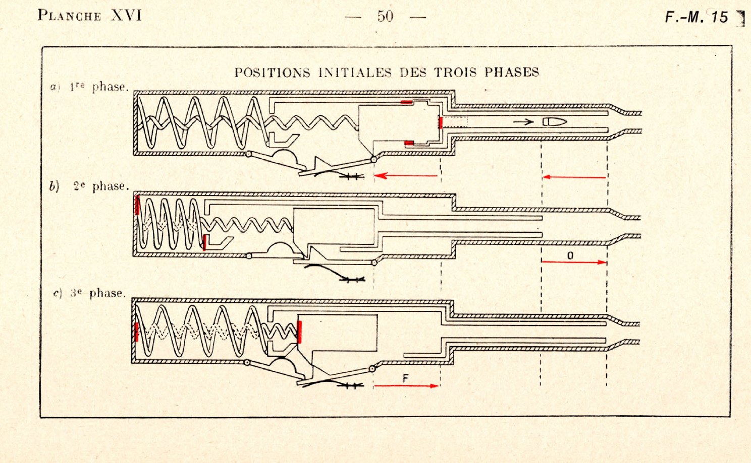
The French manual divides the cycle into three phases, each with its “motive power”.12 The first:
“Recoil of the barrel and breech. (The two pieces joined.) Motive power. The gas. One operation. Cocking. The first shot occurs, the gas acting on the movable breech sends it backwards. As the breech is bolted to the barrel, this is sent backward, too. The recoil springs are compressed. … the cocking is effected. Maintenance of the cocking.—The maintenance of the cocking is secured by the hooking of the breech hook on the sear head.”1
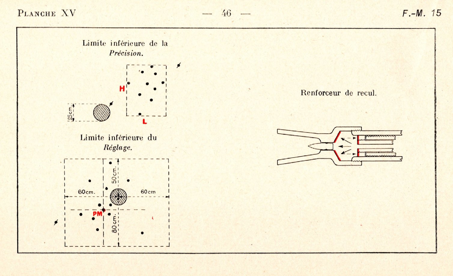
The Camp Kearny notes add that at the end of this phase “The cartridge guide cam raises the cartridge guide up in front of the chamber to direct the feeding of the cartridge.”5 Muller adds the appoint, the extra push, from the muzzle: “Renforceur de recul utilisant la détente des gaz à la bouche” (below).2
5.5 Phase two: the barrel returns alone
The motive power is the barrel recoil spring, and there are four operations: withdrawal of the firing pin, unlocking, extraction and ejection.1
- Firing pin withdrawn. The bolt body is held by the sear, so only the head can follow the barrel. The head first moves “8 millim.” along the straight part of the helical grooves, which draws the firing pin back from the face.1
- Unlocking. The head’s working lugs then reach the helical part of the grooves and the head turns, freeing its locking lugs from their shoulders in the breech casing. The 1918 notes describe the rotation as clockwise; Muller, as “de gauche à droite”.52
- Extraction. “The barrel going on with its run, quits the movable breech. The cartridge case … being, on the other hand, detained by the extractor claw, finds itself pulled out of the chamber.”1 The case is pulled off the barrel, not drawn back by the bolt.
- Ejection. When there is enough room, “the cartridge case pushed by the ejector pivots around the extractor and is projected to the right passing through the ejection opening”.1
The barrel finishes its run and is latched forward.
5.6 Phase three: the bolt goes forward
The motive power is the breech recoil spring, and there are three operations: feeding and closing, locking, and firing.1
“The barrel being brought back to its firing position the breech casing acting on the firing mechanism sets free the breech. Through the action of the breech recoil spring … the latter is sent forward. In this motion the anterior part of the carrier’s arm, meeting a cartridge raised up by the clip, pushes it forward and upward in the direction of the chamber. The movable head lower locking lug acting then on the cartridge, introduces it into the chamber”.1
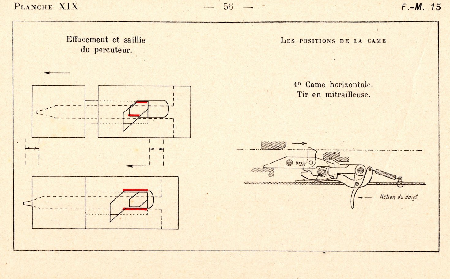
When the head meets the barrel it stops, and the bolt body, still driven by the spring, turns it by the helical grooves into its locked position. The body then runs on along the straight part of the grooves, “and the firing pin protrudes in the hollow face, hence striking.”1 There is no separate hammer or striker spring: the bolt spring fires the cartridge, and the firing pin cannot reach the primer until the head has turned and locked.
5.7 Locking: the bolt head and its stop
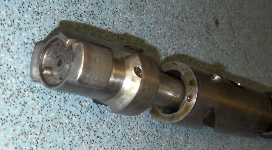
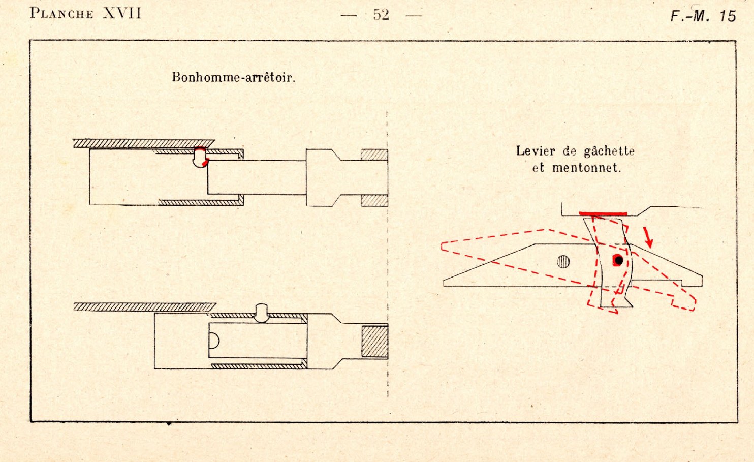
The head must not turn while it is travelling forward with a cartridge in front of it, or its lugs would not enter their recesses. A spring-loaded bolt head stop in the bolt body drops a pointed stud into a notch in the head and holds it “in the position ‘lugs vertical’”. It can rise out of the notch only when it reaches the ejection opening, which happens as the round is seated; then “the action of the notch’s inclined edges on the stop center punch” lifts it and lets the head turn.1 The Camp Kearny notes put the purpose in a sentence: “The bolt head stop prevents the closing of the bolt head on the bolt body until the cartridge is seated in the chamber.”5
How many locking lugs? The 1918 American notes say “two locking lugs on the bolt head rotating into the locking recesses of the breech casing”, turned by “the guide lugs on the bolt head” in the cam cuts.5 Chinn’s 1951 account says “This rotary bolt has four locking lugs”.3 The bolt head has two locking lugs at the front and two working (guide) lugs at the back, which would make four lugs in all; Chinn may have counted both pairs. That reconciliation is this dive’s reading and is not stated in any source.
Chinn also describes “a spring-loaded plunger projecting from the face of the bolt” that the rim of a seated cartridge must push back before the striker can reach the primer.3 Neither period manual describes such a safety. The spring-loaded part projecting from the bolt face that both manuals do describe is the ejector, visible in the photograph above. Chinn’s plunger is probably the ejector, but that could not be confirmed.
5.8 The barrel latch
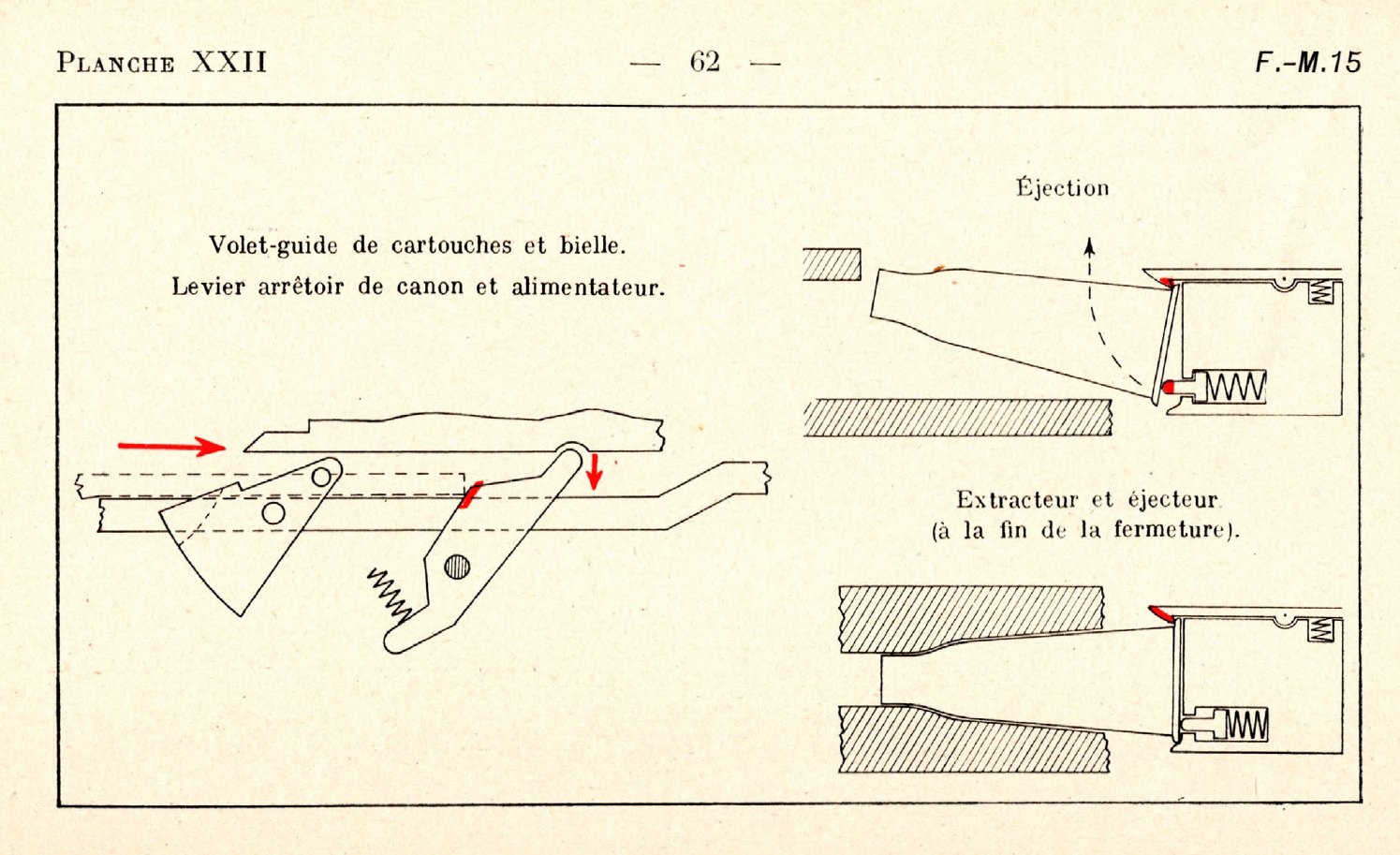
When the barrel slams home there is a risk it rebounds. The barrel lever stop, on the transom under the barrel, pops up into a circular notch in the barrel sleeve to hold it.1 Because the barrel must be free to recoil when the next shot fires, the latch has to be released first, and the bolt does it: “when going forward, the carrier arm taking support on the body of the lever stop, forces the nose to lower. The barrel is then freed.”1 The notes of 1918 say the same: “As the bolt mechanism moves forward to fire the cartridge the end of the feed piece strikes the barrel catch, disengaging it from the groove in the barrel”.5
5.9 The recoil intensifier
A recoil-operated gun with a heavy moving barrel needs all the rearward push it can get. The Chauchat takes extra from the muzzle blast. In the French description, the front-sight carrier “presents internally a truncated chamber in which the gas expands, when the bullet is shot out of the barrel … The gas acting backward on the fore part of the barrel nut, increases the recoil action”.1 The 1918 notes call the part a “flash screen coupling … cap-shaped, and … designed to trap a portion of powder gas and direct it against the muzzle end of the barrel, thereby aiding the recoil of the barrel group”.5
The barrel nut takes the gas and gets dirty. The French manual singles it out: “the part that gets dirty, generally, is the barrel nut”, and supplies a special scraper for it (Volume 8).1
5.10 Feeding: the carrier and the cartridge guide
The magazine hooks under the receiver with its open end at the rear, between the bipod transom and the shuttle transom (Volume 6). Its lips hold the top cartridge in the path of the carrier, the arm that runs under the bolt.1
When the bolt goes forward, the carrier arm takes the top cartridge by its base and drives it forward; “the point of the bullet, meeting the ramp of the cartridge guiding shuttle, is lifted and the cartridge is directed toward the chamber in which it is fully introduced by the movable head”. The next round, pushed up by the magazine spring, presses against the underside of the carrier, which stops it rising until the bolt has gone back over it.1 The shuttle has to move out of the carrier’s way once the round is started, so it is pivoted and worked up and down by a roller running in an S-shaped groove in the connecting rod attached to the bolt.1
Two consequences follow. Feeding is a forward shove from below, and if the round is presented too high, too low or tilted, the bullet’s point strikes the top of the breech casing or the shuttle transom and the bolt stops short. Both manuals list that as the commonest feed stoppage, and both blame the magazine.15 And the gun cannot be fed except from a magazine; for single loading the French issued an auget, a feed trough fitted in the magazine’s place. The 1918 notes say it “enables cartridges to be fed by hand at the rate of forty per minute”.52
5.11 The trigger mechanism and the three settings
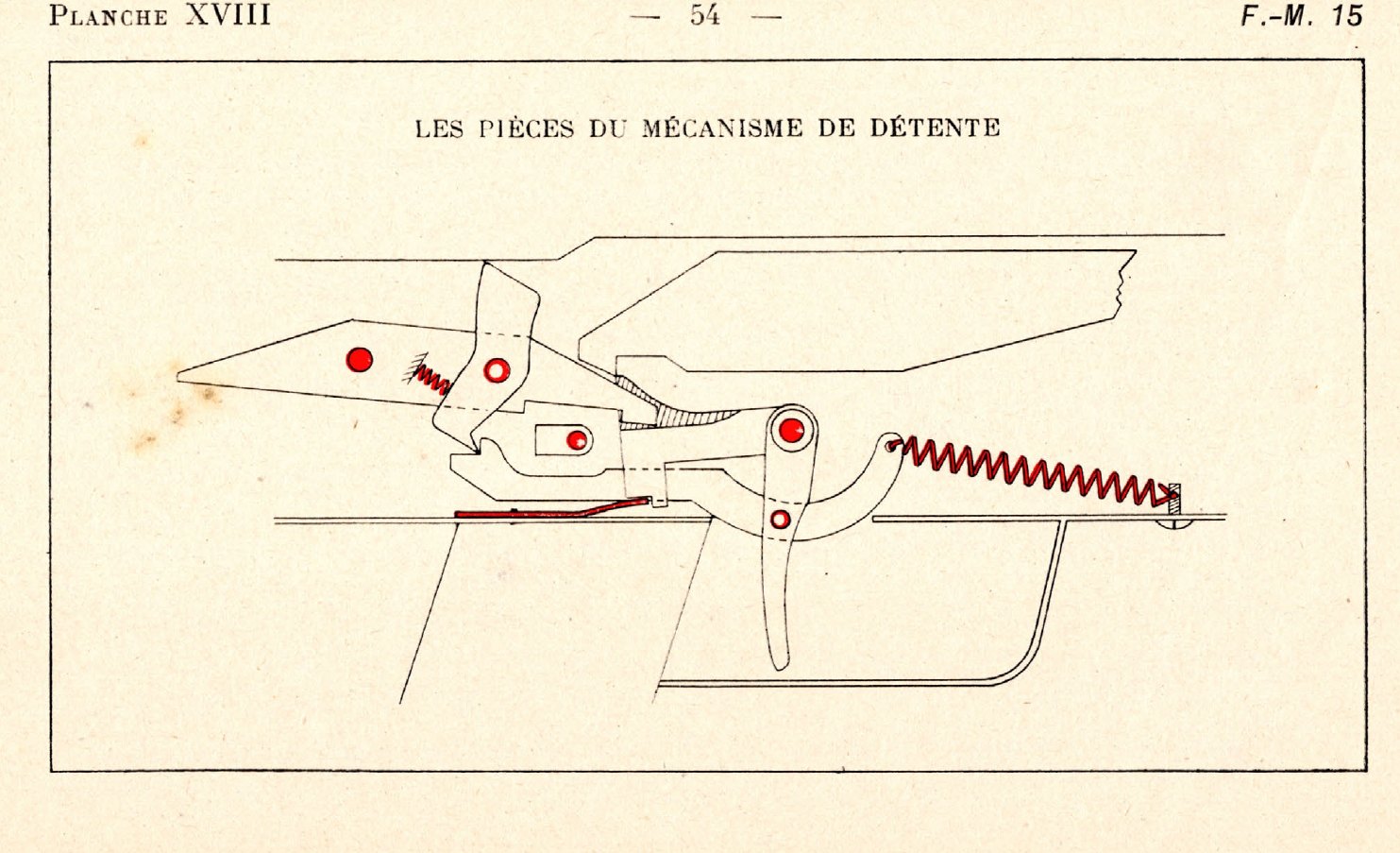
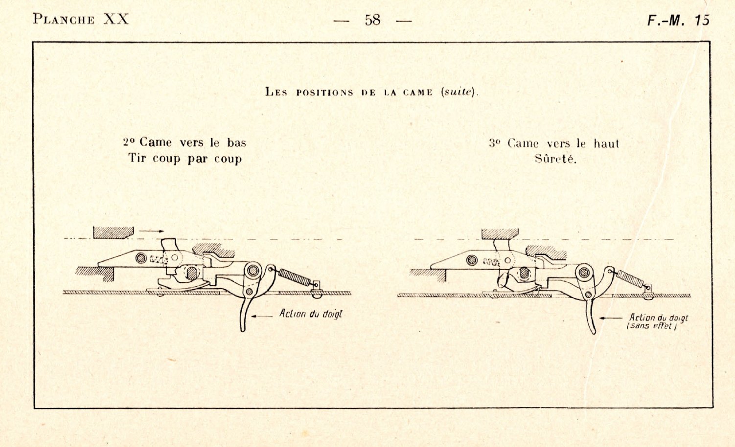
The trigger mechanism is the most unusual part of the gun, because in automatic fire it is the barrel, not the trigger, that releases each shot.
The selector is a lever on the left of the trigger housing with three marks: S (sûreté, safe), M (mitrailleuse, automatic) and C (coup par coup, single shots).26 (Chinn’s “C … control” is an error; Volume 1.) Inside, it is a cam, the “lifter” of the American translation, that bears on different parts of the trigger train in each position.
Automatic (M). The cam is horizontal and inactive. Pulling the trigger draws the bar back; the bar tips a small pivoted strut (the mentonnet) so that its rounded head stands up in the path of the breech casing. When the barrel returns to battery, a slope on the underside of the breech casing presses down on the strut; the strut presses down the sear lever, which pulls the sear out of the carrier’s hook, and the bolt flies forward. On the next recoil the casing slides off the strut, the sear spring lifts the sear to catch the bolt again, and the cycle repeats as long as the trigger is held. The French manual’s summary: “it is the barrel which by its breech casing regulates in the automatic firing the discharge, the gunner’s only task being to keep his finger on the trigger.”1
Single shots (C). The cam is turned down onto the trigger bar. When the trigger is pressed the bar tips the strut and the bolt is released as before, but the bar also slides down the cam’s inclined face, which pulls it clear of the strut. The strut, sprung back, drops below the path of the breech casing, so the returning barrel rides over it without releasing the bolt. “If you want to free the breech and at the same time fire the following shot, you must release the trigger”.1
Safe (S). The cam is turned up under the sear lever, so “any lowering of this lever is impossible; accordingly it is the same thing for the sear. In consequence, the action of the trigger cannot produce the freeing of the breech”.1 The bolt stays back. Safe holds an open bolt; it does not lock a closed one.
5.12 Cooling
The barrel has a ribbed aluminium radiator over three-quarters of its length, and the jacket has air holes at the front.1 The Camp Kearny notes add that “The rapid backward and forward motion of the barrel causes cool air to be drawn in through holes in the radiator casing, thereby aiding the cooling of the barrel”.5 The weak point is not the barrel but the sleeve that slides in the jacket: when it is hot it expands and sticks, and the barrel fails to return. Volume 8 gives the manual’s figures.
5.13 What the design means for the shooter
- A slow rate of fire. Muller gives a cyclic rate of 240 rounds a minute.2 Every shot requires the whole barrel and bolt to go back, the barrel to come forward, and only then the bolt. In automatic fire the next shot is not released until the barrel is fully home.
- A long, shoving recoil. Muller’s plates show the mass of the barrel, bolt and springs travelling back into the butt. The 1918 notes warn: “rest the cheek well upon the breech housing so the spring guide cap will not injure the gunners face.”5 The French training centre at Châlons photographed what happens otherwise (Volume 8).
- It must be held hard. A gun held loosely moves back as a whole, the barrel does not recoil far enough, and the bolt is not caught: “the barrel will not recoil far enough to engage the feed piece in the sear”.5
- Open bolt. The chamber stays empty between bursts, which helps a hot barrel, and the bolt’s forward run before each shot moves the point of aim.
- The barrel moves inside a tube. Dirt between the radiator and the jacket stops the gun. The French instruction warns the gunner to avoid “the touching of the barrel cover guide to the ground as anything getting between the barrel cover and the radiator interferes with the firing.”1
5.14 Conflicts and what could not be established
- Locking lugs: two (US notes, 1918) against four (Chinn, 1951); reconciled above as two locking plus two working lugs, which is this dive’s reading.
- Striker travel after locking: the 1916 manual gives 8 mm of straight groove for withdrawal; Chinn says the striker “must advance one full half inch after the bolt is closed and locked”. Not reconciled.
- Chinn’s firing-pin plunger: not in either manual; probably the ejector.
- Recoil stroke: no source gives the barrel’s travel in millimetres. Chinn says “greater than” the cartridge’s overall length.
- Spring rating: “26 to 20 pounds” for the barrel spring is as printed in the US translation and is not explained.
References
Footnotes
-
Provisional Instruction on the Automatic Rifle, Model 1915 (Chauchat), translated from the French edition of February 1916, revised to 9 June 1917 at HQ AEF; reprinted by the Army War College, January 1918 (War Department Document No. 732), ch. I and ch. II §§ I–III, Part V. https://archive.org/details/provisionalinst00deptgoog, accessed 2026-10-19. ↩ ↩2 ↩3 ↩4 ↩5 ↩6 ↩7 ↩8 ↩9 ↩10 ↩11 ↩12 ↩13 ↩14 ↩15 ↩16 ↩17 ↩18 ↩19 ↩20 ↩21 ↩22 ↩23 ↩24 ↩25 ↩26 ↩27 ↩28 ↩29 ↩30
-
Cdt G.-H. Muller, preface by Gén. Tanant, Exposé schématique du fonctionnement des armes de petit calibre (Berger-Levrault, 1933), ch. II, pp. 46–62, planches XV–XXII. https://archive.org/details/expose-schematique-du-fonctionnment-des-armes-de-petit-calibre-by-tanant-1933, accessed 2026-10-19. ↩ ↩2 ↩3 ↩4 ↩5 ↩6 ↩7 ↩8
-
George M. Chinn, The Machine Gun, Vol. I (Bureau of Ordnance, 1951), pp. 238–240. https://archive.org/details/TheMachineGunVolume1ByGeorgeMChinn, accessed 2026-10-19. ↩ ↩2 ↩3
-
“Le fusil-mitrailleur de 8 mm CSRG modèle 1915”, Armes Françaises, http://armesfrancaises.free.fr/FM%20Chauchat.html, accessed 2026-10-19. ↩
-
School of Automatic Arms, 40th Division, Camp Kearny, Notes on Mechanism of the Chauchat Machine Rifle, Model 1915, February 1918, pp. 3–18. https://archive.org/details/chauchatautomaticriflemodel1915notesonmechanism, accessed 2026-10-19. ↩ ↩2 ↩3 ↩4 ↩5 ↩6 ↩7 ↩8 ↩9 ↩10 ↩11 ↩12
-
Henri Vuillemin, “Centenaire du Chauchat”, La Gazette des Armes no. 475, May 2015, p. 17, via Wayback copy of https://web.archive.org/web/20221118053755/http://fr.1001mags.com/parution/gazette-des-armes/numero-475-mai-2015/page-16-17-texte-integral, accessed 2026-10-19. ↩
Comments (0)