The History of Light Guns · Volume 2
Shooting the Television — Ralph Baer's Light Guns, the Odyssey Rifle and the First Arcade Duck, 1967 to 1979
The moment the target stopped carrying the sensor: a photoresistor in a Sears toy rifle, the 1968 patents, Magnavox's $25 Shooting Gallery that a desk lamp could beat, Atari's Qwak!, and the pong chips that put a rifle input on a single IC
2.1 Turning the arrangement round
Volume 1 ended with the problem a television posed. The 1930s rifle ranges put a photocell on every duck and a lamp in the gun. A television cannot carry a photocell per duck: the “duck” is a patch of phosphor that moves wherever the electronics put it. So the arrangement has to be reversed. The screen becomes the light source, and the gun becomes the detector. A photocell at the bottom of the barrel, behind a lens or simply behind a long tube, looks at a small patch of the screen; the console decides from what the gun reports whether that patch was the target.
That reversal creates a new problem the coin-machine men never had. A photocell on a duck in a dark cabinet only ever sees the gun’s flash. A photocell in a gun pointed at a living-room television sees the screen, the room lamps, the window and anything else bright in its field of view. Every television light gun since 1967 has been, at heart, an answer to the question “how does the gun know the light it sees is the target?” This volume follows the first three answers.
2.2 Sanders Associates, 1967: a photoresistor in a toy rifle
The first television light gun was built at Sanders Associates in Nashua, New Hampshire, in the skunk-works project Ralph Baer ran to put games on ordinary television sets. Baer’s own account, written from his lab notebooks, records that on 12 February 1967 his technician Bill Harrison “works on light gun (in radio case) … Device is a code detector”, and in September 1967 “‘Rifle II’ / light gun design by WLH”.1
The early guns used the long barrel itself as the optics. “Using their long barrel again as our ‘optics’ we positioned the photo sensor near the breech. That sensor was still a photo resistor. Now we could stand back five or six feet from the TV set and ‘shoot down’ target spots that the other player moved manually, or that were moved helter-skelter by Mason’s random-noise generator circuit”.1 For the sixth test unit Harrison bought a plastic rifle at a Sears store on Main Street in Nashua and rebuilt it:
“His new design used a transistor amplifier and a small light bulb to bias the photo resistor optically into a more sensitive region. This increased the sensitivity of the ‘gun’ and it worked like a charm even at considerable distances from the TV screen. The same ‘rifle’ was used again with what became TV Game #7, our Brown Box. Our assorted kids, the boys of course, really like shooting at the screen. They also figured out quickly that they could cheat by pointing the gun at some nearby fluorescent lamp and get a ‘hit’.”1
Two details are worth an engineer’s attention. The optical bias — a small lamp inside the gun shining on the photoresistor — moves a cadmium-sulphide cell off the steep, slow, high-resistance end of its curve, where a faint spot on a 1960s screen would barely register, into a region where a small change in light gives a usable change in resistance. And the cheating children found the failure mode that defines this whole volume on the first day.
Baer also built the first coded light gun. For a quiz game played over cable television, four white answer spots blinked during the answer time: the wrong answers “would rapidly blink an even number of times”, the correct one “an odd number of times, our ODD/EVEN code scheme”, and the gun carried “a simple circuit that allowed our light gun to recognize the difference between those odd and even counts … a crude digital code”.1 A gun that counts flashes cannot be fooled by a steady lamp. The idea did not reach a product for sixteen years, and when it did (Volume 3) it was Nintendo’s, not Sanders’.
2.3 The 1968 patents
Sanders filed on the light gun twice in the first months of 1968.
US 3,599,221, “Recording CRT Light Gun and Method” (Baer; filed 18 March 1968, granted 10 August 1971) grew out of Harrison’s 1967 code-detecting gun.2
US 3,728,480, “Television Gaming and Training Apparatus” (Baer; filed 22 March 1971 as a continuation of an application of 15 January 1968; granted 17 April 1973) is the broad Odyssey-era patent, and it describes the game gun plainly:3
“apparatus can be used for electronic target shooting by providing a gun having a photo-electric cell which is activated when a trigger is depressed. Thus, when the gun is aimed at a ‘dot’ displayed on the television screen, which ‘dot’ serves as the target … When a game is played using the target gun, also called a ‘light-gun,’ hits are shown on the screen by having one of the ‘dots’ disappear.”
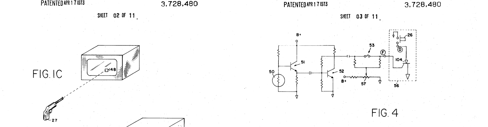
The circuit in Fig. 4 is the whole of the first commercial generation. “When the target gun is pointed at the target ‘dot’ on the television screen, a photocell 50 mounted at the end of the target gun barrel will detect the intensity modulated ‘dot.’ The detected signal is amplified by transistors 51 and 52. When the gun trigger switch 53 is closed, the amplified detected signal is applied to the gate electrode of a silicon controlled rectifier” which fires the crowbar that turns the dot generator off. The only defence against the room is a knob: “potentiometer 57 whereby the threshold level of photo cell 50 may be adjusted such that only when the gun is properly aligned with the target will the ‘dot’ disappear. This procedure assures that false hits due to stray or scattered light from the room will not be scored.”3
That is a level detector. It answers “is there more light in front of the barrel than the threshold?”, and nothing else. The SCR is a nice touch — it latches, so the dot stays off once hit until the game resets it — but the sensor cannot tell a phosphor dot from a lamp.
2.4 The Odyssey Shooting Gallery, 1972
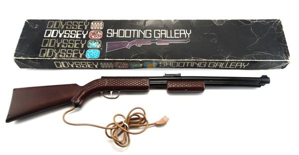
Magnavox licensed the Sanders work and released the Odyssey in 1972. The rifle was an accessory, the Shooting Gallery, model 1TL950, which “includes an ELECTRONIC RIFLE, two Printed Circuit Game Cards and 4 different Target Overlays in two sizes”, offering “6 variations”.14 Baer’s verdict on the business was blunt: Magnavox shipped “a very nice-looking, pump-action plastic ‘rifle,’ for which they provided a separate, large, in-store easel display”, but set “a steep $100 for the game unit plus six program cards”, “decided to charge another whopping $25 for the rifle”, sold mainly through its own franchised dealers, and ran television advertising that left “everyone … the impression that the game would only work with Magnavox TV sets”.1
The manual explains the gun’s operation in four sentences:
“It is designed to extinguish a light (or target) that appears on the television screen when either Game Card 9 or 10 is inserted into the Master Control Unit. Since the rifle is sensitive to all light sources, it is important that the room lighting (lamps and sunlight) be adjusted to simulate normal light for evening television viewing. Note: If the rifle is aimed at a light source other than that which is on the screen (such as a lamp or sun-brightened window), it will extinguish the target.”4
The rifle plugged into the “ACC (accessory) receptacle on the back of the Master Control Unit” and had to be cocked “by sliding the pump handle back towards the trigger and then releasing it” before each shot. Card 9 gave a single target the second player moved with his control unit; card 10 a target bouncing continuously between two invisible players, its speed set by the console’s SPEED control. The four games — Shooting Gallery, Dogfight!, Prehistoric Safari (“you have only 15 bullets left!”) and Shootout! — were all built from that one dot, with the scenery printed on a plastic overlay stuck to the television.4
The setup procedure is a calibration routine written for a level detector. Stand six feet back and extinguish the spot; then “aim the rifle at each of the four corners of the screen and pull the trigger. If the target should extinguish, turn the brightness control on your television down and the contrast control on your television up. This will lower the light level of the screen background and brighten the target.”4 In modern terms the user is being asked to increase the contrast ratio between target and background until it clears the gun’s fixed threshold with margin, because the gun has no other way to tell them apart.
2.5 Why a lamp could beat it
The Odyssey rifle, and Baer’s lab guns before it, share one weakness, and it is worth stating in electrical terms because every later design is a fix for it.
A CRT draws each point of the picture once per field, as the beam sweeps past. A phosphor dot is therefore not a steady light: it is a short, bright flash repeated 60 times a second (50 in PAL countries), with a decay set by the phosphor. A photoresistor, with a response time measured in tens of milliseconds, cannot see that flash; it averages it. To a CdS cell, a television dot and a desk lamp are both just “light”, and the only thing that distinguishes them is how bright each is in the cell’s field of view. A lamp across the room can easily be brighter than a dot six feet away.
The fixes available, in rising order of cost, are:
- Narrow the field of view — a longer barrel or a lens, so only a small patch of the room can reach the cell. Every gun did this. It helps, but the gun can still be pointed at the lamp.
- Raise the threshold and tell the user to dim the room — the Odyssey’s approach.
- Respond only to light that changes quickly — AC-couple a fast sensor so that it sees the field-rate flicker of the phosphor and ignores steady light. A filament lamp’s own 100–120 Hz ripple is shallow and slow by comparison; a fluorescent tube’s is not, which is presumably why Baer’s children found it on the first day.
- Make the target say something — Baer’s odd/even flash count, which a steady or randomly flickering source cannot imitate.
- Use the beam’s timing — know when the electron beam is drawing the patch the gun is aimed at, and accept light only in that instant. That is §2.8.
The 8-bit consoles of the 1980s used a combination of 3, 4 and 5. They are in Volume 3, and the electronics behind them in CRT Timing.
2.6 Atari’s Qwak!, 1974: the gun that knew where it hit
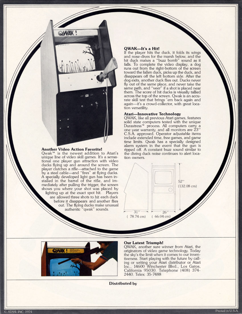
The arcade got its video light gun in 1974. Atari’s Qwak! flyer describes “a sensational one player gun attraction with video ducks flying up and around the screen. The player clutches a rifle—attached to the game by a steel cable—and ‘fires’ at flying ducks.” The important sentence is the next one: “A specially developed light gun has been installed in the barrel of the rifle, and immediately after pulling the trigger, the screen shows you where your shot was placed by lighting up at the exact spot hit.”5
A gun that can show where it was pointed is doing more than detecting a target. It is locating its own aim point on the screen, which means measuring when the beam passed under the barrel. That is the timing method of §2.8, in a coin-op cabinet five years before Baer’s own precision rifle.
The rest of the flyer is a description of a game every reader already knows. Players get “three shots to hit each duck”; a hit duck “folds its wings and nose-dives for the marsh below”; “a dog runs out from the right-bottom of the screen toward the fallen duck, picks up the duck, and disappears off the left bottom side”; ducks “‘veer’ if a shot is placed near them”; and the cabinet carries “a specially designed alarm system in the event that the gun is ripped off”.5 Ten years later Nintendo’s Duck Hunt had the dog, the duck that dives, and the three shots.
The flyer mattered a decade later in court. When Magnavox and Sanders’ licensing agent sued Nintendo over its video-game patents, Nintendo answered in 1986 with a claim that Baer’s precision-rifle patent had been obtained by fraud, “the basis for their assertion” being “a report I made on an Atari Qwak! arcade game at the 1974 MOA show in Chicago”. In Baer’s words, “Nintendo claimed that I had merely reinvented what” he had seen there.1 The outcome is not recorded in the material read for this dive.
2.7 A rifle input on one chip: the AY-3-8500 family
The light gun reached the general toy market through a single integrated circuit. General Instrument’s AY-3-8500 “Ball & Paddle” chip (and the AY-3-8500-1 for 525-line television) put six games on one 28-pin package — tennis, soccer, squash, practice and two rifle games — and it became the heart of most of the cheap pong consoles of 1976–1978.6
The rifle was two pins. Pin 26, Shot Input, “is driven by a positive pulse output of a monostable to indicate a ‘shot’”. Pin 27, Hit Input, “is driven by a positive pulse output of a monostable which is triggered by the shot input if the target is on the sights of the rifle”. In Rifle Game 1, “a large target … bounces randomly about the screen. A photocell in the rifle is aimed at the target. When the trigger is pulled, the shot counter is incremented and, if the rifle is on target, the hit counter is incremented, a hit noise is generated and the target is blanked for a short period. After 15 shots the score appears.”6
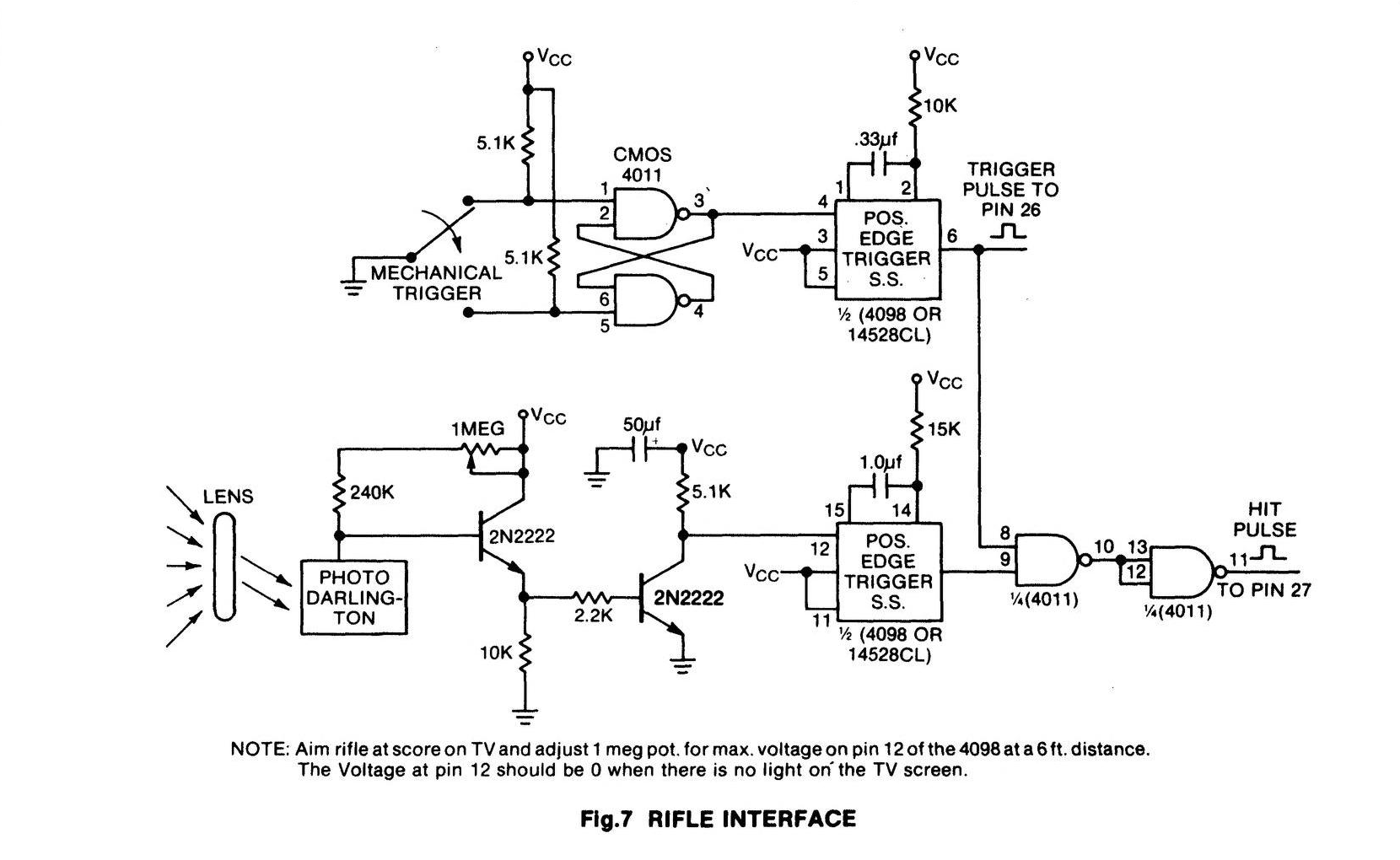
GI’s reference circuit is an instructive half-step beyond the Odyssey. The photo-Darlington is fast enough to follow the field-rate pulses of the target, and it drives an edge-triggered one-shot, so the gun responds to the rising edge of light rather than to its level; and the hit is the logical AND of that light pulse with the shot window. It still has a sensitivity pot to set by eye — “Aim rifle at score on TV and adjust 1 meg pot. for max. voltage on pin 12 of the 4098 at a 6 ft. distance. The voltage at pin 12 should be 0 when there is no light on the TV screen.”6 — and nothing in the circuit stops a flickering lamp from producing edges. But it is a gun designed around the flicker of a CRT, which is the direction the whole 1980s went.
2.8 Baer’s precision rifle, 1979: reading the raster
The fullest statement of the timing method came, again, from Sanders. Baer wanted a rifle for military marksmanship and police “shoot or don’t shoot” training against videotaped scenes, and the old methods would not do:
“The simple, actually crude, methods for shooting at TV screens that we had used in our original light guns for our early videogames wouldn’t do for precision targeting. These older schemes generally depended on either a large, visible white dot target or one that came up briefly after a trigger pull and was basically invisible to the human eye. What we needed now was a way to tell us which scan line and exactly where along that line we were sighting our weapon. Since there are roughly 250 horizontal scan lines in each field … That called for a precision of better than half a percent. … We settled for a response time from the photo sensor and its amplifier of a couple of microseconds, or about three to four percent accuracy since a horizontal TV line is about 60 microseconds long.”1
It worked in September 1979, built into “the pump action BB gun” and running with an Apple II modified to run interlaced and gen-locked to the videotape.1 The patent, US 4,395,045, “Television Precision Target Shooting Apparatus and Method” (filed 16 June 1980, granted 26 July 1983), summarises the method in its abstract: it works “by flashing the screen white subsequent a trigger pull in order that a photosensor within the gun will be responsive to short segments of horizontal raster lines such that by counting vertical lines and time intervals with respect to vertical and horizontal synchronization pulses, respectively, identification of where on the screen the gun was pointing is achieved, permitting a symbol to be displayed upon the screen at that location”.7
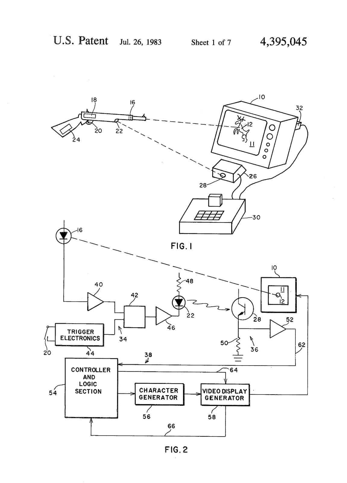
Two features in the drawing reappear a decade later in consumer products. The flash-white-after-trigger method is how almost every 1980s and 1990s console gun located its aim. And the gun talks to its receiver over an infrared link, with no cable — exactly the arrangement of Nintendo’s Super Scope and Sega’s Menacer in 1992 (Volume 4).
Baer’s numbers are still the right ones to remember. A 525-line field has about 240 to 250 visible lines, so knowing the line puts the vertical aim to within half a percent of the screen height. A line lasts about 63.5 µs, of which about 52 µs is picture, so a sensor-plus-amplifier delay uncertainty of 2 µs is about 4 % of the width. Horizontal resolution is set by the speed and consistency of the photodetector chain; vertical resolution is free. That asymmetry runs through every CRT gun in Volumes 3 to 5.
2.9 Three ways to know you hit
By 1980 all three detection schemes that television light guns would use had been built and published:
Table 1 — By 1980 all three detection schemes that television light guns would use had been built and published
| Scheme | How the gun knows the light is the target | First shown | Defeated by | Used later by |
|---|---|---|---|---|
| Level | More light than a threshold in the barrel’s field of view | Sanders 1967; Odyssey 1972 | Any bright source: lamp, window | Nothing after the 1970s |
| Coded or flashed | The target appears, or blinks in a pattern, only when the gun is asked to look | Sanders odd/even quiz gun 1967–68 | A source that happens to flash in step, rarely | Nintendo Zapper (Vol 3) |
| Timed | Light arrives at the moment the beam scans the aimed spot, counted from sync | Qwak! 1974 (shot position shown); Baer precision rifle 1979, US 4,395,045 | Very little; needs a raster | Light Phaser, Super Scope, Menacer, Justifier, GunCon (Vols 3–5) |
The timed method is the strongest and it has one requirement: a raster that draws the picture point by point at a known time. When that requirement disappeared, so did the method (Volume 6).
2.10 What could not be verified
- The outcome of Nintendo’s 1986 declaratory-judgment action against Baer and Magnavox’s lawyers.
- The patent number of Baer’s blue-filter light gun (a phototransistor behind blue acrylic that responded only to blue targets, because of the blue phosphor’s luminous efficiency), which his book says issued “a couple of years” after filing. Not identified.
- Who built Qwak!‘s gun electronics. Secondary sources credit Atari’s Cyan Engineering; the flyer says only “specially developed”.
- The commonly quoted figure of about 20,000 Odyssey rifles sold. No primary source found.
Sources
Footnotes
-
Ralph H. Baer, Videogames: In the Beginning (Springfield, NJ: Rolenta Press, 2005), including the reproduced lab-notebook chronology and the chapters on TV Game #6 and #7, the Magnavox launch, “The Precision Rifle Story” and “The Nintendo Lawsuit Interlude”. Internet Archive item
VideogamesInTheBeginningRalphH.Baer, read 2026-10-19. ↩ ↩2 ↩3 ↩4 ↩5 ↩6 ↩7 ↩8 ↩9 -
Ralph H. Baer, “Recording CRT Light Gun and Method”, US Patent 3,599,221, filed 18 March 1968, granted 10 August 1971, assignee Sanders Associates, Inc. https://patentimages.storage.googleapis.com/pdfs/US3599221.pdf, read 2026-10-19. ↩
-
Ralph H. Baer, “Television Gaming and Training Apparatus”, US Patent 3,728,480, filed 22 March 1971 (continuation of Ser. No. 697,798, 15 January 1968), granted 17 April 1973, assignee Sanders Associates, Inc. https://patentimages.storage.googleapis.com/pdfs/US3728480.pdf, read 2026-10-19. ↩ ↩2
-
The Magnavox Company, Odyssey Shooting Gallery instructions and game rules, © 1972. Internet Archive item
Shooting_Gallery_1972_Magnavox_US, read 2026-10-19. ↩ ↩2 ↩3 ↩4 -
Atari, Inc., Qwak! sales flyer, © 1974, back page. The Arcade Flyer Archive, https://flyers.arcade-museum.com/videogames/show/803, read 2026-10-19. ↩ ↩2
-
General Instrument Microelectronics, 1977 Data Catalog, AY-3-8500/8500-1 and AY-3-8550/8550-1 “Ball & Paddle” data sheets, including Fig. 7 “Rifle Interface”. Internet Archive item
bitsavers_gidataBook_42027291, read 2026-10-19. ↩ ↩2 ↩3 -
Ralph H. Baer, “Television Precision Target Shooting Apparatus and Method”, US Patent 4,395,045, filed 16 June 1980, granted 26 July 1983, assignee Sanders Associates, Inc. https://patentimages.storage.googleapis.com/pdfs/US4395045.pdf, read 2026-10-19. ↩
Comments (0)