SA80 (L85 Family) · Volume 6
Field Strip, Maintenance and Repair
The maker's 1985 drills for loading, unloading, stripping and assembly; the cleaning regime and its 200-round gas-parts rule; immediate action and the gas stoppage; what the armourer did; and what an owner of any SA80-pattern rifle should take from it
6.1 What this volume covers
The SA80’s history (Volumes 2 and 3) turns repeatedly on maintenance: the government’s 1993 view that Gulf War stoppages were “largely attributable to incorrect maintenance”, Ferguson’s view that the 2002 Afghan problem “appears to have been down to a cleaning issue”, and his observation that the A2 is reliable “provided that the fairly detailed cleaning instructions are followed”.12 This volume sets out what those instructions were, in the maker’s words, and what can and cannot be said about the Army’s.
6.2 Which manual
Two kinds of manual exist for the SA80, and only one was found.
The British Army’s pamphlets were not found. Searches of the Internet Archive’s metadata for SA80, L85A1, L85A2, L86A1, L98A1, L98A2, SUSAT and “Enfield Weapon System”; of released UK Air Publications and Air Cadet Publications; of MoD freedom-of-information disclosures; and of the UK Historic Arms Resource Centre turned up no Army pamphlet for any SA80 variant on 18 October 2026. One web page purporting to give the L98A2’s safety precautions was an automatically generated search-optimisation page and is not used. The British Army’s skill-at-arms pamphlets are not published, and this volume does not reconstruct them.
The maker’s User Handbook was found. Royal Ordnance’s 5.56mm Enfield Weapon System User Handbook, copyright 1985, survives in facsimile from the Royal Armouries’ Pattern Room collection. Its contents run: Technical Data; Introduction; Assemblies; Accessories and Spares; Operation, Sights and Handling; Stripping and Assembling; Cleaning; Settings and Adjustments; Functional Failures.3 It describes the IW and LSW as accepted, before the A1’s in-service modifications. Its drills are therefore those of 1985. The mechanism they apply to is the same in the A2 and A3 (Volume 5), and the stripping sequence follows from the mechanism, but the Army has revised its own drills since, most recently in 2025.
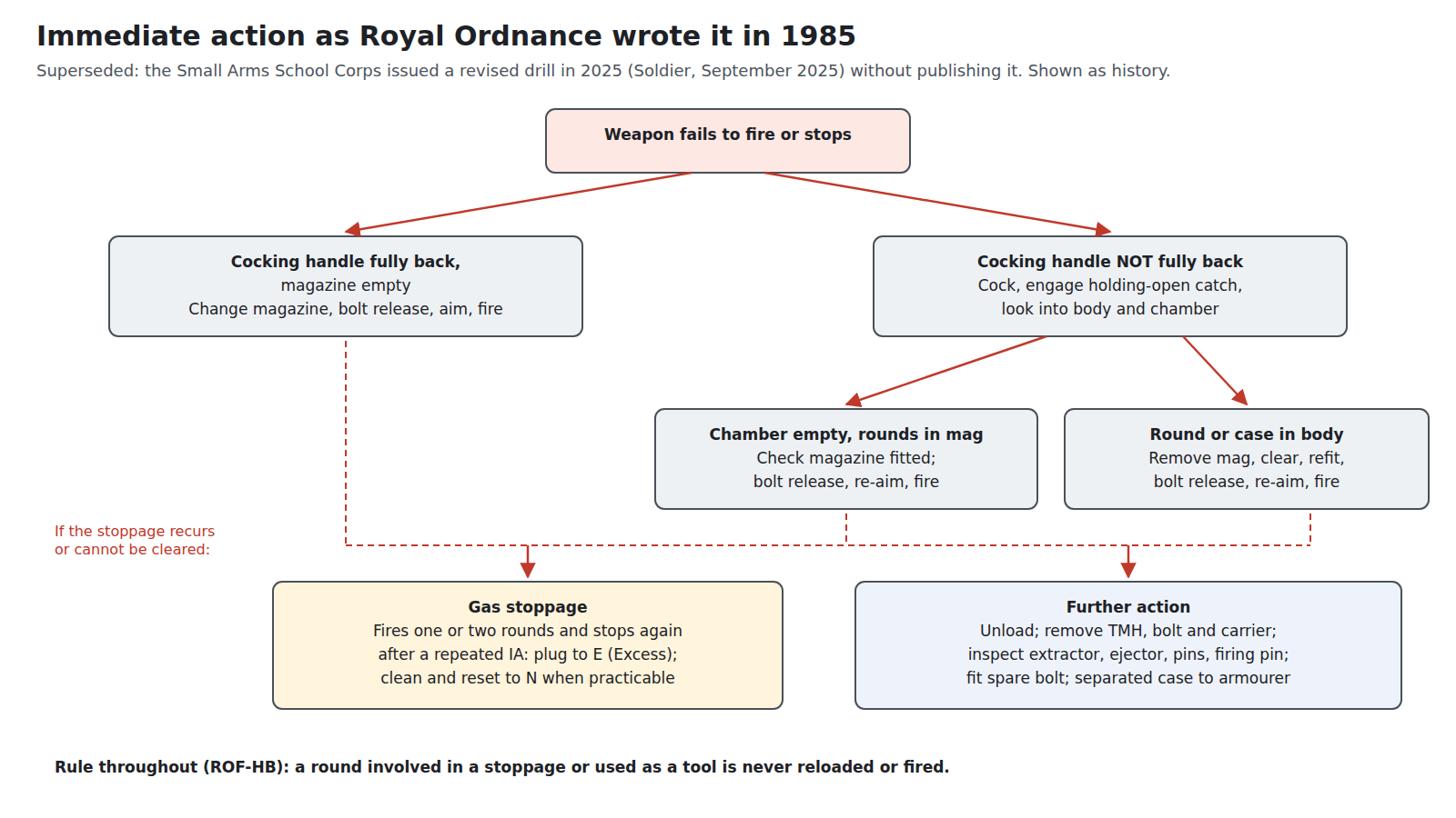
Everything below in quotation marks is the 1985 handbook unless another source is given. Its stripping photographs (Figs. 15–20) and tool drawing (Fig. 21) are Royal Ordnance copyright and are not reproduced; the flow charts here are own work from the text.
6.3 Load, ready, unload
The handbook’s definitions are worth having exactly, because the later drills depend on them: “The weapon is loaded when a magazine is inserted. It is ready to fire when it has been cocked and a live round is in the chamber. It is unloaded when the magazine has been removed and there is no round in the chamber.”
Load. Safety catch to S; change lever to R; “Tilt the weapon to the right and insert a full magazine. Ensure the magazine is clicked fully home”.
Ready. Check the lever is at R; “Pull the cocking handle fully to the rear, then release forward. Do not assist the lever forward or a stoppage may occur.” Safety to F.
Unload. Finger outside the trigger guard, safety to S; check R; remove the magazine — “THIS MUST BE DONE BEFORE CONTINUING”; cock carefully “to prevent the round ejecting too far”, engage the holding-open catch, and inspect the body and chamber (“At night, check the body and chamber are clear by inserting a finger”). Then the bolt release; safety to F and operate the trigger; safety to S; close the dust cover.
The order of the unload — magazine out before the cocking handle is touched — is universal good practice; on a bullpup it matters more than usual, because the magazine is behind the grip and out of sight of a firer looking along the rifle.
6.4 Before stripping
“Do not operate the trigger, do not close the dust cover. The safety catch must remain on ‘S’ and the hammer must remain cocked throughout the time that the weapon is in a stripped state.” The rifle is made safe (S, R), cocked, the holding-open catch engaged, body and chamber checked clear, and the parts let forward with the bolt release. The sight stays on: “Only remove the sight if it cannot be properly cleaned in situ.”
6.5 Field strip, assembly by assembly
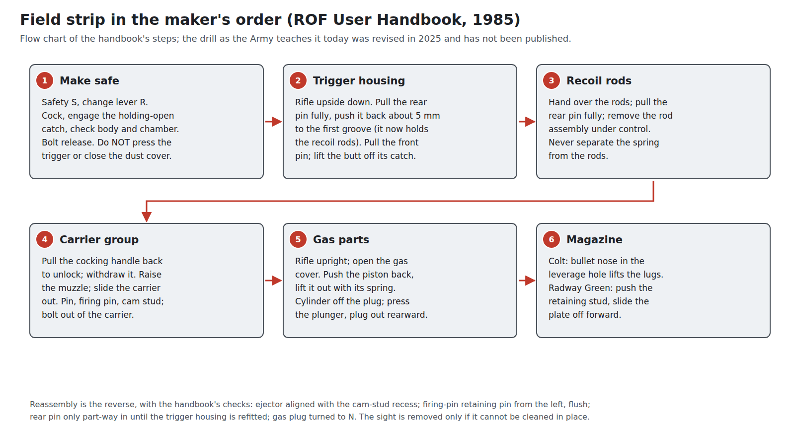
1. Trigger mechanism housing. Weapon horizontal and upside down. “Fully withdraw the TMH rear locking pin, note the grooves on the pin then re-insert the pin approximately 5mm into the body, so that the groove nearest to the body is flush with the outside of its housing (a distinct click should be heard). This ensures that the end of the pin retains the recoil rod assembly while the TMH is being removed.” Then withdraw the forward locking pin and separate the housing “by pulling the butt upwards and disengaging the TMH from its front catch”.
The half-inserted rear pin is the detail most often missed. Without it the recoil rods, under spring load, come free as the housing is lifted.
2. Recoil rod assembly. “Place a hand over the rear of the recoil rod assembly, fully withdraw the TMH rear locking pin then, under control, remove the recoil rod assembly. Do not separate the spring from the [rods].”
3. Bolt carrier assembly. Pull the cocking handle back to unlock the bolt and withdraw the handle from the carrier. With a hand over the rear of the body, raise the muzzle and slide the carrier out. Remove the firing-pin retaining pin, “using the combination tool if necessary”, and withdraw the firing pin from the rear. “Pull the bolt fully forward in the carrier and remove the cam stud. Separate the bolt from the carrier.”
4. Gas system. Weapon upright; open the top cover of the handguard. Grip the cylinder, push the piston rearward against its spring, move it out of line and withdraw the piston with its spring (“Do not separate the spring from the piston”). Pull the cylinder rearward off the plug. Press the plunger on the front of the plug and withdraw the plug “from the rear of the gas block”.
5. Magazines. Colt pattern: insert a bullet nose into the “leverage hole” to lift the locking lugs and slide the floorplate off. Radway Green pattern: “Push in the retaining stud and slide off the bottom plate in the direction of the forward edge.”
6.6 Assembly and the function test
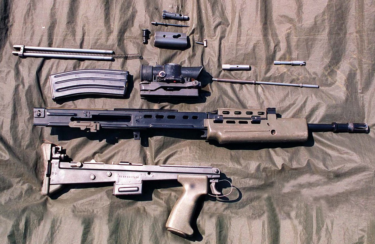
Assembly is the reverse, with checks at each step.
- Bolt into carrier. Align the ejector on the bolt with the cam-stud recess in the carrier; insert the bolt and align the cam-stud hole; insert the cam stud with its firing-pin hole aligned; insert the firing pin from the rear; fit the retaining pin from the left side, flush.
- Carrier into body. With the weapon upside down, push the carrier forward until its cocking-handle recess aligns with “the cocking guide in the body”; insert the handle “through the side of the body”; push forward “until the locking splines on the bolt have entered and locked into the barrel extension”.
- Recoil rods. Into the holes in the rear of the carrier, flush with the end of the body; push the rear pin in far enough to hold them “but not sufficient to obstruct the centre area which accommodates the lug of the TMH”.
- TMH. Front end into “the catch behind the hand guard”, raise the butt, press together; rear pin fully in, then the front pin.
- Gas parts. Plug in from the rear of the block and rotated until the plunger aligns with “N”; cylinder on the rear of the plug; feed the spring end of the piston into the central hole above the barrel extension, compress, and engage it with the recess in the cylinder. A 2026 article notes that the cylinder and piston “could still be installed backward on the A2”; check the orientation against the parts as removed.4
- Function test. “Test the action by cocking the weapon and engaging the holding open catch, then operate the bolt release”, set the safety, and operate the trigger. (The extracted text of this step reads “set the safety catch to ‘R’”, an evident misprint for the change lever.)
6.7 Operational stripping
In the field the handbook allows partial stripping: “one assembly at a time”. Two specific permissions: “The gas assembly may be stripped provided the weapon is unloaded and the bolt carrier assembly is held to the rear. The TMH may be removed without removing any other part.” The gas parts, which foul fastest, can therefore be cleaned without taking the rifle apart.
6.8 Detail strip: what the user may not do
The handbook’s user strip stops at the assemblies above: bolt, cam stud, firing pin and retaining pin out of the carrier; gas plug, cylinder and piston out of the block; magazine floorplate off. It gives no user procedure for the trigger mechanism (hammer, sears, safety sear, trigger bar), the extractor and ejector on the bolt, the recoil-rod spring (which it forbids separating), the SUSAT, or the barrel. A separated case in the chamber is to go to “an armourer”.
The armourer’s instructions — detail stripping of the TMH and bolt, gauging, barrel removal from the barrel extension, the dimensions and tolerances that decide whether a part is serviceable — are in British Army technical publications that were not found. This volume does not supply a detail-strip sequence for the fire control or the bolt; none could be sourced. What any correct procedure has to account for, from the mechanism in Volume 5:
- the safety sear and interceptor sear share the trigger’s axis pin, so the trigger, safety sear and interceptor come out as a group around one pin;5
- the barrel screws into an extension welded into the body, so barrel removal is a workshop job needing a body fixture, not a field task;6
- the extractor and ejector are spring-loaded on the bolt head, with an extractor insert and, on the A2, an ejector spring guide and a solid-stock retaining pin;2
- the recoil rod assembly is a captive spring assembly the user is told not to dismantle.
6.9 Tools and the tool roll
The handbook lists the user’s kit (Fig. 21):
- Cleaning rod, in three sections; “Two sets of rods needed to clean full barrel length”; to be twisted clockwise only.
- Bore brush, and a chamber/barrel-extension brush, “Only to be used for cleaning the chamber, the barrel extension or interior of the gas block”, with the rod only.
- Pullthrough, to be “unravelled and stretched to remove any kinks” before use.
- Swabs, “the optimum size for the purpose, any larger than 43 x 43mm will jam the barrel”.
- Nylon pad (Scotchbrite) and brush, for carbon and, with oil, for rust; it “Must not be used on weapon parts coated with a protective finish as the pad will remove the finish.”
- Combination tool, “used when cleaning the weapon, fitting and adjusting the sights, and adjusting the gas system”: scrapers for the gas vent, plug and regulator, a screwdriver and a sight spanner.
As a spare, “A complete Bolt Carrier Assembly, including firing pin, may be included in the tool roll.” The brochure claimed that “No special tools are required.”6
6.10 Cleaning
The handbook’s sequence, in eleven steps:
- Unload and strip.
- Nylon brush to remove loose fouling and debris.
- A lightly oiled swab over the outside.
- Chamber/barrel-extension brush on the rod, into the chamber, “With a clockwise rotating action”.
- Nylon brush and swab inside the body.
- Bore brush through the barrel, then pullthrough and dry swabs.
- “Carbon fouling is removed with the combination tool scrapers and the nylon pad. Wipe clean the piston, gas cylinder and gas plug, then lightly oil.”
- Dry clean the whole weapon.
- “Lightly oil the weapon and magazine, but not the SUSAT or Iron Sight apertures and post.”
- “Assemble the weapon and test for correct functioning.”
- SUSAT: clean the bracket with nylon brush and oily swabs, “ensuring no oil gets on the rubber eye piece or lens”; dry the exterior; lens cloths for the lens; “lightly oil the shoe, then refit the sight.”
And the rule that matters most: the gas parts “should be cleaned and gauged, using the combination tool scrapers, after every 200 rounds fired, regardless of satisfactory functioning of the system.” It sits in the Functional Failures section, not the cleaning section, which may be why it was missed in units whose stoppages the government later blamed on “incorrect maintenance” (Volume 2).
Two hundred rounds is a short interval. It is about seven magazines; a soldier on a range day fires more. The gauging is done with the scrapers of the combination tool, which have profiles for the plug, the vent and the regulator. Ferguson’s remark that the A2 is reliable “provided that the fairly detailed cleaning instructions are followed” reads differently once this interval is known.2
6.11 Lubrication
The handbook’s lubrication instruction is the single word “lightly”: the weapon and magazine “lightly” oiled, the gas parts “lightly” oiled after cleaning, nothing on optical surfaces or iron-sight apertures. It names no oil, gives no chart of points, and sets no interval other than “after cleaning”. The government’s 1993 response to the Defence Committee said “Some units had not been employing the correct lubrication and cleaning procedures”, which implies a defined procedure existed in the Army’s own publications by then; it was not found.1
6.12 The blank-firing attachment
The blank-firing attachment (BFA) is a choke tube on the muzzle. The handbook’s fitting instruction: screw the choke tube in by hand until it butts on the muzzle, then a further 180° with the combination tool “to stretch the attachment body”. Gas leakage past a loose BFA causes “short recoils” — the parts not travelling far enough to feed. The SureFire flash suppressor fitted to some A2s was withdrawn partly because it was incompatible with the issue BFA.2 The yellow BFA is visible in several photographs in Volume 2.
6.13 Immediate action, 1985
The handbook’s immediate action (IA), “If the weapon fails to fire, or stops firing”:
- If the cocking handle is fully to the rear and the magazine empty: change magazine, operate the bolt release, aim, test and adjust, continue firing.
- If the cocking handle is NOT fully to the rear: cock, engage the holding-open catch, look into the body and chamber.
- Chamber empty and rounds in the magazine: check the magazine is correctly fitted, bolt release, re-aim, test and adjust, continue.
- Live round or empty case in the body or chamber: remove the magazine, clear the obstruction, replace the magazine, bolt release, re-aim, test and adjust, continue.
- “It is important that any round which has been involved in a stoppage or used as a tool whether it appears damaged or not, is not to be loaded into a magazine or any attempt made to fire it.”
“Used as a tool” refers to the drill for removing a Colt magazine’s floorplate with a bullet nose.
6.14 The gas stoppage
“If, after carrying out the IA, the weapon fires one or two rounds and then stops again, and, after repeating the IA the same condition arises —
- Operate the bolt release, put the safety catch to ‘S’ and, using the combination tool, turn the gas plug so that the plunger engages the ‘E’ (Excess) gas setting.
- Place the safety catch to ‘F’, aim, test and adjust, continue firing.
- As soon as is practicable the gas assembly must be cleaned and reset to the ‘N’ (Normal) setting.”
The excess setting is a field remedy for a fouled system, not a standing adjustment. A rifle left on E runs harder and fouls faster.
6.15 Further action and the armourer
“If an obstruction in the chamber cannot be removed during the IA, or obstructions occur repeatedly, or the weapon will not fire after carrying out the IA”:
- Unload and remove the TMH, bolt and carrier.
- Inspect the extractor, ejector, retaining pins, firing pin and chamber.
- If bolt parts are damaged or loose, fit the spare bolt assembly.
- If a damaged extractor has left a case in the chamber, fit the spare bolt, cock so the new extractor grips the case, and extract it.
“If the chamber does not appear obstructed and there are no damaged parts, examine the chamber and if there is a separated case — refer the weapon to an armourer.” That sentence, and the parts the handbook tells the user to inspect, map the A1’s known weak points: extractor, ejector, pins, firing pin.
6.16 The 2025 drills
In September 2025 the Army’s magazine Soldier reported that the Small Arms School Corps had “rolled out a series of changes to weapon handling procedures, marking the most significant evolution in SA80 practices since its introduction 30 odd years ago”. The changes it listed include a “Revised immediate action drill”, “Removal of the tap forward assist”, “Updated weapon handling tests”, a “high ready” position replacing the standing alert, post-firing checks integrated into the basic drills, finger placement and trigger operation taught in the first lesson, the “Deletion of the make safe drill”, and new close-quarter positions.7
The article does not give the new drills. The 1985 drill above, and the Army’s pre-2025 drill with its “tap forward”, are both superseded; neither should be presented as current. The deleted “tap forward” was the descendant of the brochure’s statement that the cocking handle “can be used to push home the breech assembly” (Volume 5).6
6.17 Parts that wear and parts that broke
The sources give no wear intervals for the A2 and no published barrel life. What they do give:
Table 1 — The sources give no wear intervals for the A2 and no published barrel life. What they do give
| Part | Evidence | Source |
|---|---|---|
| Gas plug, cylinder, piston | Clean and gauge every 200 rounds; plug reinforced and cylinder remade in the A2 | ROF handbook; ARES 5 |
| Firing pin | Tip breakage; reprofiled in the A2 | ARES 5 |
| Extractor, ejector, pins | Listed for inspection in further action; claw enlarged, ejector given a spring guide, pin made from solid stock in the A2 | ROF handbook; ARES 5 |
| Bolt carrier assembly | Carried complete as a spare in the tool roll | ROF handbook |
| Trigger return spring | Broke on a marksman at Bisley, 1990 | Hansard (Lord Lyell) |
| Magazine catch | Accidental release; shroud added 1987 | ARES 4 |
| Furniture | Early green plastic broke; replaced | ARES 5 |
| Radway Green magazine | ”A new weak point”; replaced by the H&K steel magazine | ARES 4, 5 |
| Barrel | 4.85 mm prototype barrels gave “only 3,000 rounds”; XL70 barrel wear blamed on “poor metallurgy and a lack of chrome lining”; A2 barrel in “higher grade steel” | ARES 2, 3, 5 |
| Springs | All remanufactured in the A2 | ARES 5 |
No source found states whether the A2 barrel is chrome-lined; the XL70 finding is the only statement on chrome. Barrel life for the service rifle is not published.
6.18 Repair and parts for a civilian owner
No service SA80 is in civilian hands in the United States (Volume 9), so “repair” for an American owner means one of three things: a US-made semi-automatic SA80, an AR-based lookalike, or an airsoft replica. The lessons of this volume transfer to the first.
- The gas parts are the maintenance item. Any rifle built on the SA80’s plug-and-moving-cylinder system will foul in the same place. Clean and inspect them on the maker’s interval; the 1985 handbook’s 200 rounds is the only published one.
- Springs. Murdoch & Co., which makes a US semi-automatic SA80, advertises “Use of modern common springs for maintenance” on its Collector rifle, which implies that its springs are commercial rather than proprietary.8
- Magazines. STANAG-pattern magazines fit. Murdoch’s own compatibility list excludes “Any non standard magazines with a front and rear spine support shelf”, and lists the British H&K magazine, the British E-Mag and several American steel and polymer magazines as compatible.9 A US dealer in replica furniture lists surplus British H&K steel 30-round magazines at $95.10
- Bolt, carrier, extractor, firing pin, gas parts. No US supplier of SA80 internal parts was found. Owners of a US-made SA80 depend on its maker. Military parts are not available: the Ministry of Defence’s policy is that “all weapons are disposed of by being destroyed”, and a demilitarised parts trade like the one that supplies STEN and Sterling builders does not exist (Volume 9).11
- Gunsmith or maker. Anything beyond the user strip — the fire control, extractor and ejector replacement, barrel work in the welded extension — belongs with the maker or a gunsmith working from the maker’s information. No published armourer’s data was found.
6.19 Corrections this volume makes
- No British Army SA80 pamphlet is available online; the only verbatim drills are the maker’s 1985 handbook.
- The gas parts were to be cleaned and gauged every 200 rounds “regardless of satisfactory functioning” — a maker’s rule printed in the handbook’s failures section.
- The “tap forward assist” was removed from Army drills in 2025, along with the make-safe drill; the IA was revised and not published.
- The user strip does not go into the trigger mechanism; detail stripping was armourer-level, and no armourer’s procedure was found.
- The handbook’s function-test step contains a misprint (“safety catch to ‘R’” for the change lever).
References
Footnotes
-
House of Commons, “Defence White Paper”, 28 February 2000, Mike Hancock quoting the government’s response to the Defence Committee. https://hansard.parliament.uk/Commons/2000-02-28/debates/7daf85df-c7e8-446c-b3b5-b073d71464ca/, consulted 2026-10-18. ↩ ↩2
-
Jonathan Ferguson, “British Enfield SA80 Part 5: SA80 A1 vs A2”, The Hoplite, 20 May 2017. Wayback capture of 28 May 2017, http://web.archive.org/web/20170528111515/http://armamentresearch.com:80/british-enfield-sa80-part-5-sa80-a1vsa2/, consulted 2026-10-18. ↩ ↩2 ↩3 ↩4
-
Royal Ordnance, 5.56mm Enfield Weapon System: User Handbook, copyright Royal Ordnance plc 1985 (hosted file named 1986): Operation, Sights and Handling pp. 19–39; Stripping and Assembling pp. 41–53; Cleaning pp. 54–56; Settings and Adjustments pp. 57–61; Functional Failures pp. 62–64; Fig. 21. Flip-book hosted by the UK Historic Arms Resource Centre, images courtesy of the Royal Armouries, https://www.rifleman.org.uk/Images/PDF-files/SA80-user-manual/index.html, consulted 2026-10-18. Royal Ordnance copyright; quoted, not reproduced. ↩
-
Lynndon Schooler, “Inside the British L85 Bullpup Rifle”, The Firearm Blog, 21 August 2026, consulted 2026-10-18. ↩
-
Jonathan Ferguson, “British Enfield SA80 Part 2: XL60 series”, The Hoplite (Armament Research Services), 10 May 2017. Wayback capture of 17 January 2026, http://web.archive.org/web/20260117101829/http://armamentresearch.com/british-enfield-sa80-part-2-xl60-series/, consulted 2026-10-18. ↩
-
Royal Ordnance, The Enfield Weapon System (sales brochure, c. 1985). Via the UK Historic Arms Resource Centre, https://www.rifleman.org.uk/Images/PDF-files/Enfield_Weapons_System/index.html, consulted 2026-10-18. ↩ ↩2 ↩3
-
“New rules for SA80”, Soldier, September 2025, Crown copyright, https://soldier.army.mod.uk/issues/september-2025/update/sa80, consulted 2026-10-18 through the shared fetch engine. ↩
-
Murdoch & Co., “EM-85”, https://murdochandco.com/em-85/, consulted 2026-10-18. ↩
-
Murdoch & Co., “EM85A3”, https://murdochandco.com/em85a3/, consulted 2026-10-18. ↩
-
Aly & Kaufman LLC, home page product listings, https://aandk.llc/, consulted 2026-10-18. ↩
-
Gaz Corfield, “Mystery of the L98A1 Cadet GP rifle’s fate”, UK Shooting News, 7 March 2016, quoting an MoD freedom-of-information reply of April 2015, https://ukshootingnews.wordpress.com/2016/03/07/mystery-of-the-l98a1-cadet-gp-rifles-fate/, consulted 2026-10-18. ↩
Comments (0)