SA80 (L85 Family) · Volume 5
How It Works
The bullpup layout, the short-stroke gas system with its moving cylinder, the rotating bolt in a welded barrel extension, three recoil rods, the long trigger bar and the safety sear, described in the makers' own words
5.1 What this volume covers
The SA80 is a gas-operated, rotating-bolt, magazine-fed rifle firing from a closed bolt, arranged as a bullpup. That one sentence fits a dozen rifles. What makes the SA80’s mechanism its own is a handful of details that are usually described wrongly: the gas cylinder moves and the plug does not; there are three recoil rods, not two; the firing pin has no spring; the bolt locks into a barrel extension welded into a pressed-steel body; and a part called the “safety sear” holds the hammer until the bolt is locked. This volume describes each in the makers’ own words, then follows the cycle from trigger to the next round. The automatic setting is described only as the makers described it, in a sentence; this dive carries no select-fire detail.
5.2 The sources
Two Royal Ordnance documents survive in facsimile at the UK Historic Arms Resource Centre, from originals in the Royal Armouries’ Pattern Room collection: the sales brochure The Enfield Weapon System, and the 5.56mm Enfield Weapon System User Handbook, “copyright © Royal Ordnance plc 1985”.12 Both describe the weapons as accepted, before the A1 modifications and long before the A2. They are the maker’s commercial documents, not the British Army’s pamphlet, which was not found (Volume 6). Where Jonathan Ferguson’s ARES series adds lineage or later changes it is cited separately.345 The handbook’s mechanism drawings (Figs. 8A and 8B) are Royal Ordnance copyright and are not reproduced; the diagrams in this volume are own work drawn from the documents’ words.
5.3 The layout
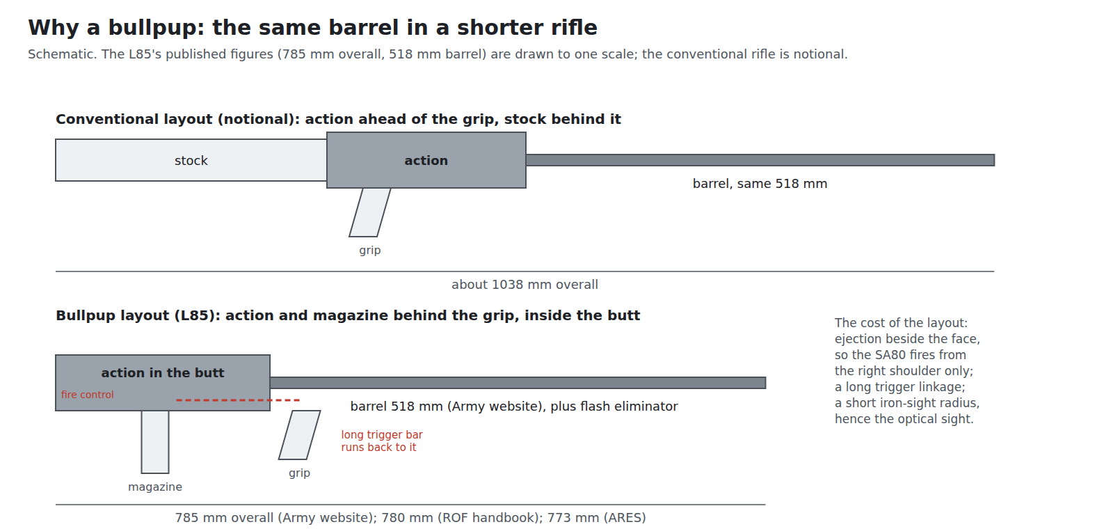
“The 5.56mm Enfield Weapon System comprises the Individual Weapon (IW) and the Light Support Weapon (LSW). Both the IW and the LSW have the same basic components and therefore most are interchangeable … Both weapons use a short stroke gas system and a rotary forward-locking breech mechanism to give single shot or automatic operation from a 30 round magazine.”2 The brochure calls the layout “buttless”: the action sits in what on a conventional rifle would be the butt, the magazine behind the pistol grip, and the firer’s cheek on the body itself.1
The layout explains three features that recur through this dive. A long trigger bar runs back from the trigger to the fire-control group behind the magazine. The ejection port is beside the firer’s face, so the rifle can be fired only from the right shoulder (Volume 2). And the sight radius of iron sights is short, which is why an optical sight was standard from the outset (Volume 8).
5.4 Seven assemblies
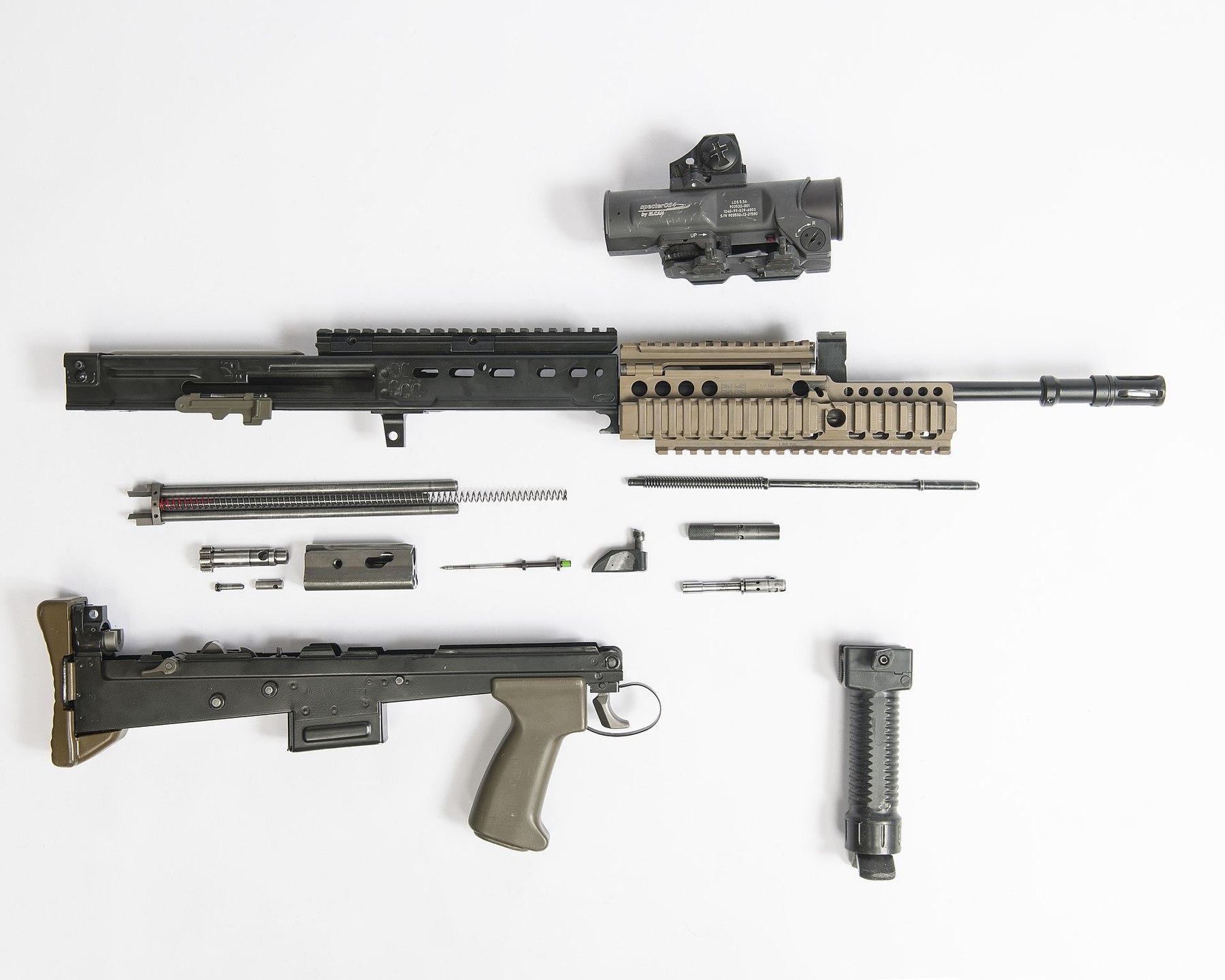
The handbook names the rifle’s major assemblies: “The basic weapon can be stripped down to seven major assemblies”: the magazine, the sights, the trigger mechanism housing (TMH), the barrel–breech assembly, the gas system, the bolt carrier assembly and the recoil rod assembly.2 (The sights count as an assembly because the rifle has no fixed iron sights; Volume 8.) The cocking handle is removed separately during stripping but is not one of the seven.
5.5 The body and the barrel extension
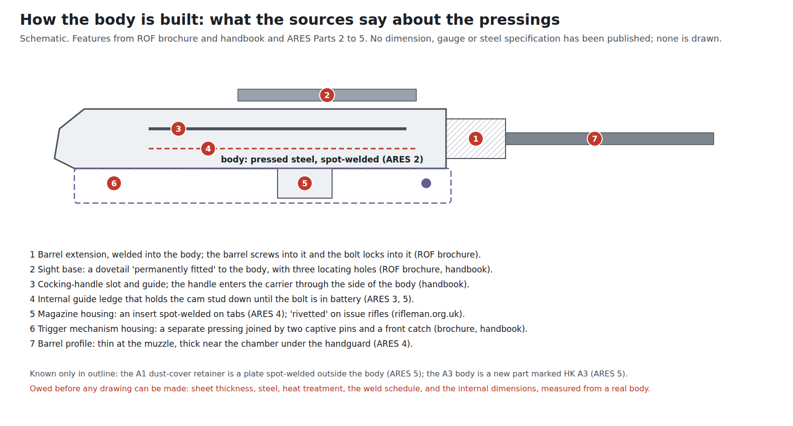
The body is a pressing. “The pressed steel main body houses the breech mechanism assembly and guide rods. The barrel is fixed to the body by screwing into the barrel extension which is welded into the body pressing. The non-metallic handguards are fixed to the body/barrel but have a removable cover for access to the gas system.”1
That arrangement is the opposite of an AR-15’s, where the barrel extension is part of the barrel. On the SA80 the extension, in which the bolt locks, belongs to the body. Ferguson makes the point when listing the A2 changes: the “Barrel extension (part of the body assembly and not the barrel)” was relieved by cutting away “1.5 locking splines”.5 For anyone thinking about building one (Volume 9), it means the locking surfaces sit in a part welded into a sheet-metal box.
The trigger mechanism housing is a second pressing: “The trigger mechanism is a self contained assembly attached to the main weapon body by two captive pins.”1 It carries the fire-control group, the magazine housing, the pistol grip and the butt. The prototypes’ receivers were “of spot-welded pressed (stamped) steel construction”; on the XL80 the receiver was “redesigned in detail, re-toleranced, and the method of welding was changed”, and the magazine housing became an insert spot-welded on tabs on the TMH.36 Inside the body an internal guide rail, changed on the L85A1 from an L-shape to “an oblique angled profile”, runs along the carrier’s path.5 The sight base is a dovetail “permanently fitted to the weapon body”.1
What the sources do not give is any dimension: sheet thickness, steel grade, heat treatment, weld schedule. None was found for this dive.
5.6 The gas system: a fixed plug and a moving cylinder
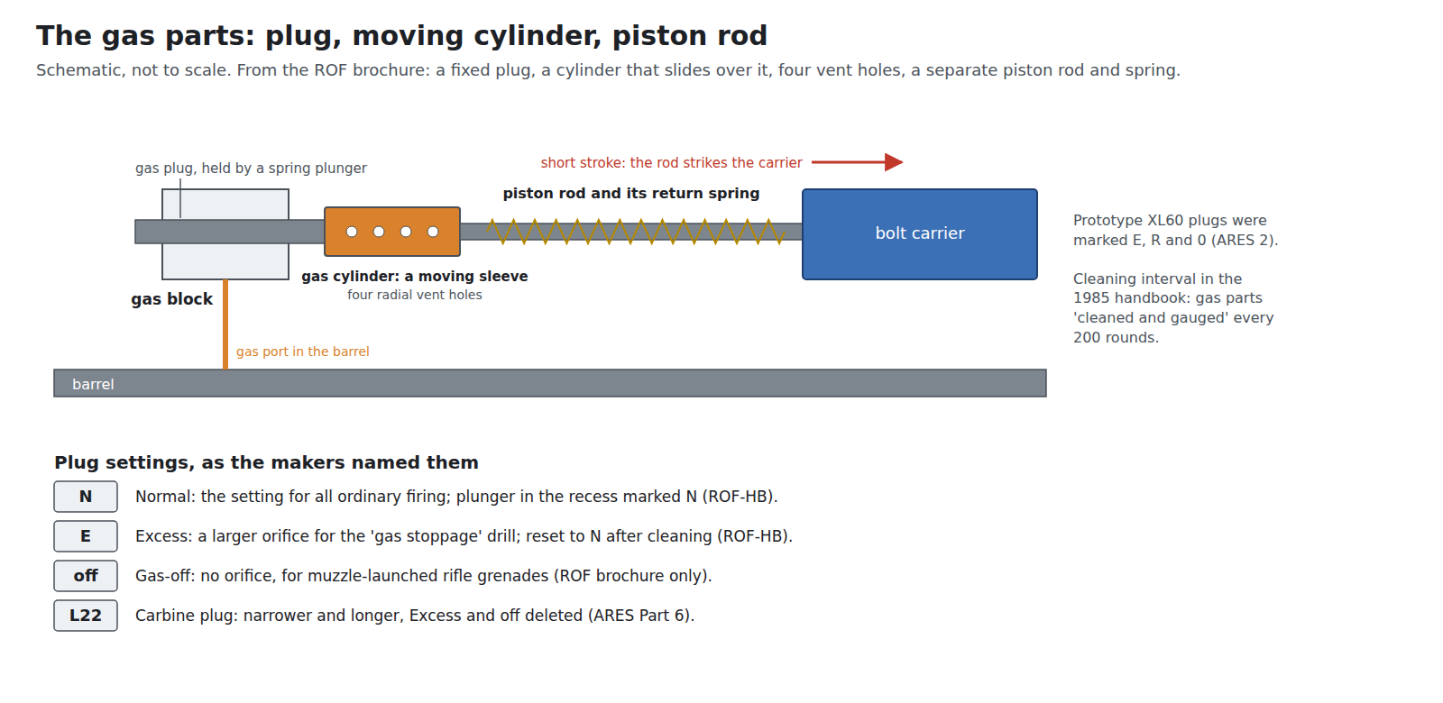
The gas system is the part most often misdescribed, usually as a conventional piston in a fixed cylinder. Royal Ordnance’s brochure describes three parts:1
“Items 2, 3 and 4 form the gas system (short-stroke arrangement). The gas plug (2) is fitted into a hole in the gas block on the barrel — at the front of the handguard cover (1), and is retained by a spring plunger. Gas which is tapped off the bore passes into the gas plug through a small metering orifice.”
“Gas cylinder: When assembled, the gas cylinder forms a sleeve over one end of the gas plug. At the other end a shallow socket locates the piston rod (4). Gasses tapped off the barrel flow down the plug causing the cylinder and piston rod to move the breech mechanism assembly (5) rearwards, four radial holes in the cylinder allow gasses to be vented off after a short travel. The latter now has sufficient energy to complete the recoiling cycle, ejecting the spent case.”
“Piston rod: The piston rod and spring, imparts movement to the bolt carrier. After gasses have been vented, the spring returns rod and cylinder to the position for the next cycle.”
So the plug is fixed in the gas block and acts as the piston; the cylinder is the moving part, a cup sliding back off the plug; four radial holes in it vent the gas once it has moved a short distance; and a separate piston rod, seated in a socket at the back of the cylinder, carries the blow to the carrier. Its own spring returns rod and cylinder. This is the short-stroke principle — the gas parts move a short distance and impart momentum; the carrier completes its travel on that momentum — with the roles of piston and cylinder exchanged.
Ferguson traces the simplification. The AR-18 used a four-piece system; “The XL60 had already simplified the ArmaLite four-piece gas system to three components, without a connecting link”, and “The XL70 took the design another step further from the original, employing a simple tubular gas cylinder”, “hollowed at both ends to accept the piston/gas plug at the front and the rod to the rear”.4 Ferguson’s phrase “piston/gas plug” agrees with the brochure: the plug is the piston.
The arrangement has a practical consequence the handbook spells out. The gas parts foul quickly, and they “should be cleaned and gauged, using the combination tool scrapers, after every 200 rounds fired, regardless of satisfactory functioning of the system”.2 A recent American article notes that the cylinder and piston “could still be installed backward on the A2”, a reassembly error to watch for.7
5.7 Gas settings
The handbook names two settings on the gas block, “N” (normal) and “E” (excess): “Rotate the plug until the plunger is aligned with the recess marked ‘N’ (normal) on the front of the gas block”; the gas-stoppage drill moves the plug to “‘E’ (Excess)” and back to “N” after cleaning.2 The brochure adds a third: “A ‘gas-off’ position (no orifice to allow gas bleed off) is offered for use when muzzle launched grenades are being fired.”1 The handbook does not mention it. “Adverse”, often given online as the second setting’s name, is not the makers’ word.
The prototypes differed. The XL60 “00 series” plug was marked “E”, “R” and “0”: “E is for ‘Excessive’ and ‘Zero’ for launching rifle grenades. ‘R’ is a mystery … As this setting on later patterns is ‘N’ for ‘Normal’, perhaps here it is ‘Regular’.”3 The L22 carbine’s plug has a smaller bore, is longer for “approximately 2.5 mm extra travel”, and lacks the excess and off positions.8 Whether the A2 rifle’s reinforced plug keeps all three of the A1’s positions was not established from a primary source.
5.8 The bolt, carrier and cam
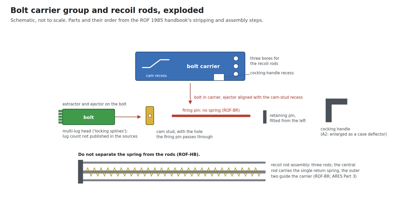
“A multi-lug locking system is used which requires only a small angular rotation of the bolt to ensure effective locking. The breech is unlocked either manually with the cocking handle (6) or by the gas system causing rearward movement of the carrier.”1 The handbook calls the bolt’s lugs “locking splines”, which enter and lock “into the barrel extension”.2 The number of lugs is not given in either Royal Ordnance document or in the ARES series, and no count is printed here.
The bolt rotates by a cam stud that passes through the bolt and runs in a cam stud slot in the carrier. The handbook’s operating sequence: on firing, “The bolt is unlocked by the rearward movement of the carrier forcing the cam stud down the cam stud slot”; on closing, “The bolt is rotated to lock into the barrel extension by the continuing forward movement of the carrier forcing the cam stud to slide up the cam slot.”2 The firing pin passes through a hole in the cam stud and is held by a retaining pin inserted “from the left side of the bolt carrier”, so the pin, stud and bolt are locked to one another by a single cross pin.2
The bolt head was weak from the start. On the XL60 it was “a very weak bolt head … a feature actually borrowed from the Stoner 63 bolt”; the “0 series” reinforced it.3 Extractor and ejector are on the bolt; the handbook’s assembly instruction is to align “the ejector on the bolt with the cam-stud recess in the carrier”.2 The A2 enlarged the extractor claw, gave the ejector a spring guide and lengthened the cam stud (Volume 3).
5.9 The firing pin has no spring
“The firing pin has low inertia, no firing pin spring is fitted. The carrier design makes it impossible to strike the cap of a round with the breech mechanism unlocked.”1 The pin floats in the carrier and is driven by the hammer. Its protection against firing out of battery is mechanical: the carrier’s geometry, and the safety sear described below. The A2 reprofiled the pin “to prevent tip breakage”, which tells its own story about the A1’s pins.5
5.10 Three recoil rods
“Recoil rod assembly: Three rods pass through bores in the carrier. The central rod is a core for the breech mechanism return spring.”1 The handbook’s stripping instruction treats the three rods and the spring as one assembly — “Do not separate the spring from the [rods]” — retained in the body by the TMH’s rear locking pin.2 At the rear of the carrier’s travel is a buffer: “Rearward movement of the carrier and bolt ceases when the rear of the carrier strikes the buffer.”2
The AR-18 had two rods, each with a spring. The change came with the XL70: “The slender twin guide rods and springs taken from the AR-18 were replaced by a stronger (and therefore heavier) triple rod design. This replaced the twin springs with a single spring fitted to the larger central rod, leaving the two outer rods to function simply as bolt carrier guides.”4 Descriptions of the SA80 as having “twin guide rods” describe its ancestor, not the rifle.
5.11 The cocking handle
The handle is a separate part inserted “through the side of the body” into a recess in the carrier, and it reciprocates with the carrier.2 Royal Ordnance’s description: “This is used to cock the weapon manually and to withdraw the breech mechanism to the rear for inspection. Under adverse environmental conditions it can be used to push home the breech assembly.”1 That last sentence is the origin of the “tap forward” assist the Army taught for thirty years, which the Small Arms School Corps removed from the drills in 2025 (Volume 6).9 On the XL70 the handle’s machined locating lug was replaced by “a simple roll-pin (a simple and effective arrangement that persisted into service)“.4
5.12 The fire control: a trigger at the wrong end
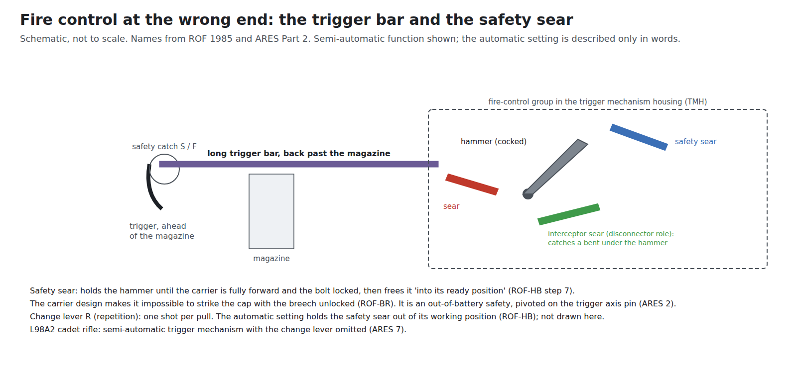
The trigger sits ahead of the magazine; the hammer and sears sit behind it in the TMH. A long trigger bar connects them. Ferguson: “As well as the long trigger bar required by the bullpup arrangement, every component of this assembly is of a different shape and arrangement” from the AR-18’s.3 The safety catch is at the trigger, “operated by the forefinger of the trigger hand”, marked S and F; the change lever on the housing is marked R (repetition) and A (automatic).12
The part that makes the SA80’s fire control unusual is the safety sear. The handbook: “It is not before the parts are fully forward and locked that the safety sear can operate to free the hammer into its ready position. A distinct click will be heard.”2 It is an out-of-battery safety: after the hammer is cocked by the carrier, the safety sear holds it until the carrier is fully forward and the bolt locked, and only then releases it to the trigger sear. Ferguson describes it as “a simpler, more purpose-designed single-piece lever (‘safety sear’) pivoted on the trigger axis pin”. The disconnector function is performed by an “interceptor sear”, which “operates on a bent in the bottom of the cocked hammer”.3
On repetition, the handbook says only that “The safety sear allows one shot only per trigger operation with the change lever at ‘R’.” On automatic, “the safety sear is held out of its working position and automatic fire results.”2 No further description is given here.
The fire control gave trouble from the first trials — “Weapon firing auto when set to single shot; and Trigger not returning to the fully forward position when released”, blamed on dirt and “the very tight fit of parts” — and its triggers went through three patterns (Volumes 1 and 2).36 The A2 reinforced the hammer stop and increased the hammer’s weight.5 The L98A2 cadet rifle has a semi-automatic-only trigger mechanism with no change lever.10
5.13 The cycle, step by step
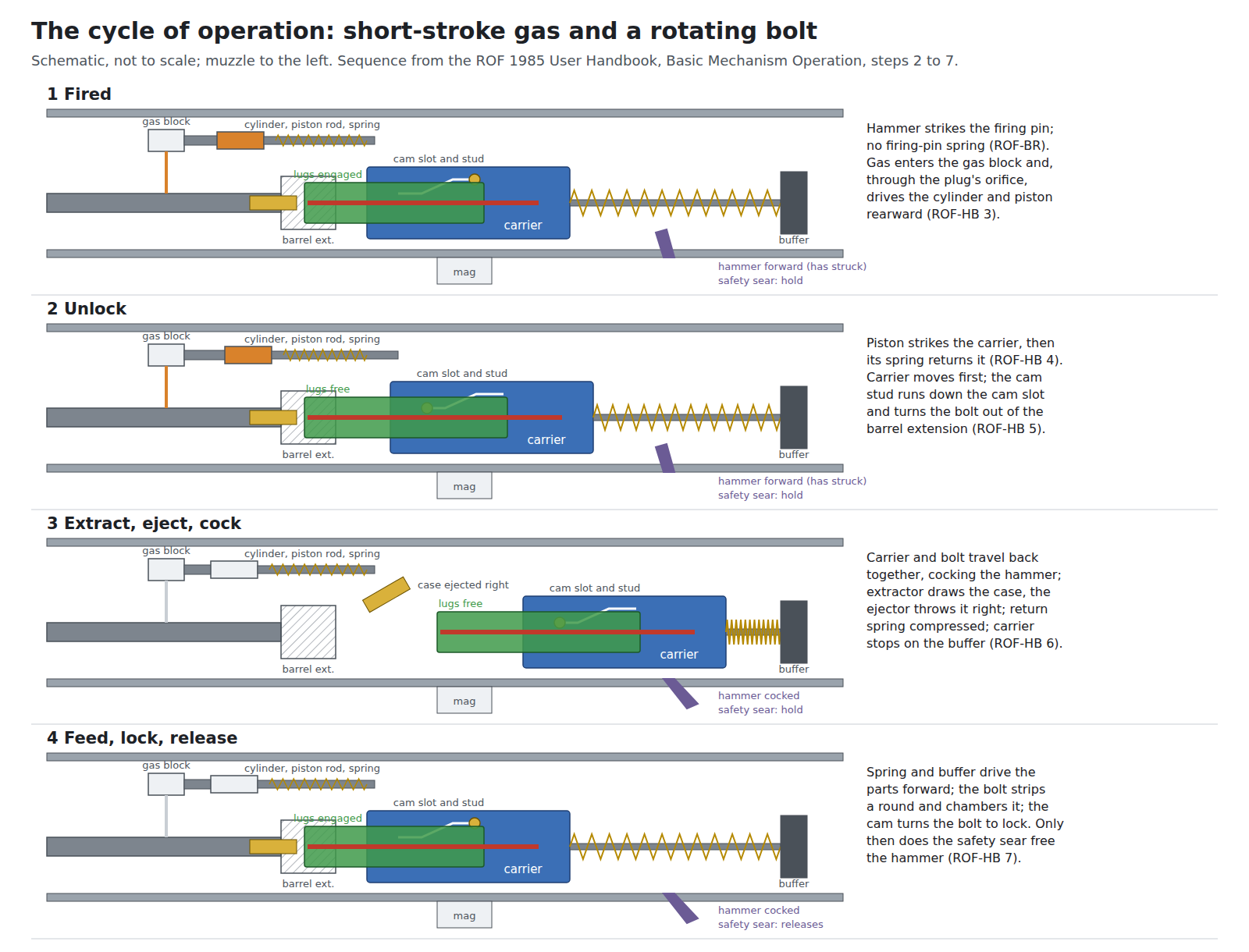
The handbook’s “Basic Mechanism Operation”, for the change lever at repetition, in eight steps. The quotations are the handbook’s.2
- Safe. “When the safety catch is at ‘S’ the trigger cannot be fully operated.”
- Fire. “When the safety catch is at ‘F’ and the trigger is pressed, the hammer is released and hits the rear of the firing pin, driving it forward on to the cap in the base of the round.”
- Gas. “Some of this gas enters the gas block and is diverted by the gas plug into the gas cylinder, driving the piston and spring to the rear.”
- Impulse. “The rear of the piston strikes the carrier, forcing it backwards. The compressed piston spring re-asserts itself and forces the piston forward again.”
- Unlock. “The bolt is unlocked by the rearward movement of the carrier forcing the cam stud down the cam stud slot.”
- Extract, eject, cock. “The carrier and bolt go back together, cocking the hammer as they go. The empty case is withdrawn from the chamber by the extractor and ejected out of the weapon to the right. The return spring on the guide rod is also compressed at this stage. Rearward movement of the carrier and bolt ceases when the rear of the carrier strikes the buffer.”
- Feed and lock. “The return spring re-asserts itself and, aided by the buffer, drives the carrier and bolt forward. As it does so, the bolt feeds the next round out of the magazine and into the chamber. The extractor grips the round and the ejector is compressed. The bolt is rotated to lock … It is not before the parts are fully forward and locked that the safety sear can operate to free the hammer into its ready position.”
- Ready. “The weapon is now ready to fire again”, until the last round, after which “The working parts will then be held to the rear by the holding open catch being lifted up by the magazine platform.”
Step 3 in the handbook is looser than the brochure: it speaks of gas “driving the piston and spring”, where the brochure says the gas moves the cylinder, which pushes the rod. The two descriptions are of the same parts; the brochure’s is the more exact.
5.14 Hold-open and bolt release
“The magazine operates a ‘holding open’ device. After the last round is fired the breech mechanism assembly is arrested at the rear of the weapon … the weapon need not be re-cocked after exchanging the magazines.”1 A bolt-release button lets the parts forward.2 The hold-open can also be engaged by hand, which the unloading and stripping drills use (Volume 6). The A2 extended the “Hold open device carrier and button … for more positive engagement”.5 The bolt hold-open worked by the magazine follower dates from the XL60 “0 series”.3
5.15 The magazine
“This is a 30 round capacity box magazine with the same interface as the Colt 5.56 magazine (M16 fitting). This ensures the weapon can use the wide range of alternative feed systems available with the same interface.”1 The handbook covers two magazines, the Colt and a British Radway Green pattern, with different floorplates.2 The Radway Green magazine was a weak point (Volume 2); the A2 replaced it with a steel magazine “based upon H&K G41 design”, and polymer Magpul magazines followed in service.5 The interface is the one documented in the hub’s AR-15 5.56 dive, Volume 7.
5.16 How much is AR-18
Volume 1 set out the lineage: the 1970 study recommended the AR-18’s gas system, and Enfield converted a Japanese-made AR-18 into a bullpup.11 Ferguson’s judgement on the result is that “the gas system and working parts of the new weapon were very closely based upon an existing and straightforward design; the ArmaLite AR-18”, but that “every effort was made to design an original, British weapon” and the working parts, “despite claims to the contrary, have not been directly copied, and differ in every detail”.3
Set side by side from the sources, the inheritance is the principle and not the parts:
Table 1 — Set side by side from the sources, the inheritance is the principle and not the parts
| ArmaLite AR-18 | SA80 | Source | |
|---|---|---|---|
| Operation | Short-stroke gas, rotating bolt | The same principle | ARES 1, 2 |
| Gas parts | Four pieces | Three: plug, moving cylinder, rod | ARES 3; brochure |
| Return | Two rods, two springs | Three rods, one spring on the centre rod | ARES 3; brochure |
| Fire control | AR-18 pattern | Different shape and arrangement, long trigger bar, safety sear | ARES 2 |
| Layout | Conventional, folding stock | Bullpup | — |
The AR-18’s own history is in the hub’s ArmaLite AR-7 dive, Volume 2.
5.17 What the A2 changed in the mechanism
Nothing in the principle; much in the parts (Volume 3). In the mechanism the A2 relieved the bolt, enlarged the extractor claw, gave the ejector a spring guide, lengthened the cam stud, reprofiled the firing pin, remade the gas cylinder and reinforced the plug, reinforced the hammer stop, increased the hammer’s weight, extended the hold-open, relieved the barrel extension by 1.5 locking splines and remade every spring.5 Ferguson’s summary bears repeating: “Essentially, the weapon was simply rebuilt to the standard that it should have been manufactured to in the first place.”
5.18 Corrections this volume makes
- The gas cylinder moves; the plug is fixed. The plug in the gas block acts as the piston, and the cylinder slides back off it (Royal Ordnance brochure).
- There are three recoil rods, not two: a central rod carrying the single return spring and two guides (brochure; Ferguson).
- There is no firing-pin spring (brochure).
- The barrel extension belongs to the body, welded into the pressing; the barrel screws into it.
- The gas settings are N (normal) and E (excess), plus a gas-off position for grenades in the brochure. “Adverse” is not the makers’ term.
- The seventh of the handbook’s “seven major assemblies” is the sights, not the cocking handle.
- The rifling is one turn in 175 mm (about 1 in 6.9 in), four grooves, right hand (Volume 7).
References
Footnotes
-
Royal Ordnance, The Enfield Weapon System (sales brochure, Royal Ordnance, Griffin House, The Strand, London, c. 1985): “Barrel and body assembly”, “Gas system”, “Gas cylinder”, “Piston rod”, “Breech mechanism assembly”, “Cocking handle”, “Recoil rod assembly”, “Trigger mechanism assembly”, “Construction”. Flip-book hosted by the UK Historic Arms Resource Centre, https://www.rifleman.org.uk/Images/PDF-files/Enfield_Weapons_System/index.html, consulted 2026-10-18. Royal Ordnance copyright; quoted, not reproduced. ↩ ↩2 ↩3 ↩4 ↩5 ↩6 ↩7 ↩8 ↩9 ↩10 ↩11 ↩12 ↩13 ↩14
-
Royal Ordnance, 5.56mm Enfield Weapon System: User Handbook, copyright Royal Ordnance plc 1985: Introduction pp. 4–5; Assemblies pp. 6–7; “Basic Mechanism Operation” (Figs. 8A, 8B); Stripping and Assembling pp. 41–53; Cleaning pp. 54–56. Flip-book hosted by the UK Historic Arms Resource Centre, images courtesy of the Royal Armouries, https://www.rifleman.org.uk/Images/PDF-files/SA80-user-manual/index.html, consulted 2026-10-18. Quoted, not reproduced. ↩ ↩2 ↩3 ↩4 ↩5 ↩6 ↩7 ↩8 ↩9 ↩10 ↩11 ↩12 ↩13 ↩14 ↩15 ↩16 ↩17 ↩18
-
Jonathan Ferguson, “British Enfield SA80 Part 2: XL60 series”, The Hoplite, 10 May 2017. Wayback capture of 17 January 2026, http://web.archive.org/web/20260117101829/http://armamentresearch.com/british-enfield-sa80-part-2-xl60-series/, consulted 2026-10-18. ↩ ↩2 ↩3 ↩4 ↩5 ↩6 ↩7 ↩8 ↩9
-
Jonathan Ferguson, “British Enfield SA80 Part 3: XL70 series”, The Hoplite, 13 May 2017. Wayback capture of 17 January 2026, http://web.archive.org/web/20260117101906/http://armamentresearch.com/british-enfield-sa80-part-3-xl70-series/, consulted 2026-10-18. ↩ ↩2 ↩3 ↩4
-
Jonathan Ferguson, “British Enfield SA80 Part 5: SA80 A1 vs A2”, The Hoplite, 20 May 2017. Wayback capture of 28 May 2017, http://web.archive.org/web/20170528111515/http://armamentresearch.com:80/british-enfield-sa80-part-5-sa80-a1vsa2/, consulted 2026-10-18. ↩ ↩2 ↩3 ↩4 ↩5 ↩6 ↩7 ↩8
-
Jonathan Ferguson, “British Enfield SA80 Part 4: XL80 Series”, The Hoplite, 17 May 2017. Wayback capture of 17 January 2026, http://web.archive.org/web/20260117090848/http://armamentresearch.com/british-enfield-sa80-part-4-xl80-series/, consulted 2026-10-18. ↩ ↩2
-
Lynndon Schooler, “Inside the British L85 Bullpup Rifle”, The Firearm Blog, 21 August 2026, consulted 2026-10-18. ↩
-
Jonathan Ferguson, “British Enfield SA80 Part 6: Carbines”, The Hoplite, 24 May 2017. Wayback capture of 18 January 2026, http://web.archive.org/web/20260118060548/http://armamentresearch.com/british-enfield-sa80-part-6-carbines/, consulted 2026-10-18. ↩
-
“New rules for SA80”, Soldier (British Army magazine), September 2025, https://soldier.army.mod.uk/issues/september-2025/update/sa80, consulted 2026-10-18. ↩
-
Jonathan Ferguson, “British Enfield SA80 Part 7: L98A1 Cadet GP Rifle”, The Hoplite, 27 May 2017. Wayback capture of 6 June 2017, https://web.archive.org/web/20170606131613/http://armamentresearch.com/british-enfield-sa80-part-7-l98a1/, consulted 2026-10-18. ↩
-
Jonathan Ferguson, “British Enfield SA80 Part 1: Mock-ups”, The Hoplite (Armament Research Services), 5 May 2017. Wayback capture of 13 February 2026, http://web.archive.org/web/20260213181825/https://armamentresearch.com/british-enfield-sa80-part-1-mock-ups/, consulted 2026-10-18. ↩
Comments (0)