Pedersen Device · Volume 6
Fitting, Field Strip, Maintenance and Repair
The Army manual's procedures in order: putting the device into a Mark I and taking it out, setting the barrel against the chamber with the special wrenches, dismounting and assembling the device and its magazine, cleaning it with gasoline and keeping it in cosmoline, and the manual's own table of stoppages, with what the Infantry School's endurance test found
6.1 Before anything: an original is a rare collector’s piece
Every procedure below is the Army’s, from Notes on Caliber .30 Model of 1918 Pistol, quoted or closely followed.1 Nothing here is reconstructed from memory. But the Army wrote for a soldier with a replaceable device and a depot behind him. An owner today has one of perhaps 25 to 100 surviving devices, worth five figures (Volume 3), with no spare parts made since 1919. Two of the manual’s operations need particular care on such a piece: releasing the magazine latch springs, which the manual itself warns about, and the end adjustment, which turns the barrel in the frame. A device that does not fit a given rifle should not be forced; the Army found that up to 30 per cent of devices needed extra adjustment and recommended keeping each device with one rifle.2
6.2 Putting the device in
1. Check that the device is uncocked. “Drawing the slide back about one-half inch so as to expose the front end of slide through the ejection port. If point of firing pin is not visible through front end of slide in this position, the firing pin must be snapped”. The device “should habitually be carried uncocked in its scabbard, as it can not be inserted, if cocked, into the rifle”.
2. To uncock (snap) it. “Push forward on shoulder of sear lever until firing pin snaps forward. Use corner on locking plate of magazine or other instrument in the right hand, holding the frame in left hand. Do not rest the barrel of the pistol against any object while doing this.” The device must be empty when this is done.
3. Remove the rifle’s bolt. Rifle butt to the shoulder, muzzle down, right hand at the small of the stock. “With left hand turn cut-off of rifle to its central position. Then grasp bolt handle with left hand, unlock bolt, draw it out to the rear, and place bolt in hand bolt case”.
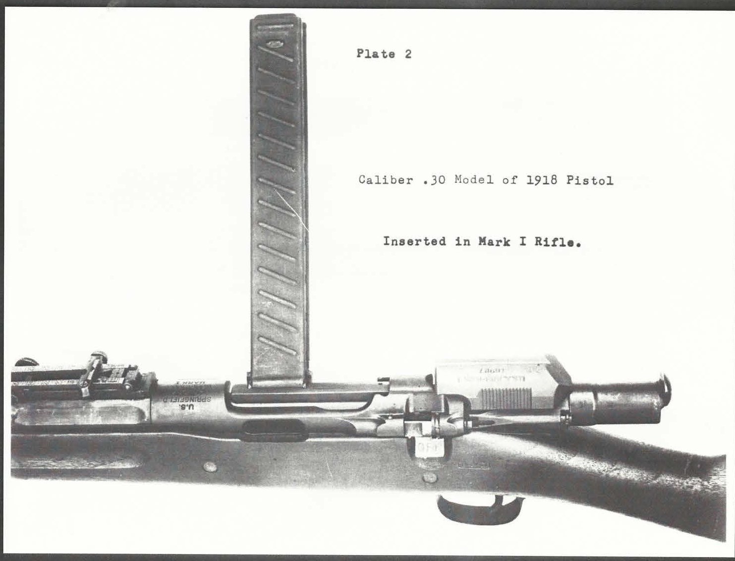
4. Insert the device. “While pulling rifle trigger with right hand … insert barrel of pistol in bolt hole of receiver, push it forward to the proper position and turn down the rifle cut-off to lock pistol in place.” Then: “Unless cut-off is turned down to lock pistol in place, the slide cannot be retracted to load same.”
All quotations: the manual, chapters II and III.1
6.3 End adjustment: the device’s headspace
The device’s barrel sits in the rifle’s chamber; its frame is held by the cut-off. The distance between the two is set by screwing the barrel into or out of the frame, and the manual makes it an armourer’s check at issue: “When locked to rifle, cut-off turned down, the pistol should be snug, with very little or no end play. When issued to the soldier, and occasionally thereafter, the end adjustment should be made or checked, using a pair of special wrenches for the purpose of adjustment.”1
The procedure, in the manual’s order:
- Loosen the barrel nut at the front of the frame with the spanner end of one wrench, while the other wrench is “placed in holding position near front end of ribs on frame”. The barrel nut has an “ordinary right hand thread”.
- Screw the barrel in or out as needed, “and then lightly tighten up barrel nut”.
- Insert the device into the rifle and turn down the cut-off.
- Test: “Firmly grasping rear end of frame of the pistol and alternately pushing and pulling in and out of the rifle receiver will show whether or not end play exists.”
- “Repeat this until a snug end adjustment is obtained and then FIRMLY tighten the barrel nut to secure the barrel. After tightening the barrel nut FIRMLY, try the pistol again in the rifle to prove the correctness of the end adjustment.”
The test of correctness: “the cut-off in the down position holds the frame of the pistol from moving rearward and the shoulder on the barrel of the pistol is snug against the ramp at the rear end of the rifle barrel.”1
The wrenches came “with every ten pistols”, and 800 of them were stored at Panama Arsenal with 4,000 devices in 1920, the same ratio.12 They appear in many surviving outfits (Volume 2). The manual gives no figure for acceptable end play beyond “very little or no”, and no torque for the barrel nut. Faulty end adjustment is listed as a cause of failure to fire (below), and the manual’s emergency removal procedure exists partly because of it.
The fit is between this device and this rifle’s chamber. A device adjusted to one Mark I is not adjusted to another, which is why the Army recommended keeping them paired.2
6.4 Loading, firing and unloading
Attach a magazine. Hold the rifle with the left hand on the fore-end, muzzle down. With the right hand, holding the magazine near its feeding end with the numbered rear side to the rear, “slanting the upper end of magazine well back over the wrist, engage the two rear locking shoulders on lower end of magazine under both magazine latches of the pistol. Holding this position of the magazine, pull it straight toward the rear to draw back the magazine latches. Then swing upper end of magazine forward until the two front locking shoulders are in position to go under the two fixed claws on the frame and push the magazine forward”. If the first cartridge has slid forward and stops the front shoulders engaging, take the magazine off and push the round back. “Before attaching magazine, see that first cartridge is back in magazine as far as it will go, also that the slide is fully forward.”
Load. “Grasp the slide handle with the two first fingers of the right hand, draw the slide smartly to the rear, and let it fly forward.” If the slide does not go fully home, retract it “a short distance only, and then urged completely forward by hand.”
Fire. “Pulling the trigger will fire one shot. To fire again, release trigger and pull again … REMEMBER — Rifle is always loaded and cocked after firing until magazine is emptied. Always work slide and pull trigger after removing magazine.”
Detach the magazine. “Grasp magazine down as low as possible with right hand and pull straight to the rear at the bottom while holding top of magazine forward until front locking shoulders on magazine are disengaged from fixed claws on frame. Then swing the top of magazine back and lift magazine out.”
All: the manual, chapter V.1
6.5 Taking the device out
Normally. “First — Detach magazine from pistol, empty the chamber by retracting the slide to eject the cartridge and then snap the firing pin by pulling the trigger. The pistol cannot be normally removed from the rifle when the firing pin is cocked.” Hold the trigger back; turn the cut-off to the middle; grasp the slide handle with the fingers of the left hand, thumb behind the frame cap; “Pull slide back in frame a short distance by squeezing the left hand and while maintaining this grasp withdraw pistol rearward out of receiver.” Put the device in its scabbard, put the bolt back, and set the cut-off “ON” or “OFF”.
When the firing pin will not snap. The manual allows that “the firing pin cannot be snapped by pulling the trigger, due to derangement of the firing mechanism or to faulty adjustment of the barrel.” Then: “Unscrew the frame cap and remove with piston assembly and three springs. While holding the slide securely forward in the frame, elevate the muzzle of the rifle to the vertical position and strike the butt plate with the right hand to shake out the firing pin. When firing pin is out, hold the rifle as above for the normal removal of the pistol, unlock the cut-off and withdraw the pistol while holding the trigger back.”
Both: the manual, chapter III.1 The chamber must be empty before either.
6.6 Field strip (to dismount)
The manual’s “To Dismount”, with the device out of the rifle, empty and uncocked:1
- Hold the frame in the left hand, frame cap to the right.
- With the thumb, push the frame cap lock forward and turn its head to engage the holding slot on the frame.
- “Unscrew frame cap while holding it to prevent sudden release of springs; remove frame cap with piston assembly, buffer spring, slide spring and firing pin spring.” The springs pull off the piston assembly.
- Pull the slide back out of the frame and drop the firing pin out of the slide.
- Push in on the rear of the disconnector, grasp its front, move it rearward to unhook it from its pin, and remove it.
- With the tail of the sear lever turned outward nearly at right angles to the frame, pull the sear lever assembly, with the sear, off the sear hinge pin and out of the frame.
The Infantry School timed a trained soldier at 2 minutes 30 seconds to dismount and 5 minutes to assemble.3
6.7 Detail strip: extractor, frame cap lock, safety lever and latches
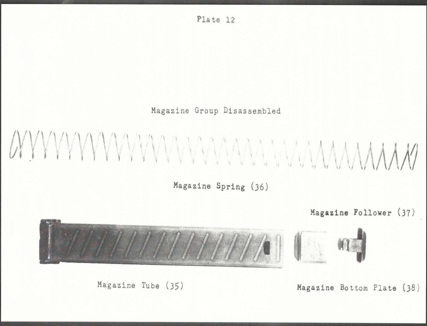
Extractor. “Engage the small hook at front end of disconnector under the claw of extractor, spring the extractor outward until extractor stud is free, and while holding in this position, pry the extractor forward and out of the slide.” The disconnector is the tool.
Frame cap lock and safety lever. Turn the frame cap lock’s head clear of the holding notch and remove the lock, its spring and the safety lever plunger. “Swing front end of safety lever outward, at right angle to frame, and pull out safety lever.”
Magazine latches (“Seldom Necessary”). Separate the spring from the frame cap lock and use the lock’s stem as a tool. Insert the frame part way into the rifle receiver and, with the disconnector held against the rear of the receiver to block the front of the latch, push the frame forward, compressing the latch spring, until the small hole in the latch plunger lines up with the hole in the rear of the latch. Pin them with the pointed end of the frame cap lock. Withdraw the frame part way and lift the latch out. “Hold rear end of magazine latch firmly against a block of wood to prevent spring and plunger from ‘shooting’ away, and pull out frame cap lock. NOTE: This spring is very strong and should not be released carelessly as it may become lost or might strike the operator.” The other latch comes out the same way.
All: the manual, chapter II.1
6.8 Assembly
The manual’s “To Assemble”, which is not simply the reverse:1
- Magazine latches. Put the frame fully into the receiver; stand the rifle muzzle down, butt up, between the knees. Put spring and plunger into the latch; straddle the notch at the front of the plunger over the outer wall of the frame cap lock hole in the frame; “Apply considerable force to push the magazine latch toward the muzzle in order to compress the spring.” Pin it with the frame cap lock, take the frame out, drop the latch into its seat, hold it rearward and inward “strongly”, pull the pin and let it move slowly forward.
- Extractor. Start its rear end into its seat in the slide and push it rearward until the stud meets the slide face; spring the front outward until the stud clears; push it back until flush. “The extractor should now snap inward to proper place. Test extractor to see that it has proper spring tension inward.”
- Safety lever and frame cap lock. Trunnion end of the safety lever into its seat at right angles, then turned forward into its slot; the safety lever plunger, frame cap lock spring and frame cap lock into the hole near the rear of the frame on the left side; push the lock forward and turn it into the holding slot.
- Slide. Frame horizontal, bottom up, rear to the right; insert the slide until its rear is flush with the rear of the frame.
- Sear lever and sear. Check the sear lever pin is flush with the sides of the sear. Hold the assembly so that “the bevel cut at bottom front end of sear lever is in alignment with front face of sear”; with the sear lever’s tail at right angles, put the sear’s semicircular recess over the sear hinge pin; turn the tail rearward into the slot in the bottom lug of the frame.
- Disconnector. Pull the slide fully back; insert the rear of the disconnector into its slot and hook it over its pin; turn its front forward and inward to hold the sear lever’s tail.
- Firing pin. Holding the disconnector down, insert the firing pin with its lug in the keyway in the slide; move the slide forward until flush. “This secures the disconnector in place.”
- Springs, piston and frame cap. Buffer spring, slide spring and firing pin spring on the piston assembly; buffer spring and piston into the frame cap; front of the firing pin spring into its seat in the firing pin; push the frame cap on, compressing the springs, and screw it home; turn the frame cap lock to snap into the notch on the cap.
- “The pistol will now be in a cocked position and the firing pin must be uncocked or snapped before the bolt can be inserted into the rifle receiver” (above).
6.9 The magazine
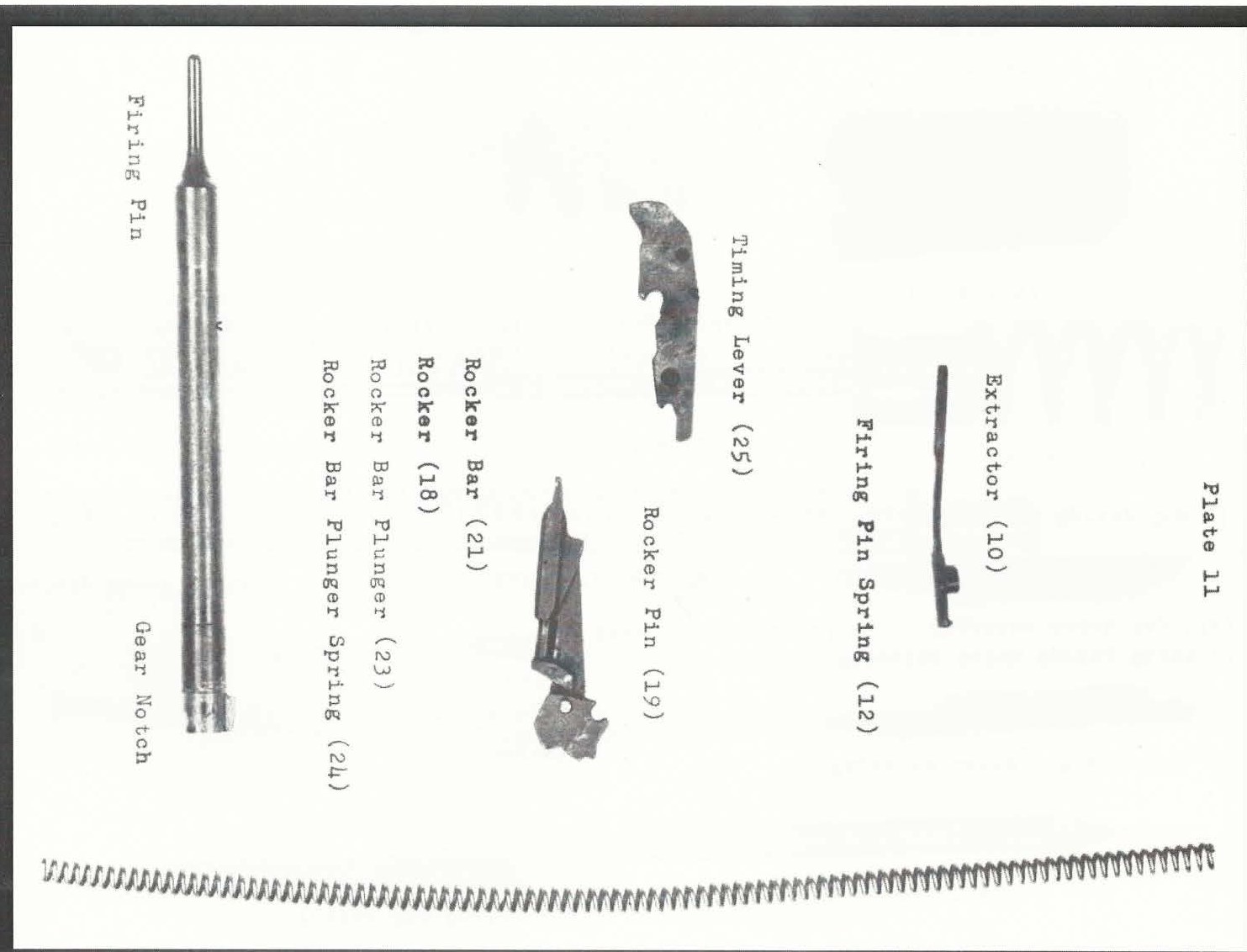
To strip: “Simultaneously press in on the exposed ends of both legs of the magazine bottom plate, at the same time checking the magazine bottom plate with the hand to prevent it flying off.” Remove the plate in line with the tube, holding the spring so it does not buckle, then the spring and follower.
To assemble: drop the follower into the tube and insert the spring; place the bottom plate over the free end of the spring, its legs straddling the spring; support the spring against buckling and push the plate into the open end, squeezing the legs in, until “both of its legs snap outward into their proper locked position in the holes at the upper end of the magazine tube.”
Both: the manual, chapter VI.1 The manual’s words are that the bottom plate goes in at the “open or upper end” and locks in holes “at the upper end of the magazine tube”. The manual is reproduced as written; the scan does not make clear which end of the tube it means by “upper”.
6.10 Cleaning and preservation
The manual: “The pistol should be cleaned and oiled as soon as possible after firing. To do this thoroughly the frame cap should be unscrewed and the slide and firing pin, disconnector and sear lever assembly should be removed. The frame and slide may now be wiped clean inside and out and the other parts cleaned as well. Pay particular attention to cleaning the dirt from around the fixed claws at the front end of the frame and from around the rear end of the barrel. Washing with gasoline will aid the removal of caked powder residue. The barrel should be cleaned and oiled with the same care and attention given to the rifle barrel. Coat all parts lightly but thoroughly with light oil and assemble.”1
Lubrication: “It is not necessary to remove the magazine latches for cleaning except at infrequent intervals. Ordinarily the magazine latches should be oiled with a squirt can without removal from frame.” The magazine’s interior collects fouling at its mouth: “Gasoline or kerosene will aid in removing the encrusted powder residue from the interior of the magazine near the feeding end.”1
Storage: “If the pistol is not to be used for a considerable time, it should be completely protected with a coat of cosmic grease in the same manner as it is prepared for packing and storing.”1 Cosmic grease is the Army’s cosmoline.
Gasoline is the 1918 solvent. A modern owner would use a gun solvent, for the obvious reason, and nothing in the manual depends on gasoline specifically. Whether the original Remington and Frankford ammunition used corrosive primers is not stated in any source found; a device fired with original ammunition should be cleaned as if it did, as the M1 Garand dive advises for the service ammunition of the same era.
6.11 What wears
The manual gives no inspection schedule and no replacement intervals. The sources found give three indications of what wears:
- The insert barrel. After 7,500 rounds in the Infantry School’s endurance test, the chamber-insert barrels were “badly eroded”.3
- Springs. The manual lists a weak firing pin spring, weak buffer spring and weak slide spring as causes of stoppages (below). One device sold in 2022 “does not properly cock”.4
- The extractor. “Broken or weak extractor” appears twice in the stoppage table.
The same test found function “perfect” to about 5,000 rounds, after which powder fouling caused malfunctions that oiling cured.3 That matches the manual’s emphasis on the slide being “properly oiled”.
6.12 Stoppages and malfunctions: the manual’s table
The manual classifies stoppages by where the slide stopped.1
First position: slide all the way forward.
Table 1 — First position: slide all the way forward.
| Stoppage | Causes (the manual’s list) |
|---|---|
| Misfire | Defective ammunition, “if primer is properly indented” |
| Failure to fire | 1. Broken or gummed firing pin. 2. Weak or gummed firing pin spring. 3. Obstruction in firing pin hole in slide. 4. Faulty end adjustment of barrel. 5. Imperfect rocker bar assembly, timing lever or rifle sear parts |
| Failure to feed | 1. Weak cartridge did not complete reloading of chamber. 2. Magazine improperly charged. 3. Action gummed or dry |
Immediate action: “Retract slide by hand and let it fly forward. If malfunctions occur in succession see that the slide is properly oiled. If this does not correct the trouble, remove pistol from rifle, dismount mechanism and put in order.”
Second position: slide partly open.
Table 2 — Second position: slide partly open.
| Stoppage | Causes (the manual’s list) |
|---|---|
| Failure to eject | 1. Broken or weak extractor. 2. Weak buffer spring. 3. Action gummed or dry |
| Jammed cartridge | 1. Imperfect or battered cartridge. 2. Defective or bent magazine mouth. 3. Cartridge charged backwards in magazine. 4. Weak slide spring or action gummed. 5. Failure to extract fired shell from chamber (weak or broken extractor). 6. Burrs on slide or slideway in frame |
Immediate action: “Grasp slide handle with left hand and pull slightly to rear to relieve tension on jammed cartridge. Holding slide in this position, remove magazine with right hand. Now with right hand hold slide open while pushing obstructing cartridge or shell toward left and out through ejection port with tips of fingers of left hand, palm of left hand supporting rifle under receiver. See that all is clear, then remove fingers from slideway and let slide fly forward. Arrange first cartridge in magazine, rejecting if deformed. Attach magazine, pull slide back to reload chamber and resume firing.”
And for both: “If stress of battle or firing conditions do not allow sufficient time to dismount the pistol and put in order, the soldier may restore the hand bolt to his rifle and proceed with magazine fire using the regular (Model ‘06) cartridges.”1
Two causes in the first table are in the rifle, not the device: “rifle sear parts”, meaning the Mark I’s altered sear and trigger lever, and “faulty end adjustment”, which is the fit between device and chamber. A device that will not fire in one Mark I may be sound and the rifle at fault.
6.13 Repair and parts
What an owner can do at the bench, on the manual’s own terms: clean, oil, dismount and assemble; check the extractor’s tension; check and correct end play with the wrenches; replace a part with a known-good original. Those are the soldier’s and armourer’s operations the manual describes.
What needs a specialist: any work on a spring, the extractor or the firing pin beyond replacement, because no new parts exist. No supplier of reproduction device parts, springs or magazines was found in a search on 19 October 2026. A broken part must be made, which on a rare original means a gunsmith with collector experience and a decision about originality that belongs to the owner. Refinishing affects value: Rock Island Auction described a refinished device with “scattered moderate pitting” as “a solid representative example”, a lower grade than an unrefinished one.4
Parts for the rifle. A standard M1903 sear, trigger and cut-off are available on the surplus market; the Pedersen sear, trigger lever and grooved cut-off are original parts found only on original-configuration rifles or loose in collections. No reproduction was found.
6.14 What could not be established
- Acceptable end play in figures, or the barrel-nut torque.
- Any inspection schedule or replacement interval. The manual gives none.
- Whether the original ammunition is corrosive.
- Which end of the magazine the manual means by “upper” in its stripping instructions.
- Any current source of parts.
References
Footnotes
-
Notes on Caliber .30 Model of 1918 Pistol, CONFIDENTIAL, Small Arms Division, Ord. Dept., Machine Gun Section; S. G. Green, Captain. Undated. Chapters I–VI and VIII; plates II, VI, XI, XII. Internet Archive, https://archive.org/details/pedersen-device-manual (accessed 2026-10-19). ↩ ↩2 ↩3 ↩4 ↩5 ↩6 ↩7 ↩8 ↩9 ↩10 ↩11 ↩12 ↩13 ↩14 ↩15 ↩16
-
Jonathon Krisko, “The Pedersen Device: Its Design, Production & Post-War Issuance”, American Rifleman, 12 September 2024, https://www.americanrifleman.org/content/the-pedersen-device-its-design-production-post-war-issuance/ (accessed 2026-10-19). ↩ ↩2 ↩3
-
Jonathon Krisko, “The Post-War Pedersen Device: Infantry Testing & Ultimate Fate”, American Rifleman, 14 September 2024, https://www.americanrifleman.org/content/the-post-war-pedersen-device-infantry-testing-ultimate-fate/ (accessed 2026-10-19). ↩ ↩2 ↩3
-
Rock Island Auction Company, 27 August 2022, lot 1458, https://www.rockislandauction.com/detail/86/1458/us-springfield-1903-rifle-with-pedersen-device-and-accessories (accessed 2026-10-19). ↩ ↩2
Comments (0)