Pedersen Device · Volume 4
How It Works: A Blowback Pistol Inside a Bolt Rifle
The barrel that fills the rifle's chamber, the frame the cut-off locks, a slide with a weight on its back, a piston and buffer behind it, a firing pin that doubles as the ejector, the train from the rifle's trigger to the device's sear, and how the 1917 patent's open bolt became the production gun's cocked striker
4.1 What kind of action it is
The device is a straight blowback self-loader. Nothing locks the breech. The Army manual’s account of the cycle begins: “The recoil of the cartridge case, applied to the face of the slide, drives the slide rearward, compressing the slide spring and the firing pin spring.”1 Hatcher, who examined it in 1917, called it “very much the same thing as a straight ‘blowback’ type automatic pistol without any stock, the dimensions of what would otherwise be a pistol being changed sufficiently to adapt it to fit in the rifle in place of the bolt”.2
What makes a straight blowback safe is mass and spring: the breechblock must be heavy enough, and held forward hard enough, that the case does not leave the chamber while the pressure is still high. Pedersen added mass in an unusual place. Hatcher: “Looking at the picture of the device, it will be seen that there is a little lump, or weight, on the top. Every time the gun is fired this lump, which is part of the breechblock, slides to the rear and then jumps forward again, something like a mouse running backward and forward on top of the receiver. It is the inertia of this weight which enables a powerful cartridge to be used”.2 The Springfield patent describes the same part: the bolt has “an arm or projection” through a slot in the frame that “carries a weight which also serves as a handle whereby the bolt may be retracted by hand”.3 The manual calls it the slide handle.
Behind the slide the device has a second stage, a piston and buffer, which the cycle below describes. No source found gives the slide’s weight, the spring rates or the chamber pressure, so the margin of safety of the blowback cannot be calculated from published data.
4.2 The parts, by the manual’s numbers
The manual numbers 38 parts. Grouped by function:
Table 1 — The manual numbers 38 parts. Grouped by function
| Group | Parts (manual numbers) |
|---|---|
| Frame | 2 frame; 3 frame cap; 4 frame cap lock; 5 frame cap lock spring; 8 safety lever; 9 safety lever plunger |
| Barrel | 6 barrel; 7 barrel nut |
| Slide group | 1 slide; 10 extractor; 11 firing pin; 12 firing pin spring; 13 firing pin spring guide |
| Recoil system | 14 piston (piston assembly); 15 slide spring guide; 16 slide spring; 17 slide spring bushing; 34 buffer spring |
| Firing mechanism | 18 sear; 19, 22 sear lever; 20 sear hinge pin and 21 sear stop pin (permanently assembled to the frame); 23 sear lever plunger and 24 its spring (with the rocker and rocker pin, “the rocker bar assembly”); 25 disconnector; 26 disconnector hinge pin (permanent); 27 disconnector stop pin |
| Magazine catches | 28 magazine latch, right; 29 magazine latch, top; 30, 31 latch plungers; 32, 33 latch springs (“interchangeable”) |
| Magazine | 35 tube; 36 spring; 37 follower; 38 bottom plate |
Source: the manual’s nomenclature, pages 2–3.1
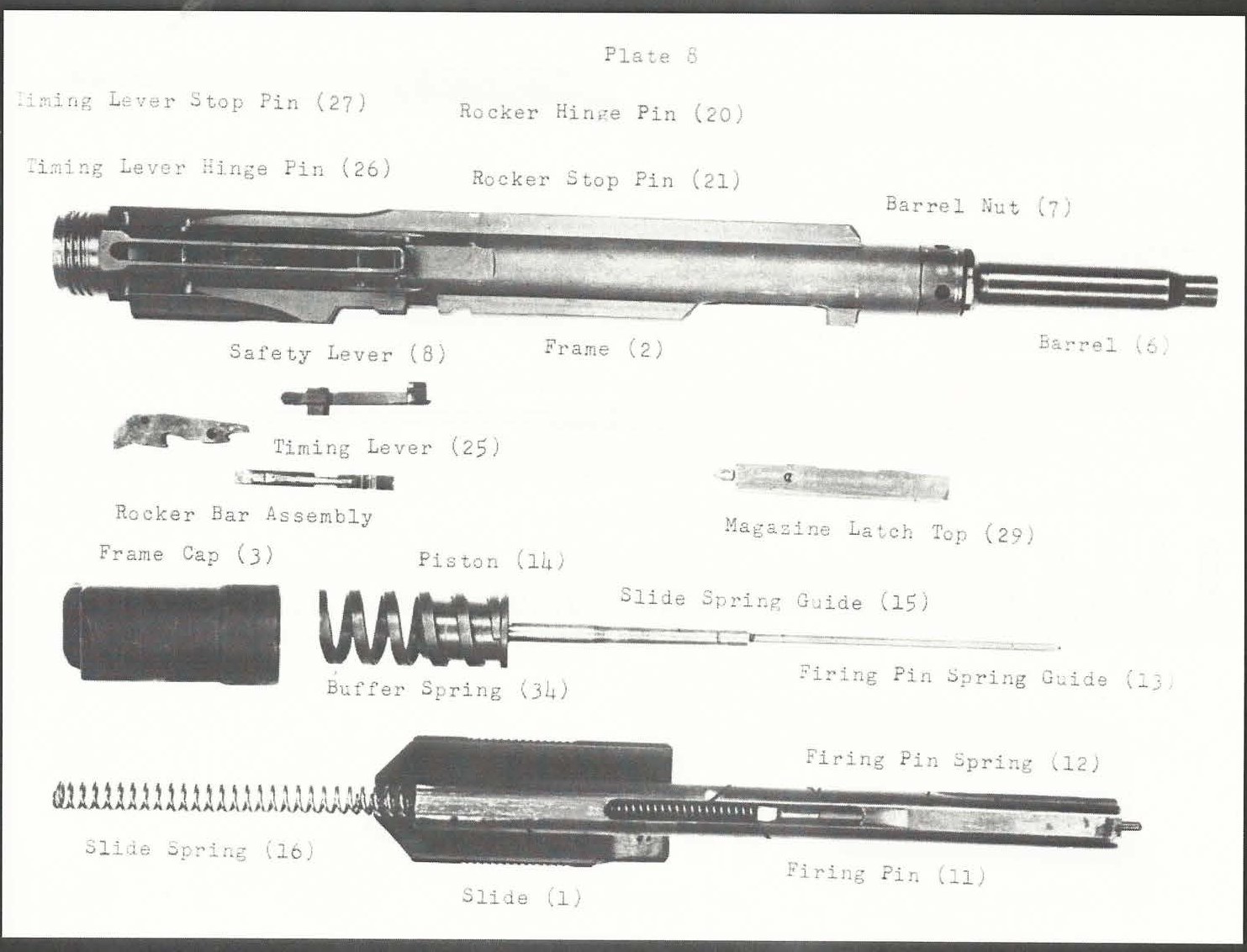
The manual uses two vocabularies for the firing group. The text speaks of the sear, sear lever and disconnector. The photographic plates label the same parts rocker (18), rocker pin (19), rocker hinge pin (20), rocker stop pin (21), rocker bar (22), timing lever (25), timing lever hinge pin (26) and timing lever stop pin (27).1 The manual does not explain why it uses two sets of names. This dive uses the text’s.
4.3 How the device sits in the rifle
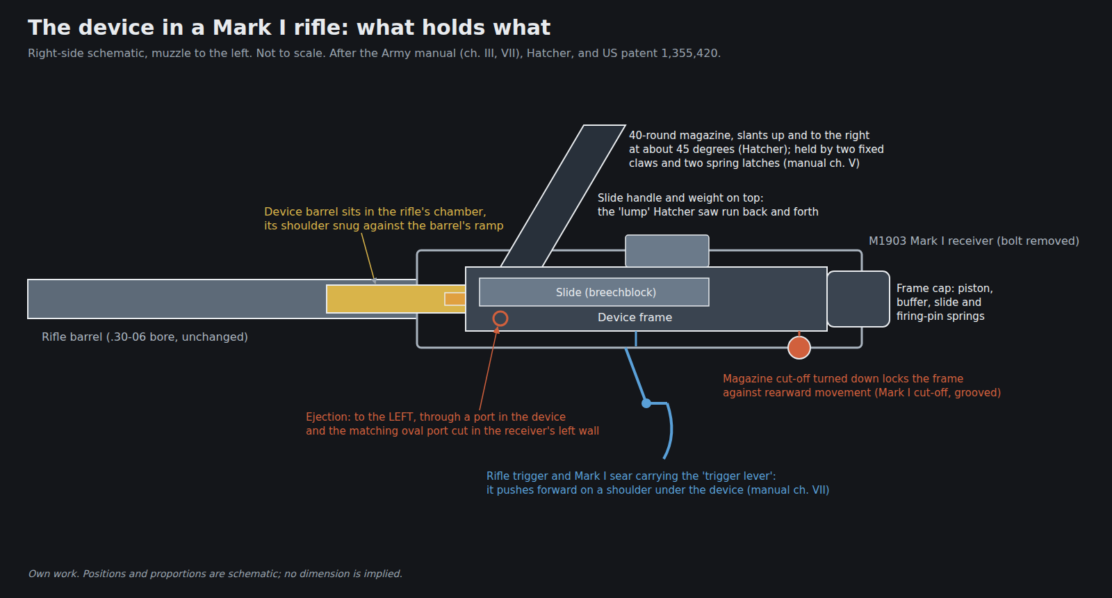
The device replaces the bolt and nothing else. Its frame fills the bolt way of the receiver. Its barrel reaches forward into the rifle’s chamber. It is held in the receiver by the rifle’s own magazine cut-off, altered on the Mark I. The manual: “insert barrel of pistol in bolt hole of receiver, push it forward to the proper position and turn down the rifle cut-off to lock pistol in place.” And: “Unless cut-off is turned down to lock pistol in place, the slide cannot be retracted to load same.”1 Hatcher says the Mark I’s cut-off had “two grooves” for this.2 When it is right, “the cut-off in the down position holds the frame of the pistol from moving rearward and the shoulder on the barrel of the pistol is snug against the ramp at the rear end of the rifle barrel.”1
So the thrust of firing goes from the case head into the slide, through the springs and piston into the frame cap and frame, and from the frame into the cut-off and so into the receiver. The barrel is held between the frame’s front end and the rifle barrel’s chamber shoulder. That is why the fit between those two has to be adjusted (Volume 6): any end play lets the whole device hammer back and forth against the cut-off.
The device can only go in uncocked. The manual: the pistol “can not be inserted, if cocked, into the rifle”, and the soldier pulls the rifle’s trigger while inserting it.1 The manual does not say why the trigger must be held back; the likeliest reading is that it keeps the Mark I’s trigger lever out of the way of the device’s frame, but that is an inference.
4.4 The barrel inside the barrel
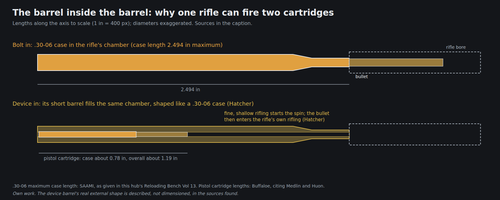
Hatcher: “The barrel of the pistol was just the same size, shape, and length as the regular Springfield rifle cartridge (without the bullet). This little barrel is rifled with fine rifling larger in diameter than the rifling in the Springfield barrel. Thus this short barrel does not have to have the rifling match that in the regular barrel. The short barrel starts the bullet spinning, but the fine rifling does not take in very deeply, so that when the bullet strikes the regular barrel it is not sized down too small for the regular rifling to take hold.”2 The patent says the same in its own language: the short barrel “will closely fill the usual cartridge chamber of the barrel of the primary arm” and serves “as a combined adapter and barrel-extension for the primary arm while serving as the barrel of the secondary arm”.4
Culver says the chamber insert was “rifled with ten shallow lands and grooves”.5 No other source found gives the number. The manual gives “Caliber bore – 0.305 inches”; it does not say whether that is the device’s bore or the bullet.1
This arrangement explains a finding of the Infantry School’s endurance test: after 7,500 rounds the insert barrels were “badly eroded” (Volume 3).6 The short barrel took the full heat and pressure of every shot at its throat, and it was the cheapest part to replace. It also explains why the rifle’s chamber is not harmed by the device: the cartridge never touches it.
4.5 The magazine and its catches
The magazine is a single long tube holding 40 rounds. The manual’s loading instructions show that the cartridges lie across the tube’s width, bases to the rear: “Be sure to charge magazine with the base of all cartridges toward the rear side of magazine. The rear side of magazine carries indicator slots and numerals to indicate the number of cartridges in the magazine.”1 Plate 1 calls this the “register index”.
It attaches to the right-hand top of the device. Two fixed claws on the front of the frame take the magazine’s two front locking shoulders; two spring-loaded magazine latches, “right” and “top”, take its two rear shoulders. To attach it, the soldier hooks the rear shoulders under both latches, pulls the magazine to the rear to draw the latches back, swings its upper end forward so the front shoulders go under the claws, and pushes it forward.1 Hatcher: the magazine, “when placed in position slanted upward, and to the right at an angle of about 45 degrees.”2 Cartridges feed downward from it into the device as the slide passes.
The latch springs are strong. Removing a latch is “Seldom Necessary”, and the manual warns that “This spring is very strong and should not be released carelessly as it may become lost or might strike the operator.”1
4.6 The firing train
The device has its own sear. The rifle has its own trigger. Between them is the Mark I’s key change: a trigger lever pivoted in the rifle’s altered sear. Hatcher: “The actual release of the firing mechanism is accomplished by pushing forward on a projection on the bottom of the device. A little pivoted lever in the sear of the rifle fits in the notch in the bottom of the device, and gives the necessary forward impulse when the trigger of the rifle is pulled.”2
The manual traces it in order. “Pulling the trigger moves the top end of the trigger lever forward, (the trigger lever being mounted in the rifle sear). The trigger lever engaging the shoulder on the sear lever pushes the sear lever forward endwise. The front end of the sear lever being pivoted to the sear, swings the cock notch on the sear downward and out of engagement with the notch on the firing pin. This releases the firing pin and allows it to be driven forward by the firing pin spring to fire the cartridge in the chamber.”1
The disconnector sits between the slide and the sear lever. As the slide starts back, “the back end of the slide rides over the rear end of the disconnector to depress the disconnector. This forces the front end of the disconnector upward and carries with it the tail of the sear lever, thus disconnecting the shoulder on the sear lever from the trigger lever mounted in the rifle sear. Operative connection between the shoulder on the sear lever and the trigger lever of the rifle is not again restored until the slide is in its complete forward position.” The manual states the result: “The disconnection of the sear lever from the trigger lever of the rifle prevents more than one shot being fired at each pull of the trigger and also prevents firing the pistol unless the slide is in its forward or home position.”1 When the slide returns home, the sear lever’s spring swings the disconnector back, and the connection is re-made “when the trigger is released, so that the trigger lever may move back of the shoulder on the sear lever.”1
Two consequences follow. The device is semi-automatic by design: one pull, one shot. And the trigger must be released fully between shots for the trigger lever to drop behind the shoulder again. The manual’s instruction to the soldier is written to match: “Pulling the trigger will fire one shot. To fire again, release trigger and pull again, one trigger pull for each shot until magazine is emptied.”1
4.7 The cycle, step by step
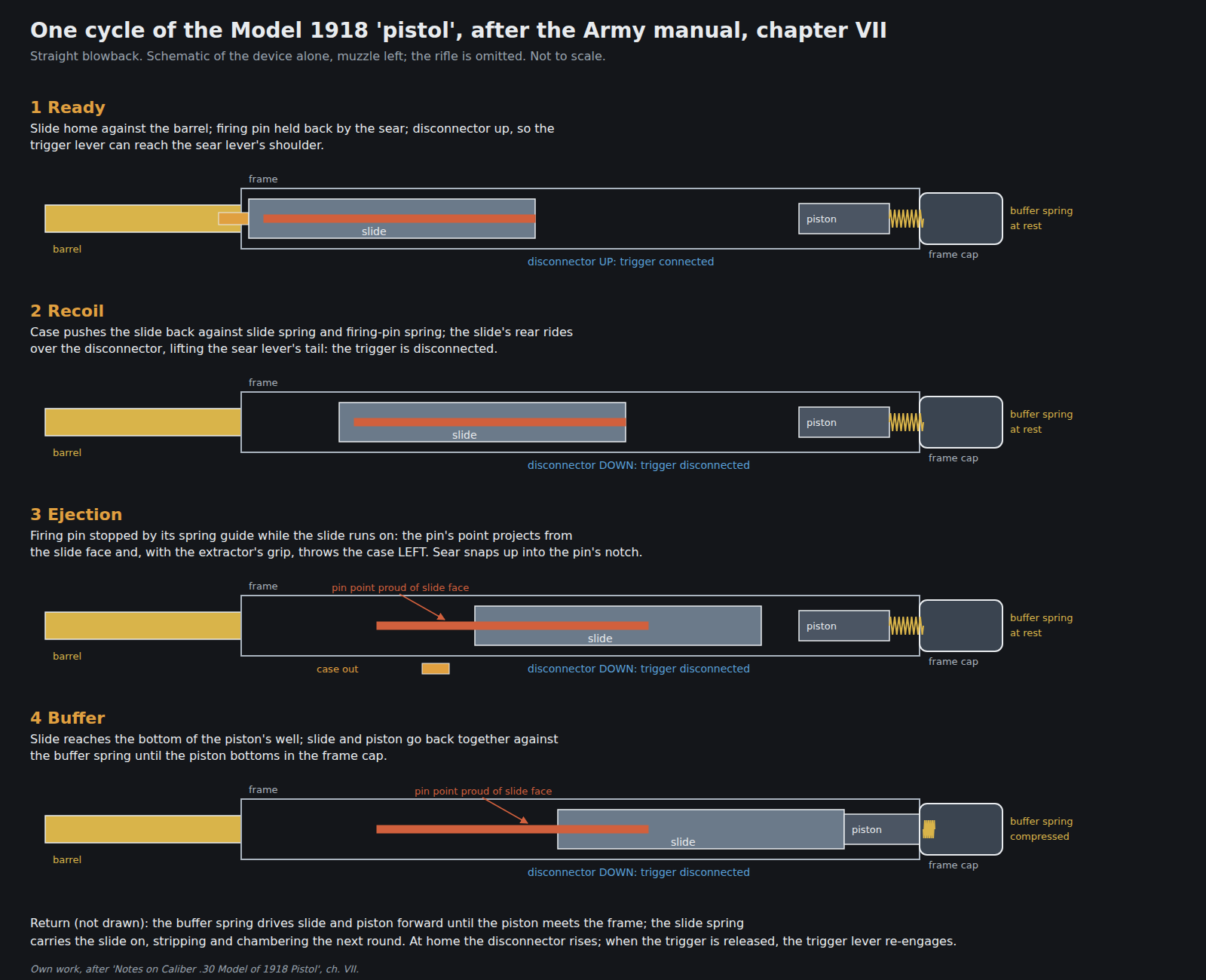
The manual’s chapter VII, “Detailed Action”, in order:1
- Recoil. The case drives the slide back against the slide spring and the firing pin spring. The extractor holds the case on the slide face.
- Disconnection. The slide’s rear rides over the disconnector, which lifts the sear lever’s tail off the trigger lever.
- The firing pin stops. “Just before the front end of the slide has moved back far enough to uncover the cartridge in the magazine, the rearward movement of the firing pin is arrested by the front end of the firing pin spring guide coming in contact with the end of the long hole in the firing pin.”
- Ejection. “The slide continuing back over the firing pin, causes the point of the firing pin to project through the front end of the slide, and this in connection with the grasp of the extractor ejects the shell toward the left and through the ejection port.”
- Cocking. At about the same moment, “the cock notch on the firing pin has reached a position back of the similar cock notch on the sear, and the sear snaps upward into the cocked position.”
- First stop. The slide runs on “until its rear end strikes the bottom of the well hole in the piston”. Until then the piston’s front end rests against the rear of the frame.
- Buffer. “The remaining rearward energy of the slide continues to move back the slide and piston, compressing the buffer spring until the rear end of the piston bottoms in the frame cap.”
- Return. The buffer spring pushes slide and piston forward until the piston meets the frame; the slide spring carries the slide on, “the face of the slide driving the cartridge from the magazine into the chamber”, and the slide stops against the rear of the barrel. The firing pin stays behind, held by the sear.
- Reconnection. At home, the disconnector rises and the trigger can be reset.
The two-stage stop is the distinctive part. The slide first compresses the light springs, then picks up the piston and decelerates against the heavy buffer spring. The buffer spring then gives the slide a strong start forward. A device whose buffer spring is weak will fail to eject: the manual lists “Weak buffer spring” among the causes of failure to eject (Volume 6).1
The manual’s rate for the whole system, including magazine changes, is “about 200 per minute” of unaimed semi-automatic fire. Krisko reports “about 100 aimed shots per minute” in testing.17
4.8 A firing pin that ejects
Most self-loaders have a fixed ejector. The device has none. Its firing pin is stopped early by its spring guide while the slide continues back, so the pin’s point stands proud of the slide face and knocks the case off the extractor and out to the left (step 4 above). The patent describes the same arrangement: “the retraction of the firing pin in the bolt is stopped by the end of the tube before the bolt has been fully retracted.”4
That has a practical consequence the manual turns into an inspection. Because the firing pin’s point shows at the front of the slide whenever the pin is forward and the slide is drawn back a little, the soldier checks that the device is uncocked by “drawing the slide back about one-half inch so as to expose the front end of slide through the ejection port. If point of firing pin is not visible through front end of slide in this position, the firing pin must be snapped”.1
The rifle’s own ejector plays no part. The Springfield patent notes that the rifle’s ejector projects into a channel in the receiver and that the device’s frame “has means whereby the removal of said ejector” is unnecessary.3
4.9 The safety lever
The nomenclature lists a safety lever (8) and its plunger (9), and the assembly instructions say how they go in: “Insert trunnion end of safety lever into its seat in frame, front end of safety lever at right angle to frame. Turn safety lever forward parallel with frame and into slot.”1 The manual does not say what the lever does or how the soldier uses it. Nothing found here explains its function. It is listed, not described.
4.10 Patent and production: from open bolt to cocked striker
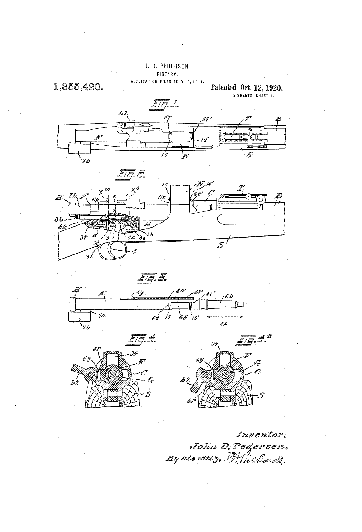
The first patent and the production device fire differently, and the difference is worth stating because the patent drawings are the most widely reproduced drawings of the device.
In US 1,355,417, filed in April 1917, the bolt is held open by the sear: the bolt is retracted “for engaging the retaining face rearwardly of the sear-face”. When released, it runs forward, chambers a round, and “the relatively heavy firing-pin lies loosely and in a fully-retracted position in the bore of the bolt … On the bolt stopping suddenly at the end of its forward stroke, the momentum of the firing pin compresses said pin-retracting spring and thus the point of the pin is driven against the primer and fires the cartridge”.4 That is an open-bolt mechanism with an inertia firing pin.
The production device, as the manual describes it, fires from a closed breech. The slide comes home on a chambered round; the firing pin is held back separately by the sear against its own spring; the trigger releases the firing pin, not the slide (above).1 The patents filed in May and July add the sear-and-lock movement and the Springfield-specific frame,83 and the drawings in the later patents should not be read as the production design without checking against the manual. When the change was made is not recorded in the sources found.
4.11 What could not be established
- Slide mass, spring rates, chamber pressure. Not published in any source found.
- The number of grooves in the insert barrel: ten, on Culver’s word alone.
- What the safety lever does.
- When the open-bolt design of the first patent became the closed-breech production design.
- Whether the manual’s 0.305 in “caliber bore” is the insert’s bore or the bullet’s diameter.
References
Footnotes
-
Notes on Caliber .30 Model of 1918 Pistol, CONFIDENTIAL, Small Arms Division, Ord. Dept., Machine Gun Section; S. G. Green, Captain. Undated. Nomenclature; chapters II, III, IV, V and VII; plates I and VIII. Internet Archive, https://archive.org/details/pedersen-device-manual (accessed 2026-10-19). ↩ ↩2 ↩3 ↩4 ↩5 ↩6 ↩7 ↩8 ↩9 ↩10 ↩11 ↩12 ↩13 ↩14 ↩15 ↩16 ↩17 ↩18 ↩19 ↩20
-
Julian S. Hatcher, Hatcher’s Notebook, chapter XV, “The Pedersen Device”, https://archive.org/details/Hatchers_Notebook (accessed 2026-10-19). ↩ ↩2 ↩3 ↩4 ↩5 ↩6
-
John D. Pedersen, US Patent 1,355,420, “Firearm”, filed 12 July 1917, issued 12 October 1920, specification and sheet 1, https://patents.google.com/patent/US1355420A/en (accessed 2026-10-19). ↩ ↩2 ↩3
-
John D. Pedersen, US Patent 1,355,417, “Firearm”, filed 28 April 1917, issued 12 October 1920, specification, https://patents.google.com/patent/US1355417A/en (accessed 2026-10-19). ↩ ↩2 ↩3
-
Dick Culver, “The Pipsqueak Pistol That Never Was”, Civilian Marksmanship Program, Internet Archive copy of 27 March 2012, https://web.archive.org/web/20120327162014/http://www.odcmp.co/Services/Rifles/pipsqueak_pistol.htm (accessed 2026-10-19). ↩
-
Jonathon Krisko, “The Post-War Pedersen Device: Infantry Testing & Ultimate Fate”, American Rifleman, 14 September 2024, https://www.americanrifleman.org/content/the-post-war-pedersen-device-infantry-testing-ultimate-fate/ (accessed 2026-10-19). ↩
-
Jonathon Krisko, “The Pedersen Device: Its Design, Production & Post-War Issuance”, American Rifleman, 12 September 2024, https://www.americanrifleman.org/content/the-pedersen-device-its-design-production-post-war-issuance/ (accessed 2026-10-19). ↩
-
John D. Pedersen, US Patent 1,355,418, “Mechanical Movement”, filed 29 May 1917, issued 12 October 1920, https://patents.google.com/patent/US1355418A/en (accessed 2026-10-19). ↩
Comments (0)