Hyper-Burst Mechanisms · Volume 8
Modelling the Mechanisms: Non-Firing Kinematic Demonstrators
How to show, on a bench, what the G11's rotating chamber and the AN-94's cable-and-pulley feed actually do, with laser-cut acrylic, printed parts and a hand crank: three demonstrator concepts at teaching-model level, and the boundary that keeps every one of them a model of motion rather than a part of a weapon
8.1 The boundary, first
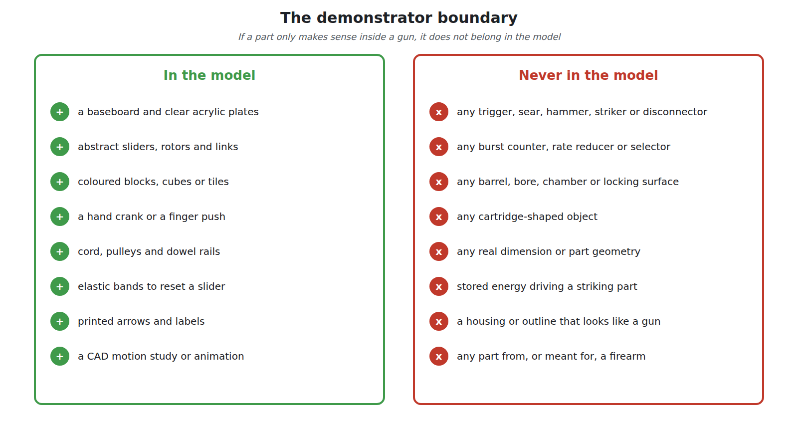
Every weapon in this dive is a machine gun. This volume is about non-firing kinematic demonstrators: teaching models that show how the motion of a mechanism works, and that could not fire, could not be made to fire, and contain nothing that could be used in a weapon. It is explicitly not a build of any firing weapon or any part of one. In particular:
- No dimensions or geometry from the real weapons are given or used. The demonstrators are drawn at mechanism-schematic level, at a scale and in a form chosen so that no part could be mistaken for, or adapted into, a part of a firearm.
- No fire-control parts are modelled at all. No trigger, sear, hammer, striker, disconnector, burst counter or rate reducer appears in any demonstrator in any form, working or dummy. The burst-limiting and rate-changing mechanisms of these weapons are exactly the part of them that matters legally, and they are left out completely.
- Nothing contains a bore, a chamber that accepts a cartridge, or a pressure-bearing part. The “rounds” in the models are coloured blocks of a size and shape no cartridge has.
- Motion is supplied by hand. A crank or a push. No stored-energy mechanism drives anything that strikes anything.
If a proposed part only makes sense inside a gun, it does not belong in the model.
8.2 What a demonstrator is for
Volumes 4 and 5 describe mechanisms whose whole point is the order in which things happen. In a G11 burst, a chamber has to turn a quarter-turn, take a round, turn back and fire three times while the barrel-and-breech assembly is still moving rearward. In an AN-94 burst, a bolt carrier’s rearward travel has to drag a second cartridge forward, through a cable and pulley, into a receiver that is itself moving. Words and still diagrams describe those sequences badly, because they happen in tens of milliseconds and several parts move at once in different directions.
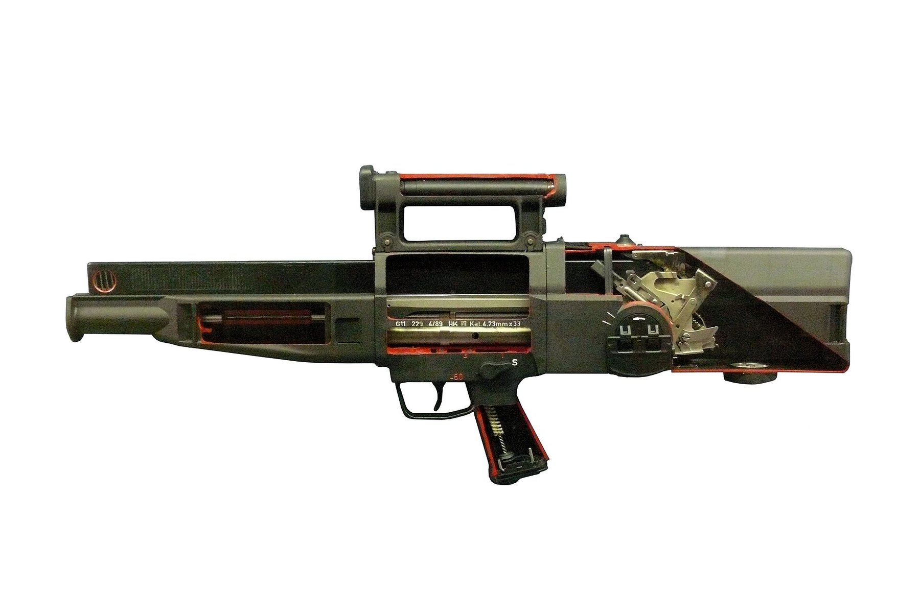
A physical model run slowly by hand makes the sequence visible. That is how armies and makers have taught these mechanisms: the Bundeswehr’s study collection at Koblenz displays a sectioned G11 with windows cut through the housing, and Wikimedia Commons holds an eight-frame kinematic diagram of the G11’s chamber by the German diagram author Grasyl.12 A bench demonstrator goes one step further than a cutaway by letting the viewer drive the motion and watch cause and effect.
The useful demonstrators show relationships: which part drives which, which way each moves, and what has to happen before what. They do not need, and should not have, the real parts’ shapes or proportions.
8.3 Design rules for every demonstrator
These rules apply to all three concepts below. They exist to keep each demonstrator a model of motion and nothing else.
- Change the scale, and do not copy the shape. Build the model on a flat baseboard, abstracted into simple sliders, rotors and links, at a scale and form unrelated to the real weapon. A demonstrator that shows the right relationships is better as a teaching tool when it looks like a mechanism diagram than when it looks like a gun.
- Use materials that could not take pressure or heat. Laser-cut acrylic plates, printed PLA or PETG, wooden dowels, string or cord, elastic bands. No steel pressure parts, no tubes that could serve as a barrel.
- No cartridge-shaped objects. The “rounds” are coloured blocks, cubes or tiles, sized for the model and nothing else. Colour-code them: one colour for the round about to feed, another for the round being “fired”, a third for a “dud” in the dud-clearing demonstration.
- Drive everything by hand. A crank, a knob or a slider pushed by a finger. Elastic bands or light springs may return a slider to rest so the model resets itself, but nothing stores energy to strike anything.
- Make the motion visible. Clear acrylic for covers and guides, coloured parts for the moving members, and printed arrows on the baseboard showing direction of travel.
- Label it. A plate stating what the model shows, that it is a non-firing teaching model, and the sources for the sequence.
8.4 What is never modelled
This list is part of the design, not a footnote.
Table 1 — What is never modelled
| Real weapon feature | In the demonstrator |
|---|---|
| Trigger, sear, hammer, striker, firing pin, disconnector | Omitted. A “shot” is represented by the operator, for example by turning a coloured indicator or lifting a block out by hand |
| Burst counter, rate reducer, fire selector | Omitted entirely, working or dummy |
| Barrel, bore, chamber, locking surfaces, gas port, gas piston | Omitted. The G11 “chamber” in Demonstrator 1 is a slot in a rotor that holds a coloured block, with no relation to a cartridge chamber |
| Real dimensions, travels, angles other than the quarter-turn the sources describe | Not used. Proportions are chosen for visibility on the bench |
| Magazine | A simple holder or tray for coloured blocks |
| Housing that looks like a gun | Not built. The model sits on a baseboard |
8.5 Demonstrator 1: the G11’s quarter-turning chamber
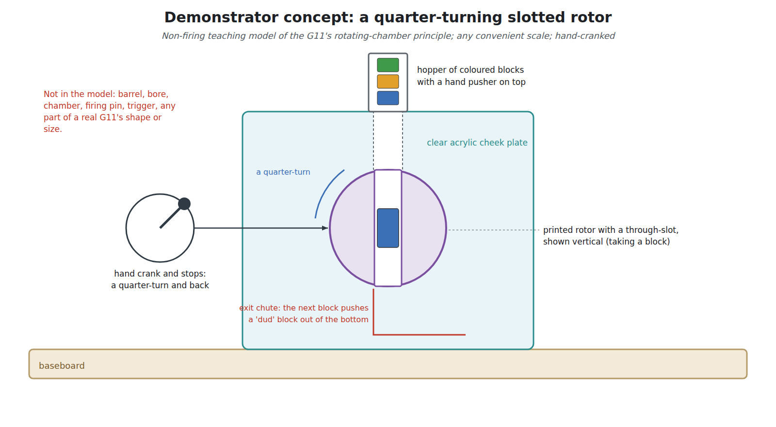
What it shows. The G11’s central idea, from H&K’s 1974 to 1976 patent and its 1989 armourer’s manual: a rotor with a slot bored across it turns a quarter-turn to stand the slot vertical under a magazine, a round drops or is pushed straight down into it, the rotor turns back so the slot lines up with the “barrel” direction, and on the next cycle the next round entering from above pushes anything left in the slot out through the bottom. No case is ever pulled out backwards.34
The parts, abstracted.
- A baseboard with two upright acrylic cheek plates.
- A rotor: a printed cylinder on an axle between the cheek plates, with a through-slot across its diameter sized for the model’s coloured blocks. The slot is open at both ends.
- A block hopper above the rotor: a vertical acrylic channel holding a stack of coloured blocks, standing for the magazine.
- A pusher in the hopper: a printed slide that pushes one block down into the slot when the slot is vertical.
- An exit chute below the rotor, where a block pushed through the slot falls into a tray: this is the dud-clearing path.
- A hand crank that turns the rotor through a quarter-turn and back, with a simple stop at each end. A crank turning a pin in a slotted lever is enough to give a back-and-forth quarter-turn from continuous turning; so is a pair of end stops with the operator turning the rotor directly. The mechanism used is a teaching choice, and nothing about it relates to the real weapon’s cams.
How to run it.
- Rotor horizontal, slot empty: the “ready” position with no round.
- Turn the crank: the rotor turns to vertical; the slot is under the hopper.
- Press the pusher: a block drops into the slot.
- Turn the crank back: the rotor turns horizontal, carrying the block across. This is where the real weapon would fire; in the model the operator lifts the block out by hand, representing a round consumed.
- For the dud demonstration, leave the block in the slot, turn to vertical, and press the pusher: the new block pushes the old one out through the bottom into the tray, the push-through clearing the US Army’s report describes.5
Variant: the floating assembly. Mount the whole rotor-and-hopper assembly on a sliding carriage running on two dowels, with an elastic band pulling it forward. Pushing it back by hand while operating the crank shows that the chamber cycle happens inside a unit that is itself moving, which is the other half of the G11’s idea. Keep the carriage’s travel arbitrary: the point is that it moves, not how far.
8.6 Demonstrator 2: the AN-94’s cable-and-pulley feed
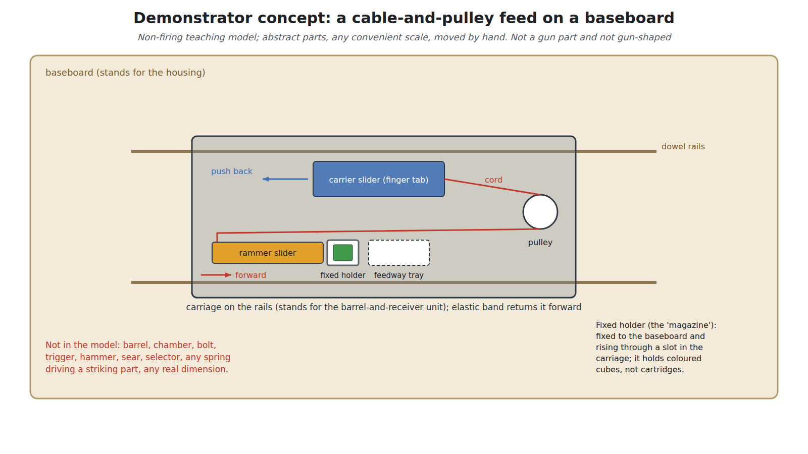
What it shows. The part of the AN-94 that is hardest to picture: a fixed magazine feeding a receiver that is moving, by turning the bolt carrier’s rearward motion into a rammer’s forward motion through a cable over a pulley.6 It also shows why the pulley is part of the feed and not a recoil balancer (Volume 5).
The parts, abstracted.
- A baseboard standing for the housing, with a fixed block holder standing for the magazine, offset to one side.
- A carriage on two dowel rails, standing for the barrel-and-receiver unit, returned forward by an elastic band. It carries a feedway: an open tray that a block can be pushed into.
- On the carriage, a carrier slider in its own guide, returned forward by an elastic band, with a finger tab.
- A pulley fixed to the carriage ahead of the rammer, with a cord tied from the front of the carrier slider, forward over the pulley, and back to the front of a rammer slider that runs in its own guide. A cord can only pull, so the pulley has to be in front: when the carrier slider is pushed back, the cord draws the rammer forward towards the pulley.
- The rammer’s tip lines up with the bottom block in the fixed holder when the carriage is at rest.
How to run it.
- All parts forward: the “ready” state.
- Push the carrier slider rearward with a finger. The cord draws the rammer forward; the rammer pushes the bottom block out of the fixed holder into the feedway on the carriage. This is step 4 of Volume 5’s cycle.
- Let the carrier slider return. In the real rifle, this is where the bolt carrier chambers the round from the feedway; in the model, the block simply sits in the feedway, or the operator moves it on by hand.
- Now repeat with the carriage pushed back part of its travel and held. The rammer still meets the holder because the pulley and the rammer move with the carriage, which shows why the feed has to be arranged this way when the receiver is moving.
What it teaches. That two parts on the same carriage move in opposite directions, linked by the cord; that the pulley is fixed to the moving unit; and that the magazine does not move. It also makes the AS of 1983’s problem obvious: put the block holder on the carriage instead, and the “magazine” swings back and forth with the moving unit, exactly the arrangement the Kalashnikov Museum’s placard says caused stoppages, breakages and injuries.7
8.7 Demonstrator 3: a timing wheel for the burst
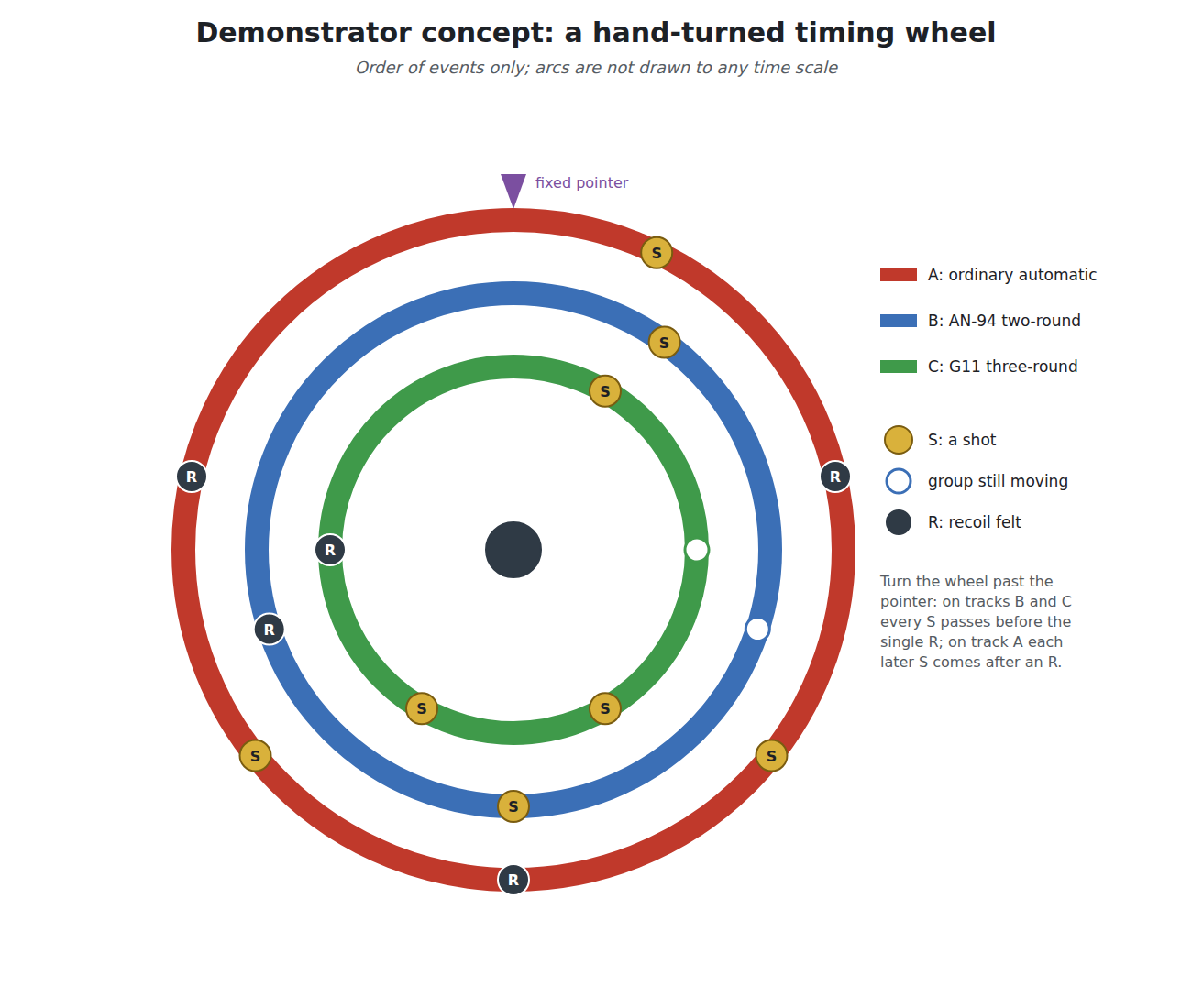
What it shows. The difference between the three firing patterns in Volume 1’s opening figure, as an order of events: an ordinary automatic rifle, the AN-94’s two-round mode and the G11’s three-round burst.
The parts, abstracted. A disc, laser-cut or printed, turned by hand on a centre pin, with three concentric tracks. Around each track, coloured segments mark events in their order: “shot” marks, a band for “moving group travelling back”, and a mark for “group reaches its stop; shooter feels recoil”. A fixed pointer over the disc reads out the sequence as it turns. One full turn of the disc is one burst; the tracks are not drawn to any time scale, only in order.
- Track A, ordinary automatic: shot, stop reached and recoil felt, shot, stop and recoil felt, shot.
- Track B, AN-94 two-round mode: shot, group moving back, shot, then stop and recoil felt once.68
- Track C, G11 three-round burst: shot, group moving back, shot, shot, then stop and recoil felt once.59
Turning the disc past the pointer makes the core idea concrete: in tracks B and C, every “shot” mark passes the pointer before the “recoil felt” mark; in track A, every shot after the first comes after a recoil mark. Nothing on the disc is a part of anything; it is a printed diagram that turns.
8.8 Doing it in CAD instead
The safest demonstrator of all is one that never leaves the computer. A simplified CAD assembly of the abstracted parts above, with a motion study, can run the G11 rotor or the AN-94 feed at any speed, show hidden parts in transparency, and export a video. The same design rules apply: model abstractions, not the weapons; do not import or reconstruct real part geometry; leave out fire control entirely. An animation of the timing wheel’s three tracks, with the moving group’s travel drawn as a bar that fills while shots are marked on it, is often clearer than the physical wheel.
8.9 Which lab tools fit which part
Table 2 — Which lab tools fit which part
| Part | Tool | Why |
|---|---|---|
| Baseboard, cheek plates, guide plates, hopper walls, the timing disc | CO2 laser in clear or coloured acrylic | Flat parts, crisp edges, and clear material that shows the motion |
| Rotor, pulley, sliders, pusher, rammer, carriage | FDM 3D printer in PLA or PETG | Curved and slotted parts that are tedious to cut flat; print in contrasting colours |
| Coloured blocks | 3D printer, or cut from coloured acrylic | Any simple shape that is clearly not a cartridge |
| Rails and axles | Wooden or plastic dowel | Cheap, low friction with a little wax, and plainly not gun parts |
| Return springs | Elastic bands | Enough to reset a slider; not enough to drive anything |
| Labels and arrows | Laser engraving on the acrylic | Durable labels on the model itself |
A CNC mill is not needed for any of these and is not recommended for them: the materials that a mill makes easy are the materials a demonstrator should avoid.
8.10 Labelling and display
A label plate should say, at minimum:
- what the model shows (“Rotating-chamber principle of the Heckler & Koch G11, 1970s to 1990” or “Two-stage cable-and-pulley feed of the AN-94”);
- that it is a non-firing kinematic teaching model and contains no part of, or for, any firearm;
- the sources for the sequence, for example H&K’s 1989 ACR armourer’s manual and the US Army’s ACR Final Report for the G11, and Popenker and Izhmash for the AN-94.
For display, a slow, steady hand on the crank and a short video at normal speed beside a video at slow speed make the point of hyper-burst better than any still: the order of events is the whole story.
8.11 The legal position of a model
This is a summary of the statutes already cited in this dive, not legal advice. A demonstrator built to the rules above is intended to sit entirely outside them.
- Federal. A “machinegun” under 26 U.S.C. § 5845(b) is a weapon that “shoots, is designed to shoot, or can be readily restored to shoot” automatically, and the definition also includes “any part designed and intended solely and exclusively, or combination of parts designed and intended, for use in converting a weapon into a machinegun”.10 A baseboard model in acrylic and plastic, with no bore, no chamber, no fire-control parts and no part designed or intended for use in any weapon, is not a weapon and contains no such part. The design rules in this volume exist to keep it that way: the moment a part is shaped to fit or work in a real firearm, the analysis changes.
- Imitation firearms. A model that looks like a real firearm can fall under the federal imitation-firearm rules for commerce (15 U.S.C. § 5001), discussed in the hub’s MP 40 dive, Volume 6. A mechanism on a baseboard does not look like a firearm.
- Michigan. MCL 750.224 prohibits “a machine gun or firearm that shoots or is designed to shoot automatically more than 1 shot without manual reloading, by a single function of the trigger”, as quoted in the MP 40 dive. A model with no trigger, that does not shoot and is not designed to, is outside its words.
The rule of thumb is the one at the top of this volume: if a part only makes sense inside a gun, it does not belong in the model.
References
Footnotes
-
Wehrtechnische Studiensammlung, Koblenz, sectioned G11 (Konstruktionsstand 1), photographed by Bojoe (2009, CC BY 3.0) and Clemens Vasters (2017, CC BY 2.0), Wikimedia Commons, consulted 2026-10-18. ↩
-
Grasyl, “Kinematik Gewehr G11 indirekter Gasdrucklader mit Langhub und Walzenkammer 8”, CC BY-SA 4.0, Wikimedia Commons, 14 November 2022, consulted 2026-10-18. ↩
-
US Patent 3,997,994, G. Kästner, D. Ketterer, T. Möller and E. Wössner, assignors to Heckler & Koch GmbH, “Shoulder Arm with Swivel Breech Member”, issued 21 December 1976, https://patentimages.storage.googleapis.com/pdfs/US3997994.pdf, consulted 2026-10-18. ↩
-
Heckler & Koch, Armorers Manual for Maintenance and Repair of Rifle 4,92 mm, ACR, TD 2237, first draft, March 1989, “Principle of Operation”. Internet Archive, https://archive.org/details/1557677285551-2, consulted 2026-10-18. ↩
-
Vernon E. Shisler and Stephen M. Mango, Advanced Combat Rifle (ACR) Program, Volume I, ACR Program Summary, ARCCD-TR-92001, US Army ARDEC, February 1992, Appendix B. Public digitised copy, https://municion.org/wp-content/uploads/2022/11/06-047-BGC-011-1.pdf, consulted 2026-10-18. ↩ ↩2
-
Maxim Popenker, “Nikonov AN-94 Abakan assault rifle (Russia)”, Modern Firearms, https://modernfirearms.net/en/assault-rifles/russia-assault-rifles/an-94-abakan-eng/, consulted 2026-10-18. ↩ ↩2
-
M. T. Kalashnikov Museum and Exhibition Complex, Izhevsk, placard for the AS of 1983, read from a Wikimedia Commons photograph by Vyacheslav Bukharov (2022, CC BY-SA 4.0), consulted 2026-10-18. ↩
-
Izhmash, product page “Автомат Никонова АН-94”, Wayback Machine capture of 18 October 2014, https://web.archive.org/web/20141018133511/http://izhmash.ru/rus/product/nikon.shtml, consulted 2026-10-18. ↩
-
Heckler & Koch and Dynamit Nobel (GHGS), Weapon-Ammunition-System G 11, English brochure, undated. Internet Archive, https://archive.org/details/1557677285551-2, consulted 2026-10-18. ↩
-
26 U.S.C. § 5845(b), Legal Information Institute, https://www.law.cornell.edu/uscode/text/26/5845, consulted 2026-10-18. ↩
Comments (0)