Hyper-Burst Mechanisms · Volume 4
How the G11 Works: A Rotating Chamber in a Floating System
The G11's cycle at mechanism level, from H&K's own 1989 armourer's manual and brochure and the US Army's 1992 account: a chamber that swings ninety degrees each shot, a barrel-and-breech assembly that recoils inside a sealed housing, a buffer that bottoms after the third bullet has gone, and the gas that kept exploding inside the case
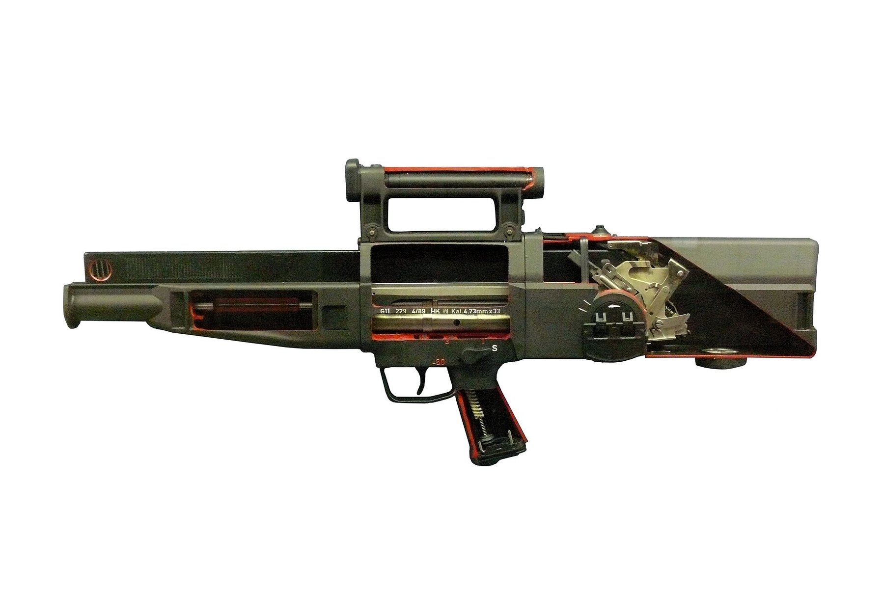
4.1 Scope of this volume
This volume explains how the G11 works at the level of a cycle of operation: which assembly does what, in what order, and why. It does not give dimensions, tolerances, the internal geometry of the burst-counting or trigger mechanism, or any assembly or disassembly procedure. H&K’s armourer’s manual contains a full reassembly sequence with special tools; this volume says that it exists and does not reproduce it. Volume 1 states the dive’s boundary in full.
4.2 The sources
Four documents carry this volume.
- H&K’s armourer’s manual for the ACR rifle. Armorers Manual for Maintenance and Repair of Rifle 4,92 mm, ACR, H&K document TD 2237, marked “1st draft” and dated March 1989, has a “Principle of Operation” section describing the cycle assembly by assembly. It refers to a companion operator’s manual, TD 2236, not found for this dive.1
- H&K and Dynamit Nobel’s English brochure Weapon-Ammunition-System G 11, issued through H&K’s US office in Sterling, Virginia, with technical data and a short description of the floating system and the rotating breech.2 It is advertising, and it is used here for what H&K claimed.
- The US Army’s ACR Final Report, Volume I, of February 1992, whose Appendix B describes the H&K rifle and its problems from the customer’s side.3
- H&K’s US patents 3,997,994 and 4,078,327 of 1976 and 1978, and the placards of the Koblenz study collection (Volume 3).456
Several of H&K’s own brochure and manual illustrations are reproduced here, credited to their source. From the manual, only the drawings of the breech positions and the buffer positions are used; its trigger-mechanism figures and reassembly pages are left out under the dive’s scope. The other diagrams are own work, drawn from the texts at mechanism-schematic level, or drawings by other authors, credited.
4.3 The rifle in numbers
Table 1 — The rifle in numbers
| Item | H&K brochure (G11) | US Army, ACR Final Report (H&K ACR) |
|---|---|---|
| Cartridge | 4.73 × 33 mm caseless | 4.92 mm caseless ball |
| Length | 750 mm | 29.53 in (750 mm) |
| Weight | 3.8 kg with two magazines; 4.3 kg loaded with 90 rounds | 9.15 lb with optic and loaded magazine |
| Barrel length | 540 mm, less chamber | Not given |
| Twist | 155 mm, right hand | 1 in 6 in |
| Magazine | 45 rounds | 45 rounds (H&K’s ACR manual: 50) |
| Modes | Single, 3-round burst, sustained | Semi-automatic, fully automatic, 3-round salvo burst |
| Burst rate | Over 2,000 rounds/min, theoretical | Over 2,000 rounds/min |
| Sustained rate | About 450 rounds/min, theoretical | 600 shots/min |
| Muzzle velocity | About 930 m/s | 3,000 ft/s (914 m/s) |
| Chamber pressure | Mean gas pressure 3,850 bar | 56,000 psi |
| Bullet | 3.25 g | 51 grains (3.3 g) |
| Maximum shoulder force | About 160 N in burst; about 110 N in single and sustained fire | Not given |
Sources: H&K brochure; ACR Final Report, Figure 3.1 and Appendix B.23 The ACR figures describe the rifles entered in the US test in 1990; the brochure describes the G11 as H&K marketed it. Where they differ, both are given.
4.4 The major groups
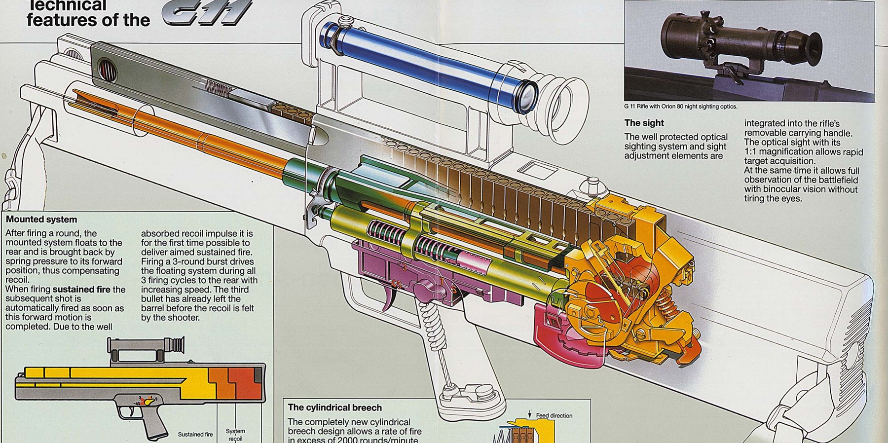
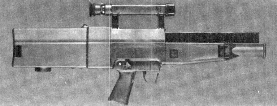
H&K’s manual divides the ACR rifle into a small number of major assemblies, each of which can be removed as a unit.1
- The outer housing. The barrel, the breech mechanism with its counter-recoil system, and most of the magazine sit inside “an outer housing constructed from tough impact resistant material”, which protects “critical parts of the weapon … from mud, sand and water”.1
- The centre part. One piece combining the carrying handle with the integral optical sight, the pistol grip, a centre guide on which the moving assembly slides, and the trigger mechanism. Inside it is a “system locking lever” that holds the breech and barrel assembly forward until the trigger releases it.1
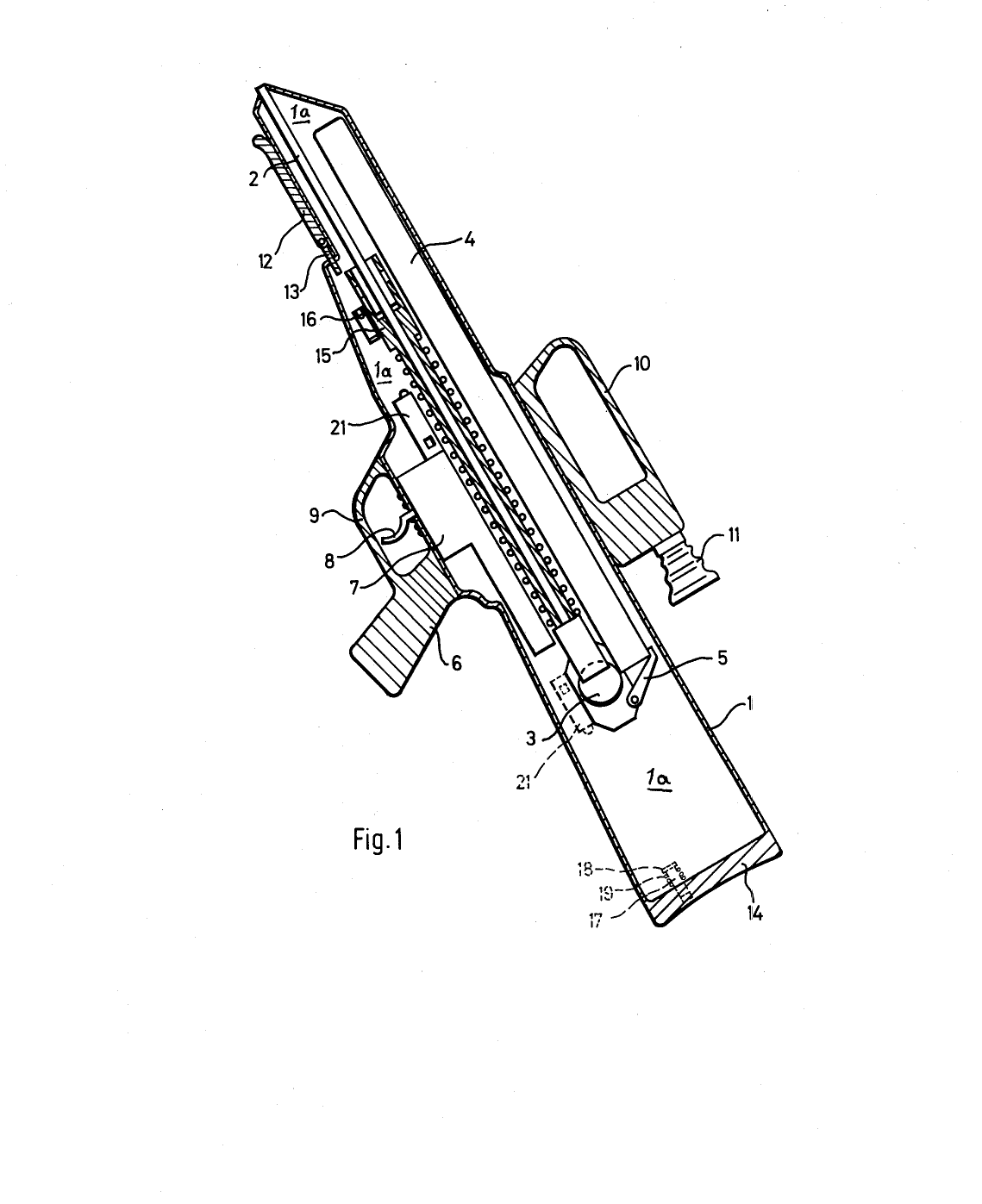
- The breech and barrel assembly. “The breech cylinder housing, barrel, counter recoil mechanism, and gas system are one complete assembly.” It slides back and forth on the centre guide when the rifle fires.1 This is the floating system.
- The counter-recoil mechanism. A buffer assembly whose front is locked to the centre part and whose rear moves with the breech and barrel assembly; the US Army calls it a hydraulic unit (below).13
- The magazine. A single-row box “inserted … above the barrel and parallel to it”, withdrawn forwards, with the rounds lying nose-down and a window in which a red coil of the spring shows roughly how many are left.1
- The buttstock. It carries the cocking handle, which is rotated through a full turn rather than pulled, a bottom ejection port for clearing an unfired round, a magazine release, and a “high pressure vent” that stops propellant gas building up inside the sealed housing.1
4.5 The round, briefly
The hub’s Daisy dive, Volume 15 covers caseless ammunition in general. For the G11’s mechanism, four features of its round matter:
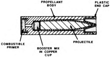
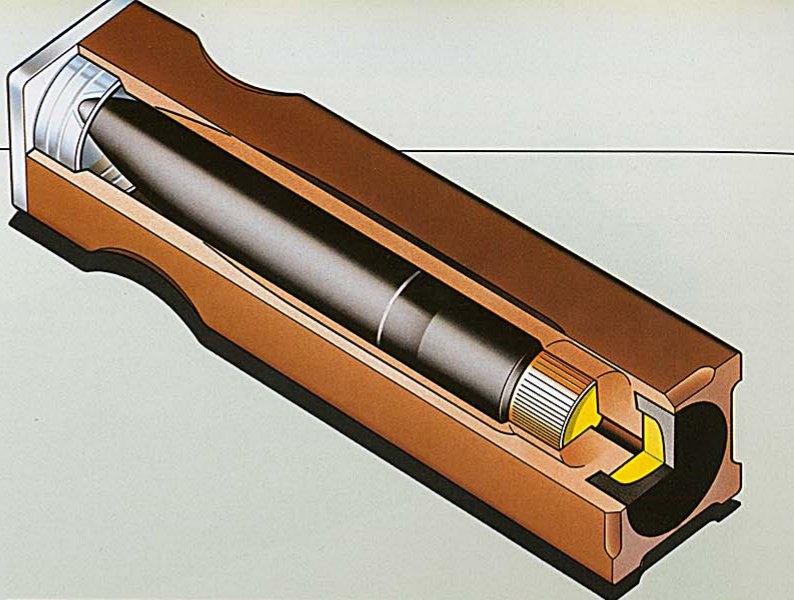
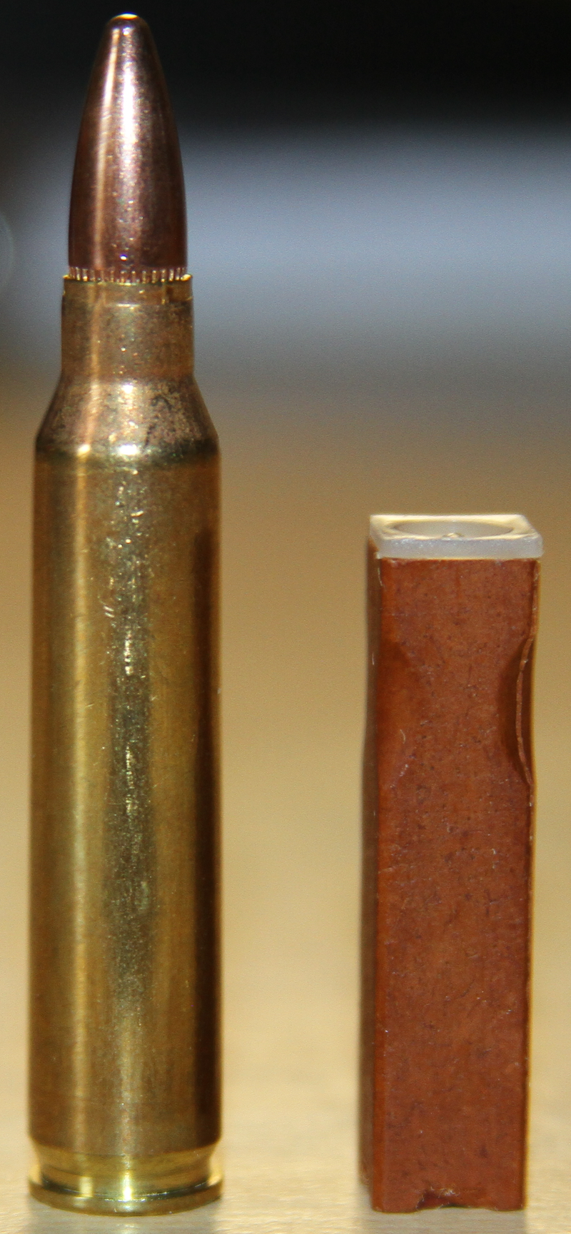
- It is square. The propellant body has a square cross-section, which H&K said avoided “unused space in packages and magazines”.2 The US Army added that it carries “an indentation at the front end to permit front end identification without direct vision”.3
- The bullet is inside it. “The projectile (bullet) is completely surrounded by the propellant body and is protected by a plastic cap.”1
- It ignites from the bottom up. An impact-sensitive primer at the base fires a booster under the bullet; the booster drives the bullet forward into the barrel’s forcing cone, sealing the chamber, before the main propellant body burns. “The bullet is pushed through the plastic cap into and through the barrel. The plastic cap exits the barrel behind the bullet.”13 The booster’s copper cup also leaves through the muzzle.3
- Nothing comes out of the breech. All of the round except the plastic cap and the copper cup is consumed, so the mechanism never has to extract a case. That is what made a 2,000-round-a-minute burst mechanically possible: “Its caseless ammunition eliminates the need for an extraction cycle during firing allowing its salvo burst to be fired at over 2,000 rounds a minute.”3
4.6 The cycle, step by step
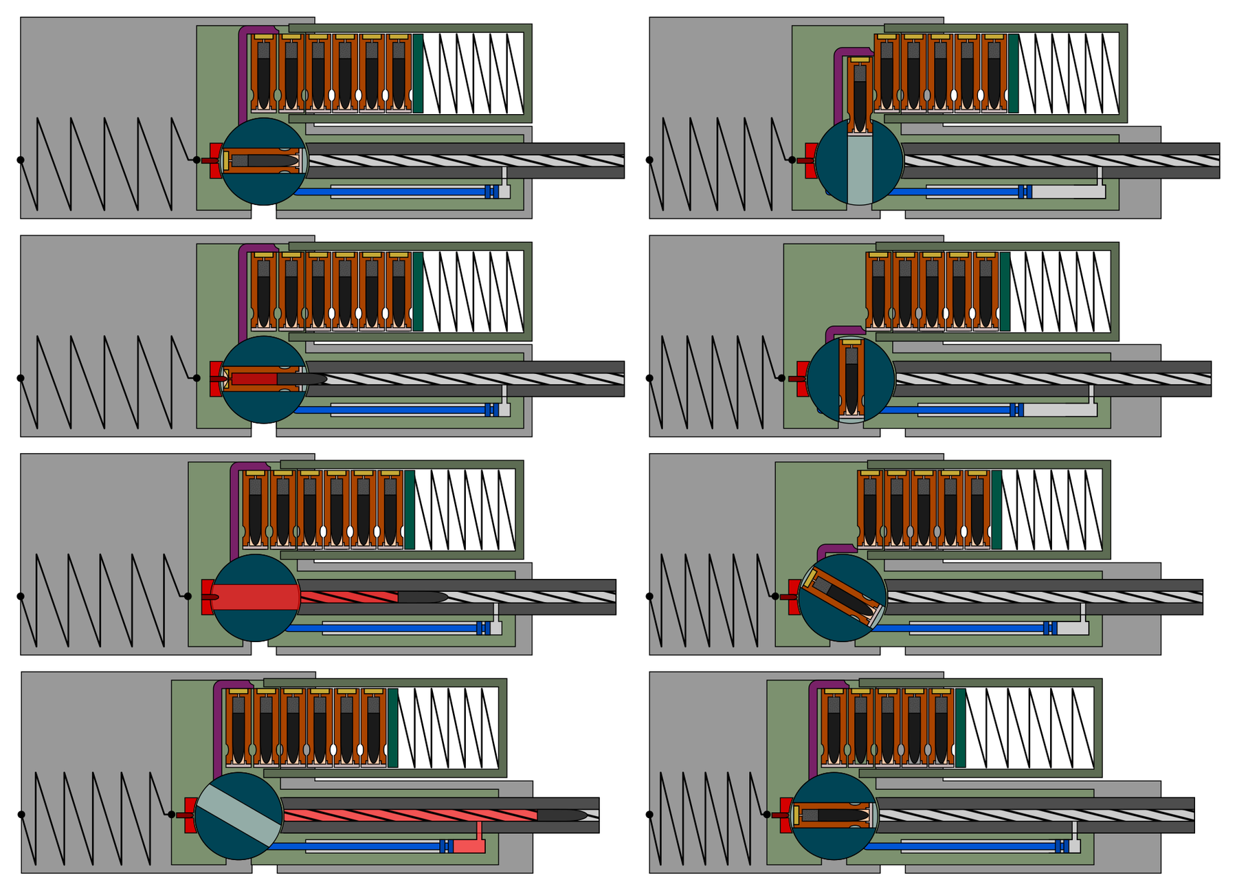
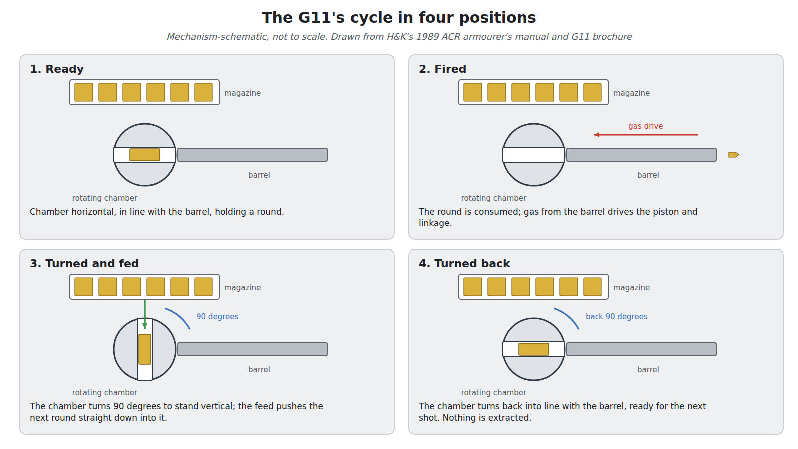
The manual describes the cycle in terms of a few moving parts, all driven by one gas piston. In outline:12
- Ready to fire. The breech cylinder, a cylinder with the chamber bored across it, sits with its chamber horizontal, in line with the barrel, holding a round. The striker is cocked. The breech and barrel assembly is held at the front of its travel.
- Firing. The trigger releases the breech and barrel assembly to move rearward and releases the striker, which turns a rotary firing pin against the primer. The booster drives the bullet into the forcing cone; the propellant body burns.
- Gas operation. Once the bullet passes a gas port in the forward part of the barrel, gas drives a piston rearward against its return spring. A connecting rod fixed to the piston turns an actuating gear; the manual compares the linkage to “the drive wheel of a steam locomotive”.
- Chamber to feed position. Through a spur gear and cams, the gear rotates the breech cylinder 90 degrees so that the chamber stands vertical, open towards the magazine above. A stop lever holds it there.
- Feeding. As the chamber reaches the vertical, a feeding lever driven from the same spur gear rises over the first round in the magazine, then moves down, pushing the round straight down out of the magazine into the chamber. A slide stops the round from passing through and positions it.
- Chamber to firing position. The stop lever releases, and the gear turns the breech cylinder 90 degrees back to the horizontal. The rotation also re-cocks the striker.
- Next shot or rest. What happens next depends on the mode selected (below).
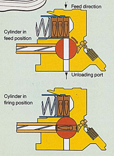
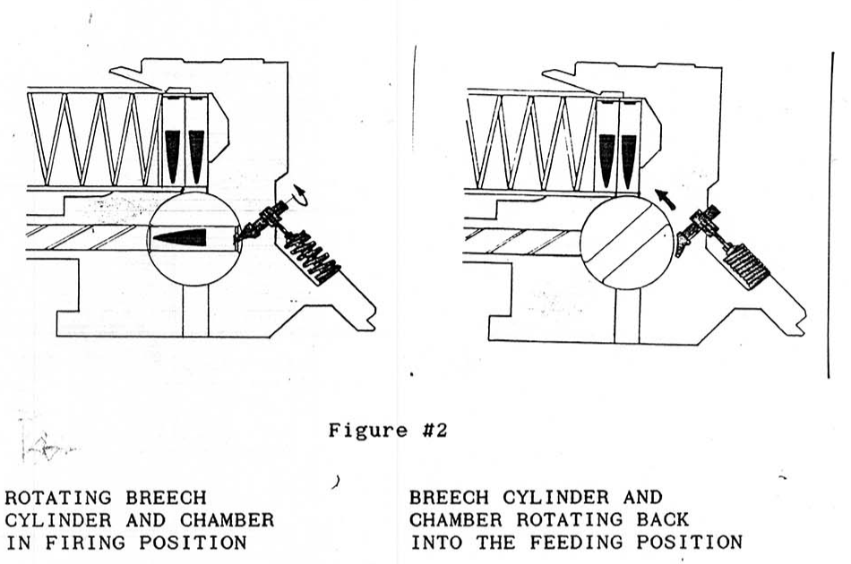
The manual’s description of feeding explains why the G11 could cycle so fast. Each round travels a very short, straight path, down from the magazine into a chamber that comes to meet it, and nothing has to be pulled back out. H&K’s brochure says the same: “This high cadence is only possible because of the short, absolutely straight cartridge feed into the vertically positioned chamber.”2 The US Army’s description is sharper about the demand this places on the parts: in the burst the chamber “must accept a round, rotate exactly ninety degrees to be in line with the barrel, fire the round and obturate the mechanism to seal the chamber, then counter-rotate exactly ninety degrees again to be in the loading position at over 2,000 times a minute. The weapon has long ago demonstrated its ability to perform just as described.”3
4.7 Why a rotating chamber
The rotating chamber is the G11’s most distinctive feature, and the US Army’s report gives the most plausible reason for it. With caseless ammunition there is nothing to grip and pull out of the chamber if a round fails to fire or breaks. “Originally, it is believed that the design departed from more standard linearly reciprocating mechanisms due to the difficulties envisioned with the extraction cycle for duds, misfires, broken rounds, etc. There was no simple, reliable method envisioned to remove a round or fragments if that were necessary. The rotary chamber, conversely, did offer a method whereby this extraction might take place reliably.”3
The method is to push rather than pull. To clear a dud, the firer turns the cocking handle; the chamber rotates to the vertical, and the next round coming down from the magazine pushes the dud or its fragments out through the bottom of the chamber and through a port in the bottom of the housing, whose cover opens at that moment.31 With no magazine fitted, an ejector does the pushing instead.1
The patent of 1974 to 1976 adds two engineering reasons. A swivelling roller is “only one single moving part”, needing only a cylindrical hole to sit in, and if the chamber’s axis passes through the roller’s axis the roller is “approximately balanced”, so the gas pressure produces no moment tending to turn it out of line during the shot.4
The cost was complexity in everything around the chamber. The US Army’s summary is that “Virtually every other innovation was developed to compensate for the rotary chamber’s unique requirements.”3 Sealing a rotating chamber against the gas of each shot took years of redesign, described in the report and not reproduced here, and the cam plate and levers that rotate the breech cylinder are, in the Army’s words, “the basic source of the weapon’s complication”.3
4.8 The floating system
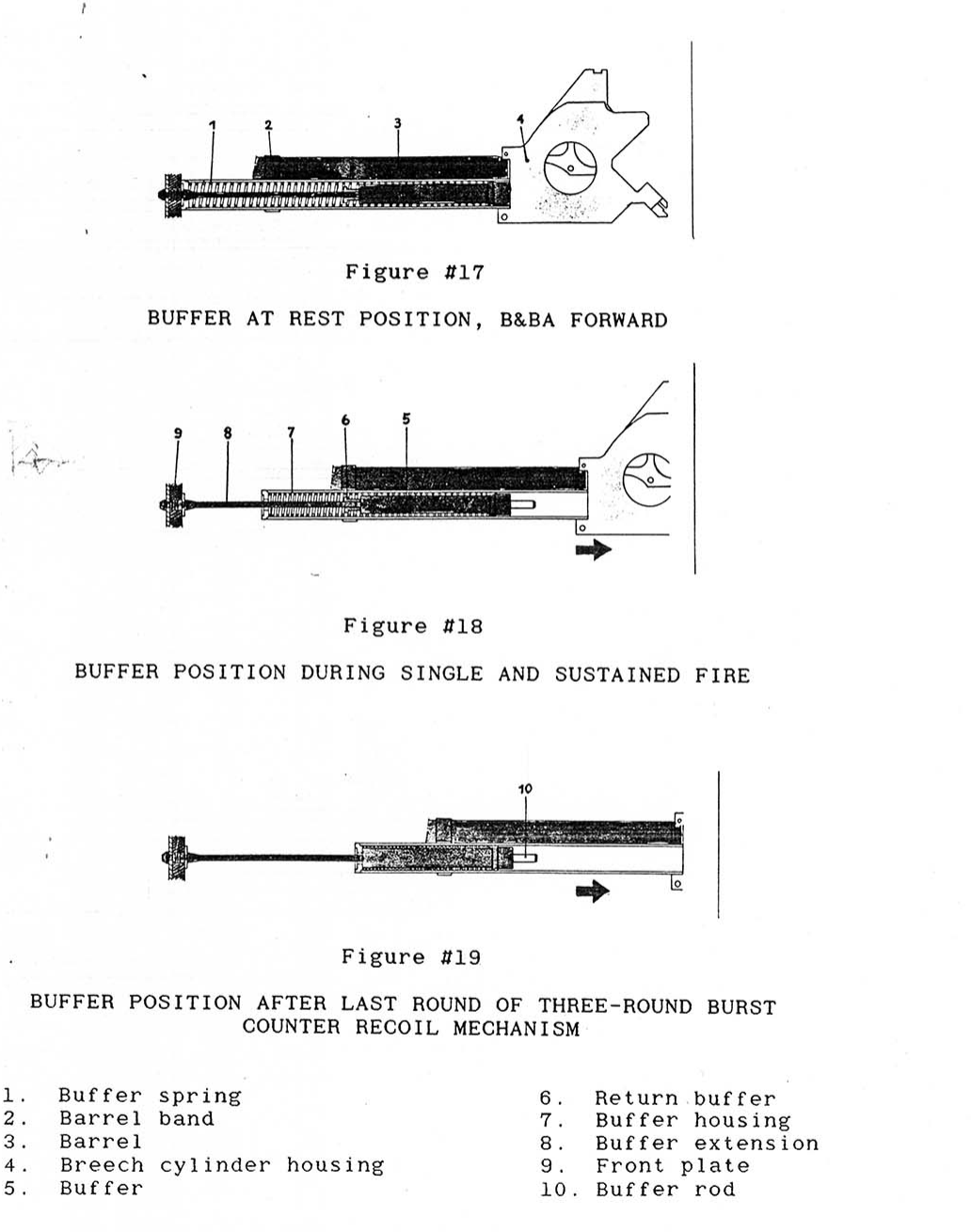
The burst works because of the counter-recoil mechanism. H&K’s manual describes it in three sentences: the breech and barrel assembly “is free to move horizontally back and forth in the center part by sliding on the center guide”; “When a round is fired, the B&BA is pushed rearward by the recoil impulse”; and the buffer spring, compressed as the assembly moves back, damps the movement and pushes the assembly forward again.1
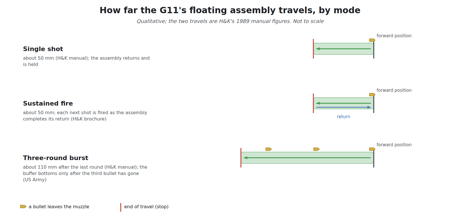
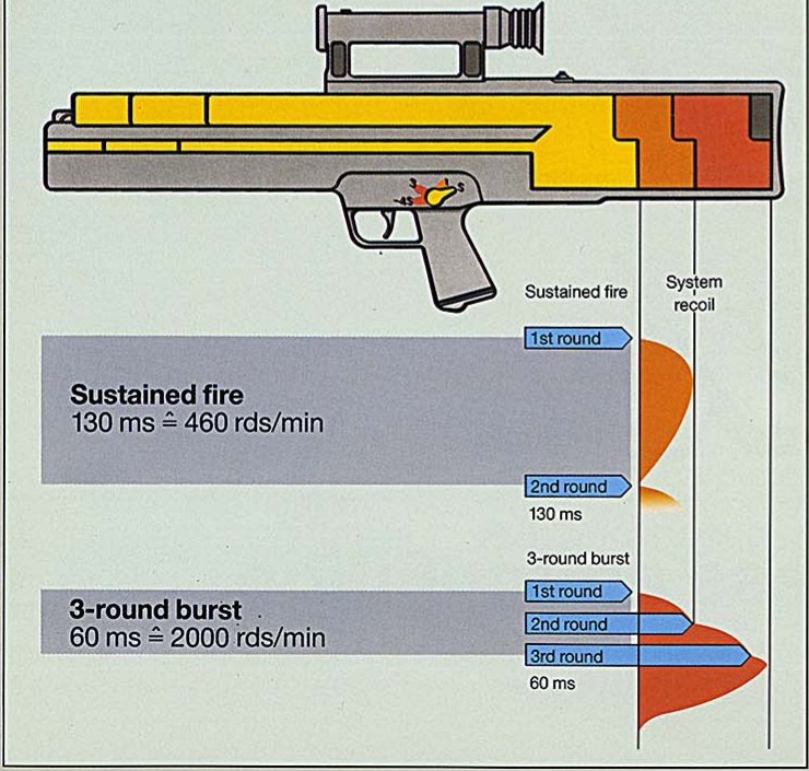
The key fact is how far the assembly is allowed to move in each mode. In single and sustained fire, the manual says, the rearward movement “is ended after 50 mm (2”) of travel”. In the three-round burst, “the B&BA has moved rearward approximately 110 mm … after the last round is fired”, and a return buffer damps the impact at the end of that longer travel.1 The assembly is allowed to travel roughly twice as far in a burst as in a single shot, because it has to absorb three recoil impulses before it stops.
H&K’s brochure states the result: “Firing a 3-round burst drives the floating system during all 3 firing cycles to the rear with increasing speed. The third bullet has already left the barrel before the recoil is felt by the shooter.”2 The US Army, which called the arrangement the “internal operating floating system” (IOFS), confirmed it from its own testing:
“This hydraulic unit allows the entire recoiling mass (breech and barrel assembly) to recoil differing distances depending on the mode of fire selected. There is the minimum recoil in semi auto, limited recoil in the relatively slow (600 spm) full auto mode, and the maximum recoil while firing the three round salvo burst. Adequate testing has been done to prove that, in the salvo mode, each recoil force peak is substantially reduced relative to the M16 rifle. While firing in this mode, the buffer does not reach its rearmost point of travel until after the third projectile has exited the muzzle.”3
That last sentence is the hyper-burst principle demonstrated. The ACR report’s summary of the H&K rifle calls the IOFS with its hydraulic buffer “probably” the most important of its novel technologies, “which allows the third round of a high rate salvo burst to leave the muzzle before the shooter can feel the recoil impulse.”3
In sustained fire the floating system was used differently. H&K’s brochure says that after each shot “the mounted system floats to the rear and is brought back by spring pressure to its forward position, thus compensating recoil. When firing sustained fire the subsequent shot is automatically fired as soon as this forward motion is completed.”2 In other words, the automatic rate was governed by the floating assembly’s full return, which is why it was so much lower than the burst rate. H&K’s brochure gives the time for a sustained-fire cycle as 130 milliseconds, or about 460 rounds a minute; Der Spiegel reported the burst at 30 milliseconds a shot.27
H&K also published the force on the shoulder: about 160 newtons in the burst and about 110 in single and sustained fire.2 Those are H&K’s figures, not measurements found in any independent report. The US Army’s statement that each recoil peak was “substantially reduced relative to the M16” is the independent confirmation, without a number.3
4.9 Three modes, three rates, three sets of figures
Table 2 — Three modes, three rates, three sets of figures
| Source | Three-round burst | Sustained (automatic) fire |
|---|---|---|
| WTS placards, Prototype 1 and 2 (1974 to 1975) | 1,800 rpm | 400 rpm |
| WTS placard, Prototype 13 (1979) | 2,000 rpm | 500 rpm |
| WTS placards, Prototype 14 to K 2/3 (1984 to 1990) | 2,000 rpm | 550 rpm |
| Der Spiegel, 1982 and 1987, quoting H&K | 30 ms per shot | Not given |
| H&K brochure | Over 2,000 rpm (theoretical); 60 ms label on the timing diagram | About 450 rpm (theoretical); 130 ms, 460 rpm on the diagram |
| US Army, ACR Final Report (1992) | Over 2,000 rpm | 600 spm |
Sources: WTS placards; Spiegel 19/1982 and 31/1987; H&K brochure; ACR Final Report.6723
The burst figures agree. The sustained-fire figures range from 400 to 600 rounds a minute across the prototypes and sources, and they are not averaged here. The hub’s Daisy dive, Volume 12, gives the same three figures for the G11’s automatic fire.
The burst itself is limited mechanically. In the burst position, the manual says, the first round fires as in single fire and “the remaining rounds of the burst are automatically fired by command from the three-round counting mechanism. The burst is automatically stopped after the third round is fired.”1 How that counting mechanism works is outside this dive’s scope.
4.10 The gas inside the housing
The G11’s sealed housing created a problem that no conventional rifle has, and the record of it runs through all four primary sources.
A caseless chamber does not seal at the instant of firing. The US Army explained that the chamber “does not fully obturate until the internal pressure has built to some hundreds of psi (400-500). Until full obturation occurs, there is a gas path from the chamber to the interior of the plastic housing. There is also a corresponding spark path.” Combustion leaves carbon monoxide and hydrogen, so “it becomes intuitive that eventually, an explosive mixture will accumulate within the housing.”3 Pressure-relief valves could hold the housing at about a quarter of a pound per square inch before ignition, but “after spark initiation of the explosive gas mixture, no relief valve will act quickly enough to vent the burning gases”. Letting air in to keep the mixture lean would also let water in.3
The Koblenz placard for Prototype 13 of 1979 records what that meant in practice: “Die unvermeidlichen Verpuffungen im Waffeninneren führen jedoch zu plastischen Verformungen des Stahlblechgehäuses”, the unavoidable deflagrations inside the weapon deformed the sheet-steel housing.6
H&K had already patented one answer. US 4,078,327, filed in 1976, describes an ignition device inside the sealed receiver that deliberately burns the accumulating gas “at predetermined times”, ideally “after every shot or burst”, so that only small quantities ever ignite, and notes “a surprising advantage”: after a few ignitions the oxygen in the housing is used up and the mixture no longer ignites at all. The patent rejected batteries, which would not survive years of storage, and flints, which give too little spark, in favour of piezoelectric crystals struck by a part of the gas-operated action.5
By 1989 H&K had chosen a different answer, according to the US Army: it “elected to re-design the housing to withstand these recurring initiations”, and fitted an opening with a one-way pressure-relief valve under a wire mesh “to prevent burns after a gas initiation has occurred”. The Army’s comment was that “These design features undoubtedly perform as intended, but the basic sealed design has forced these further complications to an already complex weapon.”3 H&K’s own manual of the same year lists the buttstock’s “high pressure vent”, which “prevents the build-up of high-pressure propellant gas within the tightly-sealed outer housing”.1
4.11 Cook-off: the record, not the brochure
H&K’s brochure said: “The risk of cook-off is largely eliminated by the extremely high self-ignition temperature of the propellant.”2 The US Army’s account is more detailed and less reassuring.3
- A cook-off test in March 1986 showed resistance to cook-off for 100 rounds fired at both 85 and 325 shots a minute, with the 101st round left chambered.
- Making the interior ballistics reproducible later required a deliberately slow and uniform start to each shot. That increased the time for burning gas to heat the chamber about fourfold, “The cook-off level dropped to 1/4, or 25 rounds.”
- Continued work “re-established a cook-off performance level of 100 shots fired at 85 spm without cook-off of the 101st round.”
- For the safety release before the 1990 field experiment, the Army’s Combat Systems Test Activity tested at 35 shots a minute, “the estimated cyclic rate to be tested in the field experiment”, and found a cook-off level “of greater than 135 shots fired without cook-off”. The rifle was restricted to 135 rounds, three magazines, before cooling during the field trials.
The Army’s general conclusion was nonetheless positive: “Few problems were experienced with the caseless rifles in the test. The past technical barriers of cook-off and vulnerability have now been overcome.”3 Both statements are the Army’s. The 1990 record shows cook-off managed by a firing limit rather than eliminated, as the hub’s Daisy dive, Volume 12, also says.
On vulnerability, the Army described a videotape of armour-piercing rounds fired into a magazine of live H&K rounds: no initiation unless the primer itself was struck, and then only a “slow fire” that burned until the rounds were consumed, leaving the mechanism “very dirty” but functional.3
4.12 Sights, controls and handling
- Optic. H&K’s brochure shows a 1× sight in the carrying handle with a 200-mil field of view.2 The ACR rifle’s sight was made by Swarovski Optik of Innsbruck and switched between 1× and 3.5×, with stadia lines for range estimation beyond 300 m and settings for 300 to 600 m. It had no backup iron sight; H&K declined to make the sight removable because its plastic housing, without a metal backing, “would likely not permit zero retention.”3 The final German K 2/3 standard did have a removable optic, according to the Koblenz placard.6
- Magazine as pointing aid. The magazine on top carries a white line for pointing in quick fire.13
- Charging. The cocking handle is folded out and turned through a full turn; turning it chambers a round, cocks the mechanism, and with no magazine fitted ejects a chambered round through the bottom port.1
- Firing pin. The ACR rifle used a rotating firing pin driven by a rack and pinion and a stab-type primer containing ground glass as an anvil; the Army noted that a rotating shaft is far easier to seal against gas than a pin that slides.3
- Symmetry. The mechanism was built “bi-laterally symmetric so that as the weapon heats and expands, there are no bending or twisting moments.”3
- Extra magazines. The ACR rifle’s 45-round magazine was long; H&K developed a 25-round half-length magazine, not tested in the field experiment.3 The German K 2/3 instead carried two or three full magazines on the rifle.6
4.13 Maintenance and repair, as documented
The brief for this hub asks every dive for field strip, detail strip, maintenance and repair. For the G11 the documentary record is unusual, and this dive’s scope boundary applies. What the sources show:
- The soldier was not expected to open the mechanism. “As the mechanism is so very complex, H&K has decided that the soldier will not normally open the plastic housing of the weapon except for cleaning. During cleaning, the weapon is broken down into major sub-assemblies but not fully disassembled.”3
- Armourer and depot levels were separate. H&K’s armourer’s manual, a first draft of March 1989, covered armourer’s disassembly and reassembly, cleaning, gauging and inspection and troubleshooting, with special tools including a control-disk wrench, barrel vice blocks and an assembly fixture for the buffer. It reserved “depot level maintenance, such as barrel replacement” to the manufacturer: “Only the manufacturer is authorized at this time to perform any and all depot level maintenance procedures.”1 The procedures themselves are not reproduced in this dive.
- Field reliability. The US Army judged the mechanism “highly reliable, with minimum weapon related stoppages or other form of malfunction traceable to the weapon mechanism. The majority of the malfunctions/stoppages experienced in the field experiment were ammunition related.”3
- Parts and repair today. No G11 or ACR rifle is in service anywhere, no spare parts are sold, and the surviving rifles are museum and institutional pieces. Volume 7 covers ownership.
4.14 Where the documents disagree
Table 3 — Where the documents disagree
| Point | One source | The other | Note |
|---|---|---|---|
| Magazine capacity, ACR rifle | 45 rounds (US Army report) | 50 rounds (H&K ACR armourer’s manual) | Both 1989 to 1992; the manual is a first draft |
| Sustained rate | About 450 rpm (H&K brochure) | 600 spm (US Army); 550 rpm (Koblenz placards) | Not averaged |
| Cook-off | ”Largely eliminated” (H&K brochure) | Limited to 135 rounds before cooling in the 1990 trials (US Army) | The Army also says the barriers were “overcome” |
| Removable optic | Not removable on the ACR rifle (US Army) | Removable on the German K 2/3 (Koblenz) | Different standards |
| Calibre name | 4.73 × 33 (H&K, Bundeswehr) | 4.92 mm (US Army) | The same round family under two naming conventions |
References
Footnotes
-
Heckler & Koch, Armorers Manual for Maintenance and Repair of Rifle 4,92 mm, ACR, TD 2237, first draft, March 1989, sections “Operation: Technical Description” and “Principle of Operation”. Copy in the Internet Archive item “G11 Manual and references”, https://archive.org/details/1557677285551-2, consulted 2026-10-18. Figures 2 and 17 to 19 reproduced; trigger-mechanism figures not reproduced. ↩ ↩2 ↩3 ↩4 ↩5 ↩6 ↩7 ↩8 ↩9 ↩10 ↩11 ↩12 ↩13 ↩14 ↩15 ↩16 ↩17 ↩18 ↩19 ↩20
-
Heckler & Koch and Dynamit Nobel (GHGS), Weapon-Ammunition-System G 11: the new weapon-ammunition-system with caseless ammunition for high hit probability, English brochure with the address of Heckler & Koch, Inc., Sterling, Virginia, undated (print code read as 10.88). Copies in the Internet Archive items https://archive.org/details/1557677285551-2 and https://archive.org/details/gunmanual_Hk_G11, consulted 2026-10-18. ↩ ↩2 ↩3 ↩4 ↩5 ↩6 ↩7 ↩8 ↩9 ↩10 ↩11 ↩12
-
Vernon E. Shisler and Stephen M. Mango, Advanced Combat Rifle (ACR) Program, Volume I, ACR Program Summary, ARCCD-TR-92001, US Army ARDEC, Picatinny Arsenal, February 1992, sections 3.4 and 8.0 and Appendix B, section 1.2.2 (DTIC AD-B162 942). Public digitised copy, https://municion.org/wp-content/uploads/2022/11/06-047-BGC-011-1.pdf, consulted 2026-10-18. ↩ ↩2 ↩3 ↩4 ↩5 ↩6 ↩7 ↩8 ↩9 ↩10 ↩11 ↩12 ↩13 ↩14 ↩15 ↩16 ↩17 ↩18 ↩19 ↩20 ↩21 ↩22 ↩23 ↩24 ↩25 ↩26 ↩27 ↩28 ↩29
-
US Patent 3,997,994, G. Kästner, D. Ketterer, T. Möller and E. Wössner, assignors to Heckler & Koch GmbH, “Shoulder Arm with Swivel Breech Member”, issued 21 December 1976. https://patentimages.storage.googleapis.com/pdfs/US3997994.pdf, consulted 2026-10-18. ↩ ↩2
-
US Patent 4,078,327, T. Möller and D. Ketterer, assignors to Heckler & Koch GmbH, “Automatic or Semi-Automatic Small Arm”, issued 14 March 1978. https://patentimages.storage.googleapis.com/pdfs/US4078327.pdf, consulted 2026-10-18. ↩ ↩2
-
Wehrtechnische Studiensammlung, Koblenz, G11 display placards (Prototypes 1, 2, 3, 13 and 14; Konstruktionsstand 1; Konstruktionsstand K 2/3), read from Wikimedia Commons photographs by Clemens Vasters (2017, CC BY 2.0) and Bojoe (2009, CC BY 3.0). Consulted 2026-10-18. ↩ ↩2 ↩3 ↩4 ↩5
-
“Gedämpftes Pressen”, Der Spiegel 19/1982, 9 May 1982, https://www.spiegel.de/spiegel/print/d-14350537.html, consulted 2026-10-18. ↩ ↩2
Comments (0)