Smith & Wesson Model 41 · Volume 3
How It Works: an Exposed Barrel, a Short Slide, and a Trigger Guard That Holds the Barrel On
Straight blowback, why both sights ride on the barrel, the 1957 barrel-latch and trigger-spring patents read part by part, and what the trigger, safety and stop actually do
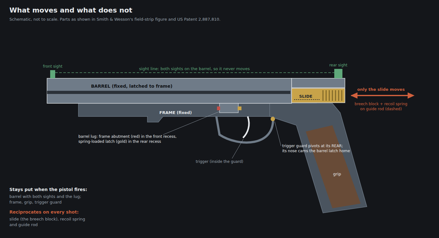
The Model 41 looks like a slide-action semi-automatic pistol of the ordinary kind until it is taken apart. It is not. Its barrel is not inside its slide, its sights are not on its slide, and nothing holds its barrel to its frame except its trigger guard. This volume describes the mechanism from the two primary sources available for it: Smith & Wesson’s own manuals, which describe what the owner sees and does, and two patents Smith & Wesson took out in 1957, which describe how the barrel is held and how the trigger spring was meant to work. Where neither source reaches, this volume says so rather than filling the gap from a disassembly video.
3.1 The Layout in One Paragraph
Smith & Wesson’s field-stripping figure shows the pistol in five pieces: barrel, slide, recoil spring, spring guide rod, and frame assembly.1 The barrel is a long single piece. Its forward part is the barrel proper, with the front sight at the muzzle; its rearward part is an extension that runs back over the slide and carries the rear sight, and underneath it hangs a lug with a recess at each end. The slide is short: a breech block with serrations for the fingers, a channel for the recoil spring and its guide rod, and the breech face. It runs on tracks in the frame beneath the barrel’s rear extension. The frame carries the grip, the trigger, the lockwork, the magazine well, the thumb safety, the slide stop and a trigger guard that pivots at its rear end. Pull the guard down and the barrel lifts off.
3.2 Straight Blowback, and Why a .22 Can Use It
The Model 41 is a straight blowback. Smith & Wesson’s manual describes the cycle without using the word: the trigger releases the hammer, the hammer strikes the firing pin, “the slide moves rearward thereby extracting and ejecting the spent cartridge case”, and “the slide then returns forward feeding the next cartridge from the magazine into the barrel chamber”.1 Nothing locks the breech. The slide is held against the cartridge head only by its own inertia and by the recoil spring.
That is the whole design argument for the action, and it depends on the cartridge. When a round fires, pressure drives the case rearward against the breech face with a force equal to chamber pressure times the area of the case head. A locked breech holds the case until pressure has fallen. A blowback holds it only by making the breech block heavy enough, and the spring strong enough, that the block has barely begun to move by the time the bullet has left the muzzle and pressure has collapsed. For a cartridge with a small case head and a modest pressure, a slide of hand-operable weight and a spring a shooter can rack easily do that job. The .22 Long Rifle is that cartridge, which is why nearly every .22 semi-automatic pistol, from the High Standard and the Ruger Mark series to the Model 41, is a blowback.
Two consequences follow, and both come back in Volume 6.
- The slide’s mass and the spring are tuned to a cartridge’s impulse. A heavier-than-intended impulse drives the slide back harder than the design assumed; a lighter one may fail to cycle it. That is the mechanical reason a blowback target pistol is sensitive to what it is fed, and the reason the .22 Short Model 41-1 needed a lighter slide (Volume 2).
- The case is moving while pressure is still present. Early extraction under residual pressure is normal in a blowback; it is also why chamber cleanliness matters to extraction, which the manual addresses directly (Volume 6).
No published figure was located for the Model 41’s slide mass, recoil-spring rate or bolt travel, and none is estimated here.
3.3 What Moves and What Does Not
The Model 41’s defining feature is that the part that moves is not the part that aims.
On a service-type pistol, the rear sight rides on the slide. The slide reciprocates on every shot, and its fit to the frame and the barrel’s fit to the slide together decide where the rear sight is when the next shot breaks. On a Model 41, the rear sight and the front sight are both on the barrel, and the barrel is latched to the frame. The slide moves under the barrel’s rear extension; the sight line does not move at all. Smith & Wesson’s field-stripping figure shows exactly this: the rear sight is on the barrel piece, not on the slide piece.1
The benefit is stated in the service literature of the period for a comparable design. The joint Army–Air Force match-weapons manual of 1959 says of the Ruger Mark I Target that its rear sight “is attached to the receiver and does not move with the recoil action of the weapon”.2 The Model 41 reaches the same result by a different route, putting the rear sight on the barrel rather than on a receiver tube, and adds a second benefit: because both sights are on the same piece of steel as the bore, the sight radius and the sights’ relationship to the bore travel with the barrel when barrels are changed. A 5.5 in barrel and a 7 in barrel each bring their own sights. The sight settings on each barrel are therefore that barrel’s settings, not the frame’s.
The cost is weight forward and a pistol that is barrel-heavy by design. For bullseye shooting that is not a cost; Volume 1 explains why a one-handed rapid-fire pistol wants it.
3.4 The Barrel Latch: US Patent 2,887,810
On 28 May 1957, Joseph W. Norman of Springfield, Massachusetts filed an application, assigned to Smith and Wesson, for a “Firearm Barrel Latch”. It was granted on 26 May 1959 as US Patent 2,887,810.3 It is the document that describes, in Smith & Wesson’s own name, how a Model 41 barrel is held on.
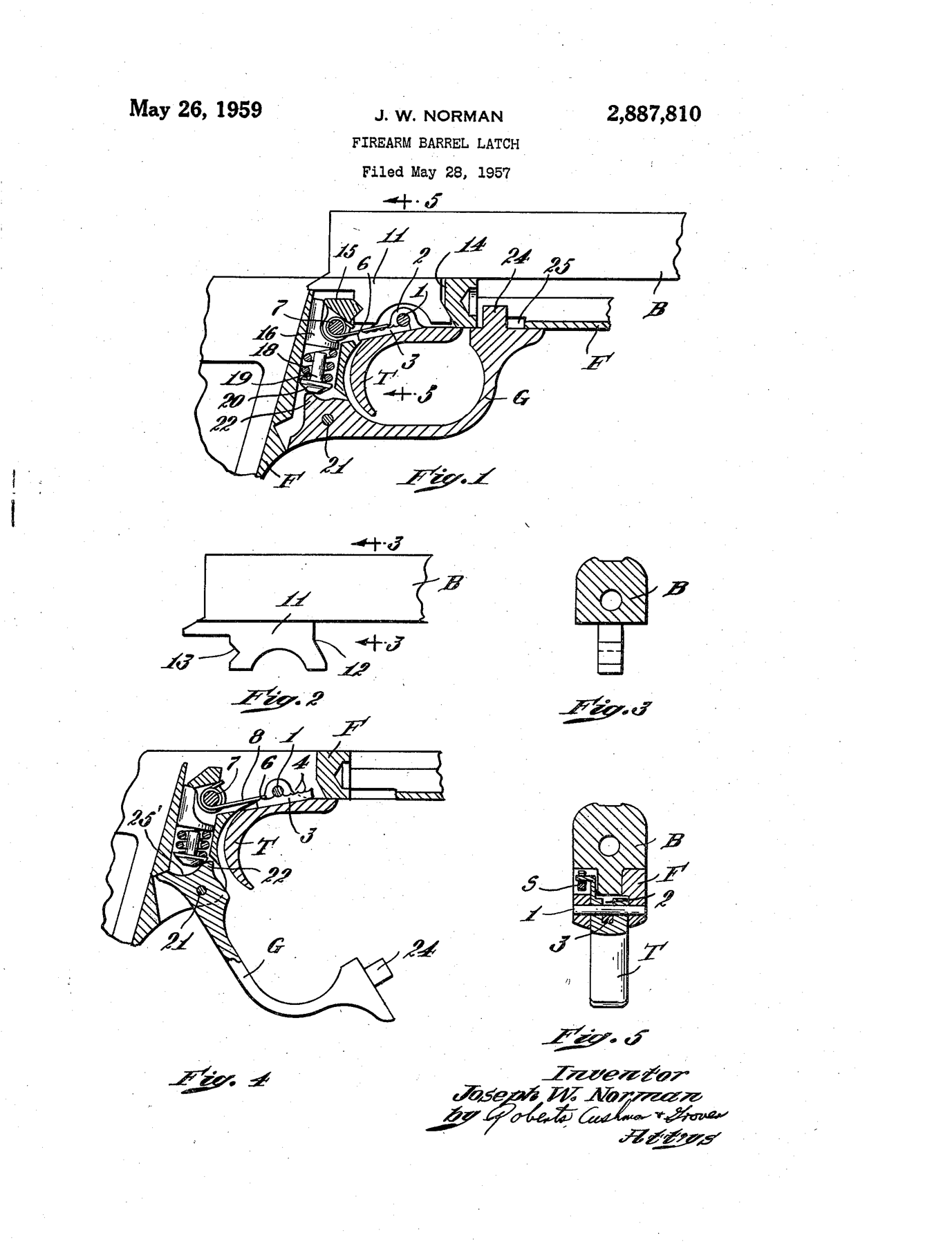
The patent states its objects in terms any owner will recognise. The barrel should be “readily detachable”, the means “simple and economical in construction”, able to be “operated quickly and easily”, “completely concealed within the frame”, and “durable and reliable in use”. It dismisses the existing schemes: “they have not been satisfactory for various reasons, chiefly because they are difficult to operate or do not hold the barrel securely.”3
The parts, with the patent’s own reference numbers:
Table 1 — The parts, with the patent's own reference numbers
| Part | Patent no. | What it does |
|---|---|---|
| Barrel lug | 11 | Hangs beneath the barrel, “over the trigger”; has a forward recess (12) and a rear recess (13) |
| Frame abutment | 14 | A fixed part of the frame that enters the lug’s forward recess |
| Latch | 15 | Pivoted on pin 7; swings into the lug’s rear recess |
| Plunger, coil spring, pin with head | 16, 18, 19/20 | Transmit a spring load to the latch |
| Trigger guard | G | ”Pivotally mounted on the frame by means of a pin 21” near its rear end |
| Guard nose | 22 | Bears on the pin’s head (20). With the guard closed, “the nose 22 forces the pin 19 upwardly to compress the spring 18, thereby forcing the latch 15 into latching position … the nose 22 functioning as a cam” |
| Guard front lug | 24 | Enters an opening (25) in the frame when the guard is closed |
Mounting the barrel, in the patent’s words: “the lug 11 is inserted into the frame, the barrel is moved forwardly until the abutment 14 seats in the forward recess 12 and the trigger guard is then swung to closed position to press the latch 15 into the rearward recess 13.” Removing it: “the barrel may be quickly and easily removed merely by swinging the trigger guard to open position and then lifting the barrel from the frame.”3
Three things follow from reading it rather than a summary of it.
- The barrel is trapped fore and aft, not clamped. The frame abutment in one recess and the latch in the other capture the lug between them. What holds the latch in is a coil spring, compressed by a cam, not a screw. This is why the barrel comes off without tools, and why the barrel’s return to zero after removal depends on the lug, the abutment and the latch, not on how hard anything was tightened.
- The trigger guard is a load-bearing part. Its nose is the cam that loads the latch spring. A bent or damaged guard, or debris between the nose and the pin head, is not a cosmetic problem.
- The patent’s order is the manual’s order. Smith & Wesson’s field-strip sequence (Volume 6) is: lock the slide open, rotate the trigger guard down, lift off the barrel, then remove the slide. The barrel has to come off first because its rear extension lies over the slide.
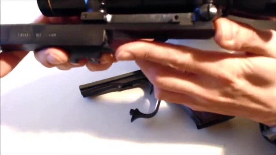
The same arrangement appears, drawn with different reference numbers, in the companion trigger-spring patent filed the same day, and it is plainly visible in a video still of a Model 46 being taken down: the plainer model used the same latch.
3.5 The Trigger
The Model 41 is single action only. Its lockwork, as the manual describes it, is a trigger that releases an internal hammer, which strikes a firing pin in the slide.1 The manual adds the disconnector’s effect without naming the part: “After firing you must allow the trigger to move forward fully before you can fire another shot. Failure to do so will prevent the lockwork from fully cycling and will prevent your being able to fire the next shot.”1
Smith & Wesson’s current specification is a “Crisp Target Trigger Factory Set at 2.75 to 3.25 lbs.” with a “User Adjustable Trigger Stop”.4 A reviewer measuring one in 2016 reported “a crisp 2.7 to 3 lb. trigger pull with almost no over-travel”.5 The NRA’s current minimum for the .22 stage of Precision Pistol is 2 lb (Volume 1).6
No Smith & Wesson document consulted explains how the pull weight is set at the factory, or permits the owner to change it. The manuals’ instruction is categorical: “NEVER MANIPULATE, ADJUST OR CHANGE ANY OF THE INTERNAL COMPONENTS OF YOUR FIREARM UNLESS SPECIFICALLY INSTRUCTED TO DO SO IN THIS MANUAL”, and the only trigger adjustment the manual instructs is the stop.1
3.6 The Adjustable Trigger Spring Patent, and What Is Not Known About It
The second patent filed on 28 May 1957, US 2,871,604, “Adjustable Trigger Spring”, also by Norman for Smith and Wesson, describes a way to vary the pull.7
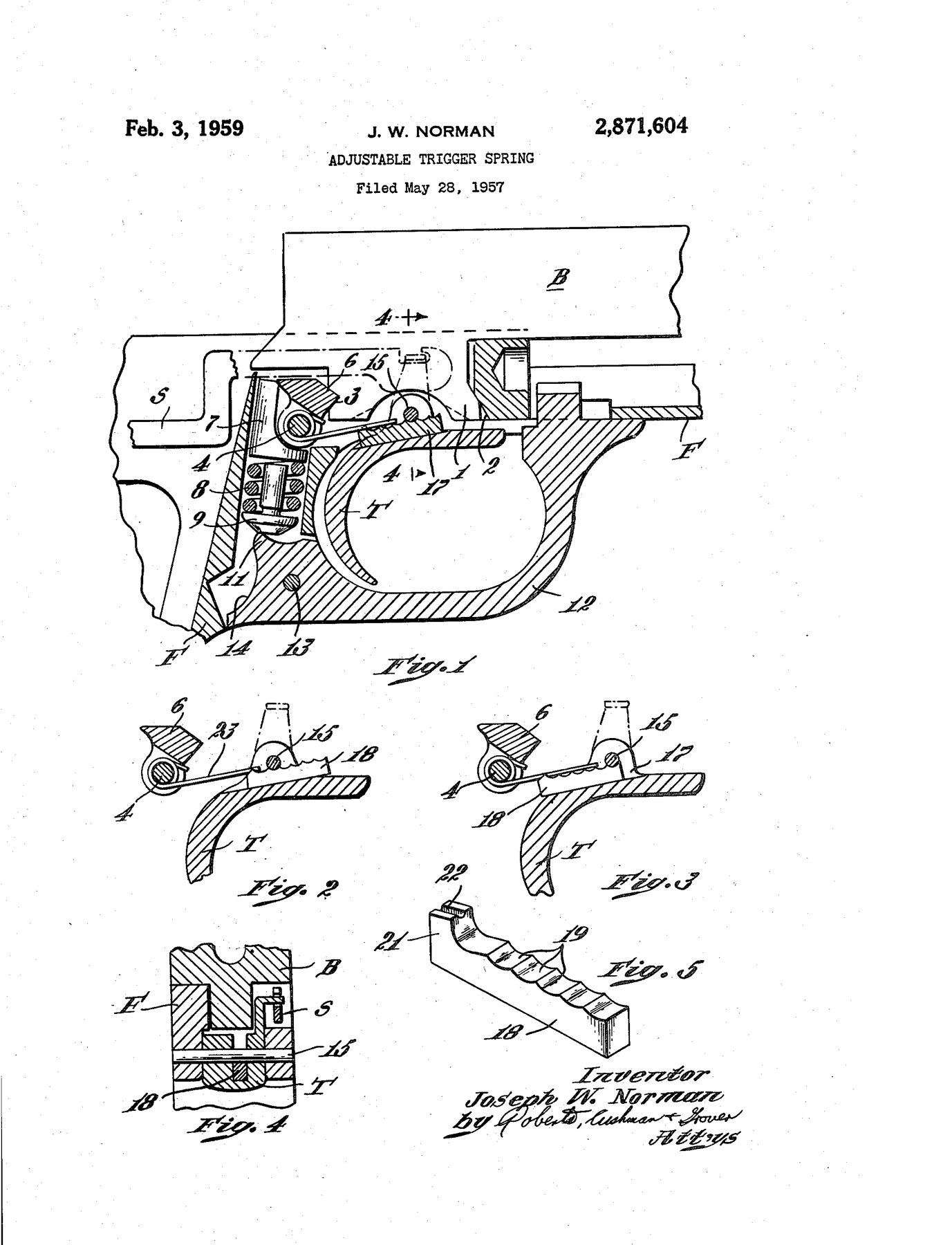
The mechanism is a lever-arm change. A leaf spring anchored in the frame holds the trigger forward “independently of the sear”. Between the spring and the trigger sits a small slide the patent calls a transmitter, lying in a slot along the top of the trigger just under the trigger’s pivot pin. Its upper edge is notched so that the pivot pin locates it in one of several positions. Moving it rearward lengthens the distance from the pivot to the point where the spring bears, so “the spring exerts a strong action on the trigger”; moving it forward shortens that distance and “the effective action of the spring on the trigger is light”. It is shifted “by partially removing the pin”. The patent’s stated object includes that the adjustment “does not change the distance the trigger must be pulled to fire”.7
Whether production Model 41s were built with this transmitter could not be established. It is not mentioned in any of the three editions of the manual examined, in Smith & Wesson’s current product description, or in the Blue Book chronology. It is the kind of detail a Standard Catalog entry or an armourer’s manual would settle, and neither was available. It is presented here as what Smith & Wesson patented for the pistol in 1957, not as a feature of any particular gun. Its adjustment requires drifting the trigger pivot pin, which is precisely the kind of internal work the current manual forbids to the owner.
3.7 The Trigger Stop
The one adjustment the manual gives the owner is the trigger stop, which limits over-travel: how far the trigger continues rearward after the hammer has been released. The 2014 and 2020 manuals give the same procedure, reproduced in Volume 6: with the trigger guard pulled down, a hex wrench in a socket set screw, clockwise to increase trigger travel and counter-clockwise to decrease it, then a dry check that the pistol still fires.1 The manual’s failure test is the important part: “If the gun does not fire, you have turned the trigger stop out too far.”
The reason a bullseye pistol has one is that over-travel is where a shot is disturbed after the sear has broken but before the bullet has left the barrel. A trigger that stops dead just past let-off gives the finger nothing to do in that interval. The manual does not give the wrench size or any recommended setting, and none is supplied here.
3.8 Safety, Slide Stop, Magazine and the Cocking Indicator
Thumb safety. A manual safety lever on the frame: up is safe, down is fire (the manual labels it “manual thumb safety lever”).1 A collector’s compilation reports that from 1994 the safety was changed “to eliminate the ability to lock the slide when on safe”, and that the new safety does not interchange with older guns.8 That is forum-sourced and is not confirmed by the manuals, which do not describe the older safety’s behaviour at all.
Slide stop. After the last round, “the magazine follower exerts upward pressure on the slide stop causing it to engage the slide and to hold it in the ‘open’ position”.1 The slide can be locked back manually by drawing it fully rearward, pressing the slide stop up, and letting the slide come forward slightly onto it. It is released by pressing the slide stop down, which chambers a round if a loaded magazine is in place.
The magazine-seating warning. All three editions of the manual carry the same warning: excessive upward force when seating a loaded magazine “could cause the slide to move forward, chambering a round and making the pistol ready to fire”.1 The manual does not explain the mechanism; the evident one is that the slide stop, holding a spring-loaded slide, is released by the jolt. It is a characteristic of the design stated by the maker, and the reason the manual says to seat the magazine with enough force to lock it, and to check it by pulling on the floorplate, rather than to slap it home.
The magazine. Ten rounds, single column. The 2020 manual shows a load-assist button on the follower, used to pull it down while loading.1 Twelve-round magazines existed from 1992 to 1994 (Volume 2). The manuals of all three editions print a generic warning about “pistols with a magazine safety”, but none says whether the Model 41 has a magazine disconnect; the 2014 edition’s table of contents even lists “Magazine Safety” and “Loaded Chamber Indicator” sections that are not in its body, a template carried over from another model’s manual.1 Whether the Model 41 will fire with the magazine removed is not established by any source consulted, and it should be assumed that it can.
The cocking indicator. Guns made before the 1978 revision have one; later guns do not (Volume 2). No source consulted describes its mechanism, and none is described here.
The firing pin check. The manual tells the owner, when inspecting the pistol with the slide locked open, to confirm that the firing pin is not protruding from the breech face, and if it is, to stop and have the pistol inspected by a qualified gunsmith.1 A firing pin standing proud of the breech face on a blowback pistol is a slam-fire hazard: the slide can fire the round as it chambers it.
3.9 Weights, Brakes and Balance
The 7⅜-inch barrel of 1957 to 1978 was sold with a muzzle brake, and accessory muzzle caps and barrel weights were offered for it; a 1964 Shooter’s Bible, as reported on Wikipedia, shows the barrel grooved to take Olympic-style centre weights (Volume 2).9 The 5½-inch heavy barrel solved the same problem the other way: by putting the weight into the barrel itself. Both are answers to the same requirement, a pistol that hangs steady at arm’s length and returns to the aiming area after each rapid-fire shot, and both say something about what the designers thought a bullseye shooter needed.
No published weight was located for any individual Model 41 barrel, weight or brake, and none is given.
References
Footnotes
-
Smith & Wesson, Safety & Instruction Manual, Model 41 Pistol (© 2020, “Performance Center Models Included”; and the © 2014 edition), and Owner’s Manual, Model 41 (revision code SW41_022504). Copies retrieved 2026-09-19 from https://s3.amazonaws.com/files.ammunitiondepot.com/smith-and-wesson-firearms/pistols/sw-model-41-pistol.pdf, https://www.krale.shop/media/blfa_files/Smith_Wesson_Model_41_manual_EN-min.pdf and http://pdf.textfiles.com/manuals/FIREARMS/s&w_41.pdf. Firing, field stripping (figure 22 in the 2020 edition), inspection, trigger stop and loading sections as quoted. ↩ ↩2 ↩3 ↩4 ↩5 ↩6 ↩7 ↩8 ↩9 ↩10 ↩11 ↩12 ↩13
-
Departments of the Army and the Air Force, TM 9-1005-226-14 / AFM 50-11, 20 July 1959, para. 3b, https://commons.wikimedia.org/wiki/File:TM-9-1005-226-14.pdf. ↩
-
Joseph W. Norman, assignor to Smith and Wesson Inc., “Firearm Barrel Latch”, US Patent 2,887,810, filed 28 May 1957, granted 26 May 1959, https://patents.google.com/patent/US2887810A/en. ↩ ↩2 ↩3
-
Smith & Wesson, “MODEL 41” product page (SKU 130511), https://www.smith-wesson.com/product/model-41, accessed 2026-09-19. ↩
-
“Gun Review: Smith & Wesson Model 41 Pistol”, The Truth About Guns, 12 August 2016, https://www.thetruthaboutguns.com/gun-review-smith-wesson-model-41-pistol/, accessed 2026-09-19. ↩
-
National Rifle Association, NRA Precision Pistol Rules, 2020 edition, rule 3.4, https://competitions.nra.org/media/8365/nra-precision-pistol-rules.pdf. ↩
-
Joseph W. Norman, assignor to Smith and Wesson Inc., “Adjustable Trigger Spring”, US Patent 2,871,604, filed 28 May 1957, granted 3 February 1959, https://patents.google.com/patent/US2871604A/en. ↩ ↩2
-
“Differences in Early Production Model 41 Pistols vs Later Models?”, Smith & Wesson Forum, post by Bastogne71, https://smith-wessonforum.com/threads/differences-in-early-production-model-41-pistols-vs-later-models.722407/, accessed 2026-09-19. No source cited. ↩
-
“Smith & Wesson Model 41”, Wikipedia, https://en.wikipedia.org/wiki/Smith_%26_Wesson_Model_41, accessed 2026-09-19. ↩
Comments (0)