Lewis Gun · Volume 6
Stripping, Cleaning and Keeping It Running
The field strip and detail strip as the Savage handbook and the British manuals give them, the spring balance, the oil quarrel between Utica and Hythe, the magazine, and the parts the manuals told armourers to watch
This volume reproduces the period manuals’ procedures for taking the gun apart for cleaning and putting it back, and their maintenance schedules. It is for the owner of a lawfully registered gun, a deactivated display gun or a museum piece, and for anyone reading a manual. It contains nothing on making, altering or converting a Lewis, and none of the procedures below changes what the gun is. Where the American and British manuals differ, both are given.
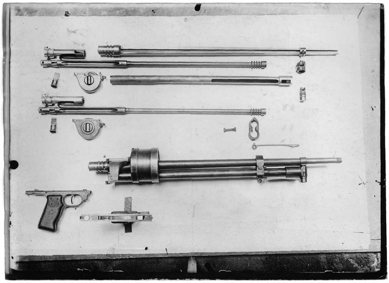
6.1 Before anything: clear it and slack the spring
Two things come first in every manual.
Unload. The Savage handbook’s procedure for clearing without firing: press over the magazine latch and lift the magazine off; hold the charging handle, press the trigger and ease the handle forward “slowly so as to push cartridge from loading ramps into bolt-way”; then pull the handle fully back, raise the safety, and with the point of another cartridge press the round down through the loading slot “so that it can be removed through ejector port”. Then: “After unloading gun always snap (by drawing back charging handle to cock and pulling trigger), to make certain that gun is empty and that there is no cartridge in the receiver.”1 Pridham’s British drill is similar and adds the rule that settles the gun’s state by touch: with a magazine on, a cocking handle fully forward means the gun is safe, and a handle to the rear means it is loaded (Volume 3).2
Release the spring. Savage: “When the gun is not about to be fired the mainspring should not be in tension.” “Simplex” adds the reason for training guns: dry firing with the spring tight “is very apt to wear out the striker, if the tension is high.”13
6.2 Tools
Savage: “To dismount the gun, a cartridge and the barrel mouthpiece spanner (which has a screwdriver end) are sufficient. For detailed stripping, drifts are required.”1 The point of a bullet is the tool named in almost every step of both manuals. The kit that came with the gun, from the Savage handbook’s Plate X: a shell extractor for separated cases, a charging handle extension, the barrel mouthpiece spanner, a barrel cleaning rod, wire cylinder brush and cylinder mop, bristle barrel brush, oil can and a spring balance.1 American Machinist stresses that the Savage gun “may be assembled or stripped without special tools of any kind”.4
6.3 Field strip: the Savage sequence
The Savage handbook, pages 11 to 14, in its own order. Part numbers are Savage’s.1
- Butt stock. “Press and hold in butt latch with point of bullet, give butt stock one-eighth turn to left and withdraw.” (The handbook advises against stripping the butt itself.)
- Release the gear casing. “After removing butt stock hold back trigger, pull back guard far enough to permit rear end of gear casing to swing down until it hangs at such an angle that the receiver locking pin moves freely.” Slide the guard forward against the gear “so as to use guard as handle for receiver in further dismounting.”
- Feed cover. “Press both thumbs against rear end of receiver and pull feed cover rearward with fingers until its lugs clear their retaining surfaces on the receiver. Then lift feed cover off.”
- Feed operating arm. “Swing feed operating arm around magazine post so that retaining lug on magazine post is in line with its cut in hole in feed operating arm. Then lift feed operating arm off magazine post.”
- Charging handle. “Draw back until rear end of rack reaches rear of receiver and pull charging handle out to side.”
- Piston, rack and bolt. “Draw the rack (carrying bolt on striker post) and piston back entirely out of receiver. Lift bolt off striker post.”
- Receiver. “Push receiver locking pin to the rear with point of bullet until it clears its hole in the radiator casing rear locking piece. Turn receiver off barrel (right-handed thread), using guard as handle.”
- Gear casing. “Push receiver locking pin forward out of receiver and unhook gear casing from the gear case hinge pin.”
- Guard. “Hold back trigger and pull guard off to the rear.”
- Ejector. “Pry up rear end of ejector cover with point of bullet and draw out.” Then lift the ejector out with the bullet point in the hub hole.
- Gas regulator cup. Lift the regulator key’s stud clear of its hole with the bullet point; unscrew the cup.
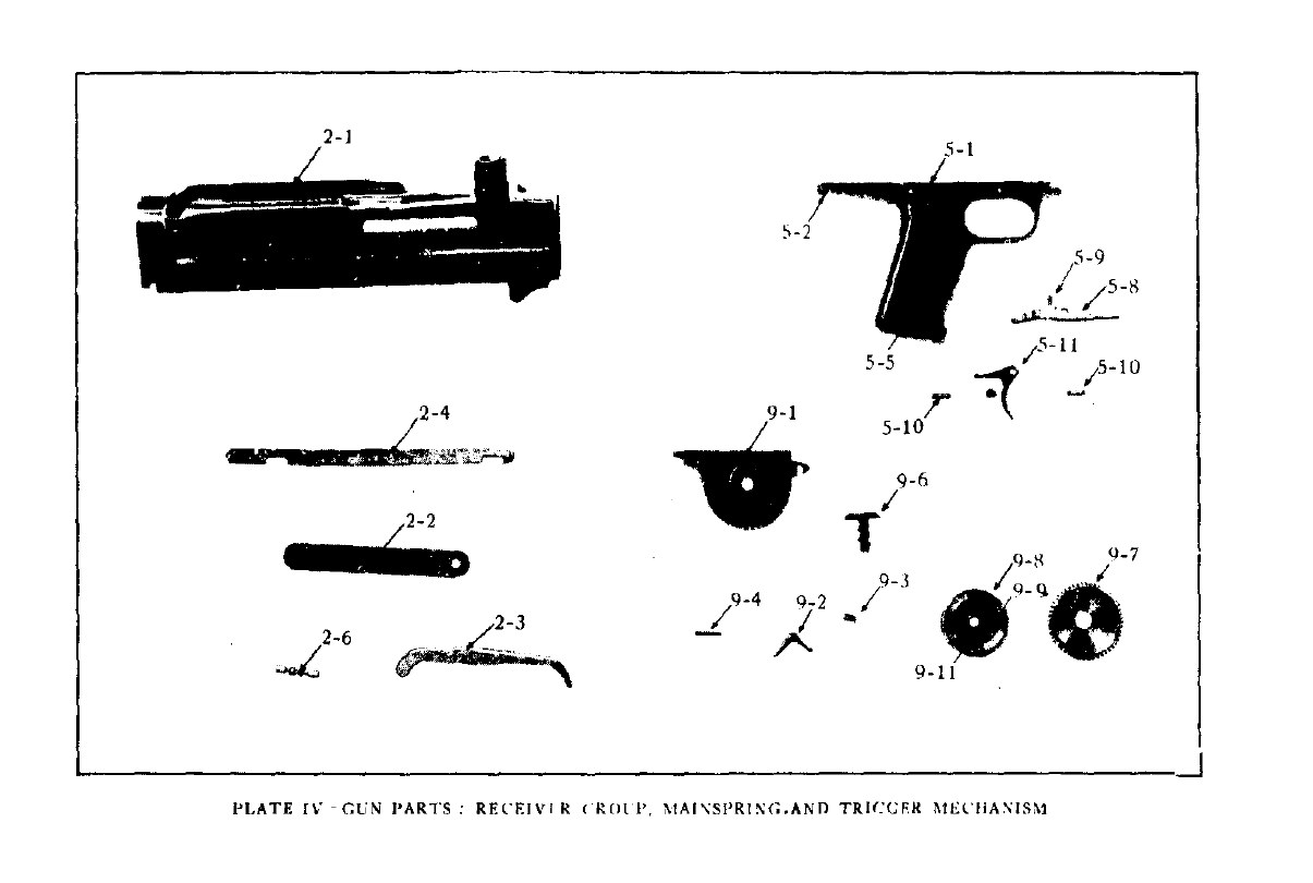
6.4 Field strip: the British sequence
“Simplex” gives the British order, which starts from the same point and differs in detail.3 “It is best that the magazine should be taken off, the chamber cleared, and the cocking handle put in the forward position to start with.”
- Push forward the butt latch with a punch point, twist the butt to the left, and withdraw it.
- “Pull back the trigger and slide back the pistol grip until clear of the body, thus removing the trigger mechanism.”
- “Pull down the pinion casing so that it is clear from the rack. It will usually fall down of its own accord.”
- Slide the body cover rearward until clear of its locking projections.
- Pull the cocking handle back to the rear of its slot and pull it out.
- Remove the feed arm “by forcing back the feed arm latch with a point of a punch”.
- Draw out the piston rod with the bolt on the striker post; take the bolt off.
- Force back the body locking pin and unscrew the body from the barrel.
Pridham adds the British instructor’s warning for anyone clearing a stoppage this way: “take care not to alter the Tension on the Return Spring. Whenever possible, see that C.H. is forward before removing or replacing Pistol Grip”, and gives the correct way to get the bolt out: “Take off Butt—Hold up Pinion with Left Hand—Disengage Pistol Grip—Drop Pinion—Pull out Piston Rod.”2
6.5 Detail strip
The manuals allow further stripping of some groups and discourage it for others.
- Bolt. Savage: “Unscrew and remove feed operating stud. To remove either extractor, lift hook of extractor with point of bullet until stud on shank of extractor is clear of its recess in bolt. Then pull extractor forward out of its slot.”1
- Piston and rack. “To remove striker, drive out striker fixing pin. It is not advisable to separate piston from rack.”1 “Simplex”: the piston head “is fastened by a riveted pin to the piston rod. In case of necessity this can be driven out”.3
- Feed cover. Savage: press the stud of the stop and rebound pawl spring out of its seat with a bullet point through the hole provided, lift the pawls off their studs, and slide the cartridge guide out.1
- Feed arm. “Lift feed pawl spring and feed pawl off their posts, using point of bullet.”1
- Gear casing (spring). Savage: “Press up gear stop with point of bullet and allow mainspring to unwind. Unscrew collet pin and shake out gear.” The spring casing, spring and collet then come out with a bullet point.1 “Simplex”: “Pinion stop should not be stripped”.3
- Guard. “Punch out trigger pin and sear pin. Pull back trigger and lift out trigger and sear.”1 “Simplex” notes that in assembly the axis pins must be driven fully home “otherwise the pistol grip will not slide on to the body.”3
- Ejector. “Simplex”: the cover must go “right home, otherwise it projects and prevents the feed arm finger from going right over to the left, thereby stopping the cocking handle from coming right back.”3
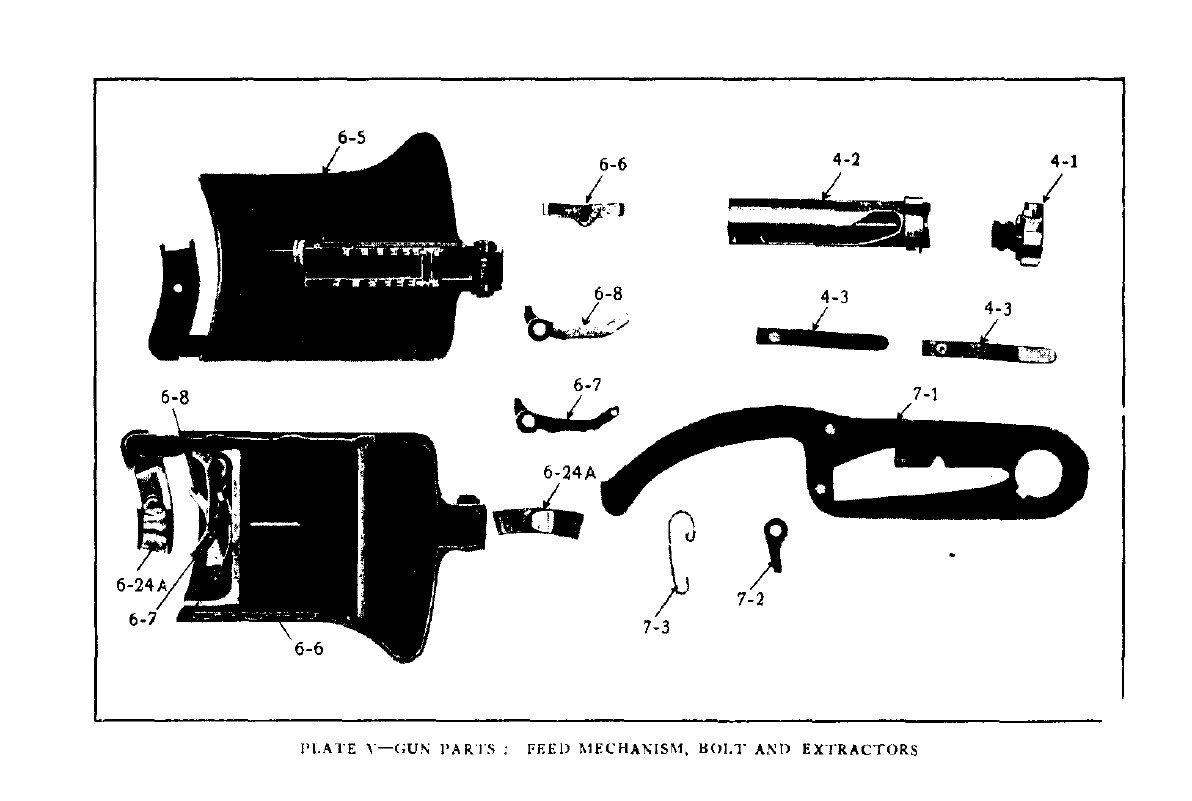
6.6 The barrel group: leave it alone
Both manuals discourage taking the barrel group apart. Savage: “It is not advisable to dismount or strip the barrel group except when necessary. Barrel should not be taken out of radiator except for replacement.”1 “Simplex”, having described how the radiator comes off the barrel: “This should not be done more often than absolutely necessary.”3 The Savage order, for when it is necessary: clamp ring (with the screwdriver end of the spanner), front radiator casing forward, rear radiator casing rearward, gas cylinder (unscrewed “using the piston and rack as a wrench”), gas chamber gland and barrel mouthpiece, both with left-hand threads.1
The gas cylinder carries its own warning, which is a repair point as much as a stripping one: “Push rack well into squared portion of cylinder before unscrewing—if not in far enough, cylinder may be split at rear end”, and if the gun has been left uncleaned “threads may seize and make cylinder hard to unscrew. Thread should then be soaked with oil before trying to unscrew.”1
6.7 Assembly, and the mistakes the manuals warn about
Assembly is the reverse of stripping. Savage gives a twelve-step order for a gun completely dismounted and a list of cautions that are, in effect, the common assembly faults:1
- Avoid damaging “the projections on the rear face of the barrel”, which support the cartridge base and set headspace (Volume 7).
- Keep threads clean, “especially the gas chamber gland, gas cylinder and barrel mouthpiece”.
- Seat the gas chamber correctly: its barrel loop “is tapered, and its smallest diameter must be toward the front”, and the gas port must be “at the bottom and over the center of the gas chamber.” (The RAF notes: the barrel band is stamped “F” for the front.5)
- When replacing the feed cover, the feed arm must be over to the right.
- The feed operating stud must be screwed fully into the bolt, and the cam slot slipped over the striker post, before the piston and bolt go in.
- When replacing the bolt, the feed arm must be over to the left, so the stud enters its groove.
- After inserting bolt, piston and handle, bring the handle fully forward before swinging the gear casing up and engaging the gear with the rack.
- Check the spring tension.
Pridham adds two faults that stop the bolt going in at all: “(1) Tail of Ejector protrudes into Boltway. (2) Rear End of Bolt is not properly screwed up.”2
6.8 Weighing and setting the spring
The return spring is weighed, not guessed. Savage: “To weigh it, engage hook of spring balance (supplied with gun) with charging handle; hold back trigger; draw back charging handle by means of spring balance so that it is just started to the rear. Hold spring balance so as to keep charging handle at this point, and record reading.” The figure: “from twelve to fourteen pounds.”1 “Simplex” has the balance read with the handle held about an inch from the front.3 The RAF gave 11 to 12 pounds for aircraft guns.5
The adjustment works by letting the rack ratchet past the gear with the gear casing dropped. Savage: to increase tension, hold the gear casing up so the gear engages the rack and draw back the charging handle; drop the casing so the gear disengages, and push the handle forward; then raise the casing and lock it with the guard. To decrease, the reverse.1 Pridham gives the scale: drawing the handle back “1 inch gives 2 to 3 lbs.” and cautions that the pinion must be held up firmly while the handle is drawn back, “or damage may be done to the Teeth of Rack or Pinion”.2
6.9 Cleaning
The bore. Savage directs cleaning from the muzzle, “so as to reduce as far as possible the danger of injuring” the guide lips at the rear of the barrel, with the same solutions as for the US Model 1906 rifle, and the bore swabbed “as soon as gun is unloaded”. For metal fouling it gives an ammonia procedure that requires the barrel off the receiver and the gas port corked. Corrosive priming was the norm, and both manuals assume it: Savage, “Cleaning the barrel should be repeated every day for several days after the gun has been fired”; Pridham, “Clean Barrel thoroughly daily for at least ten days, leaving Oily”, with “Boiling Water, if available”.12
The gas parts. Savage: withdraw bolt and piston, put the cylinder rod through the piston hole in the receiver, “Clean first with a wire brush and gasoline and then with the mop and oil.”1 The British manuals used paraffin for the gas parts; see the next section.
The action. Savage: “Soak off hard fouling with gasoline or oil. Parts cleaned with gasoline should be dried and oiled afterward.” Pridham’s schedule: clean “daily in damp climates; weekly in dry atmospheres”, and in gassed areas “clean thoroughly with Petrol or Paraffin. Burn all rags used.”12
6.10 Oil: where the manuals disagree
The American and British manuals give opposite advice on oil in the gas system.
Table 1 — Oil: where the manuals disagree
| Savage handbook (US, c. 1918) | “Simplex” (British, 1917) | Pridham (British, 1940) | |
|---|---|---|---|
| gas cylinder | ”Clean first with a wire brush and gasoline and then with the mop and oil." | "Never put oil in cylinder or on piston head cup.” Clean cylinder and piston cup “with paraffin”. | ”Remove oil from Bore and Gas Cylinder (if oily). All gas parts to be absolutely dry.” “Oil in Gas Cylinder causes Fouling, and renders Gun very liable to Frictional Stoppages.” |
| action | ”The striker post and the inside of the bolt should always be kept well oiled … Be liberal in use of oil.” | oil bolt and piston way, rack and pinion teeth, striker post, cam slot, feed parts | ”Never put too much Oil on the Frictional Parts, as they work better with a little, especially in cold weather.” Bolt and striker post smeared “with graphite grease”. |
| over-oiling | — | “If the gun is overoiled it will smoke; this may disclose its position.” | — |
Sources: Savage pp. 51–53;1 “Simplex” chs. VII and X;3 Pridham secs. IX and X.2
The two British manuals agree with each other and are later in date. The Savage handbook was written for a factory-fresh gun and the American service rifle’s cleaning routine. A reader following either should follow the British rule for the gas parts, dry, and the British caution on the action, a little oil, because both are framed around stoppages the Savage handbook does not address. That is this dive’s reading of the conflict, not a statement in any source.
6.11 Before, during and after firing
The three manuals’ checklists overlap. Combined, with the source for each item:
Before firing. Bore clear (Savage). Weigh and set the spring (all three). Oil as above (all three). Test the feed: put an empty magazine on and work the handle “to prove that feed mechanism rotates magazine” (Savage). Tap the top of the feed arm finger “to see it is not bent”; check the pinion pawl axis pin and that the ejector cover is down (“Simplex”). Barrel mouthpiece and clamp ring tight (Pridham, “Simplex”). Small gas hole to the rear (“Simplex”). Examine magazines and ammunition; spares and oil to hand (all).132
During a pause. Replace a partly emptied magazine with a full one (Savage, “Simplex”). Raise the safety; if time allows, unload and oil the bolt, striker post and piston; reweigh the spring; “Do not allow tension to drop under twelve pounds, as it might cause breakage of parts” (Savage). “Turn Gas Regulator slightly to prevent ‘seizing’ of threads”; check the clamp ring (Pridham). “If gun misfires, wait a few seconds before drawing back charging handle” (Savage).12
After firing. Unload and snap; release the spring; clean and oil the barrel; clean the gas parts; collect unfired rounds from among the empties (Savage). Strip, clean and oil fully when back in billets; examine, dry and oil magazines; record rounds fired, breakages and the number of the barrel in the gun’s history sheet (Pridham).12
6.12 The magazine
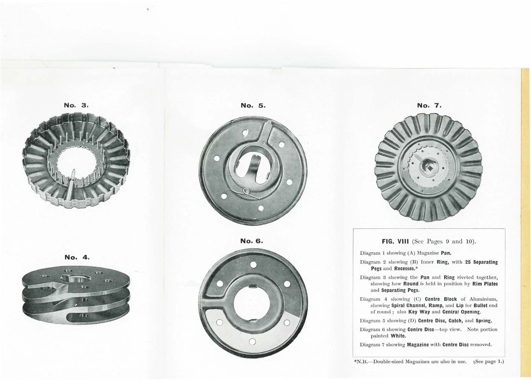
The magazine needs as much care as the gun. Savage’s loading instruction carries its own inspection: insert the loading handle, then “Spin magazine on loading handle to see that it is not distorted”, place cartridges between the separator pins, and “Do not leave an empty space between cartridges, as in firing this would cause a stoppage.” When full, “turn magazine center back until it snaps. This locks magazine.” The loading tool, clamped to a table, strips cartridges from clips into a chute while the magazine is turned clockwise beneath it; “If a space in magazine is skipped, rotate magazine backward past vacant space and then rotate forward again.”1
Handling: “Deformation of the rim of the magazine or the entry of dirt or grit in the bullet groove in the magazine center should be carefully guarded against.”1 The 1916 General Staff pamphlet is blunter: a full magazine dropped on hard ground “will probably be so dented that it will not fit the gun.”6 Oil: Savage lightly oils the magazine latch and the outer edge of the spacer ring.1 Chinn records that the American service developed “a simple set of magazine rim and spacer pin gages for use in the field”, which is a measure of how much the feed depended on those two dimensions.7
6.13 Inspection and parts that wear
The Savage handbook’s “Care and Adjustment” section is an inspection schedule, and its first rule is about who does what: “Adjustment by use of file, oil-stone or emery should be made only by an armorer.”1 Its checks:1
- Barrel: bore, chamber, “the guide lips of the chamber, which project from the rear face of the barrel, and the thread on the muzzle.”
- Gear, casing and mainspring: teeth, stop and spring undamaged, hinge pin secure, spring not broken.
- Feed arm and feed cover: pawls and springs undamaged and adjusted; cartridge guide properly assembled.
- Piston: connecting pin tight; rack teeth and cocking notch undamaged; striker post’s working faces not burred; striker undamaged.
- Bolt: “The edges of the cam slot should be smooth.” Headspace: “Test head space with maximum heading gauge. A bolt which closes over the maximum heading gauge must be changed.”
- Extractors: “Weigh each extractor by engaging hook of spring balance with extractor hook and pulling at right angles to bolt. Read balance when extractor moves. If under three pounds, exchange extractor.”
The handbook’s “Notice to Armorers” singles out one wear surface: “The efficient working of the Lewis machine gun largely depends upon the bearing surfaces between the sides of the striker post and the sides of the cam-shaped slot in the bolt being kept perfectly smooth.” Burring occurs “generally on the right-hand side” of the post and “generally on the left-hand side” of the slot, and is to be removed with “a very fine oil-stone or very fine emery cloth”; “If either too coarse materials or too much careless force is used to smooth these surfaces, the angle of sliding contact may become slightly altered and more roughness or ‘burring’ may be caused.”1 Volume 7 explains why that angle matters.
Two more wear items appear in the British notes. On speeded-up aircraft guns, “The length of the Volute Spring should be carefully checked after each flight and it should be replaced when its length has decreased to 1”.”5 And the Textbook of Small Arms records that a new barrel can change the gun’s headspace, because “the condition of the projection on the rear face of the barrel is a determining factor”.8 No manual consulted gives replacement intervals in rounds for any part.
6.14 Storage
Savage’s list for a gun going into its box: “1. Bore oily. 2. Exterior and working parts oily. 3. Nothing in bore. 4. Sight down. 5. Spare parts in box. 6. Cleaning material and oil in box. 7. Mainspring released. 8. Charging handle forward and safety up.”1 Item 7 is the one that matters most to a collector: a clock spring left wound for years takes a set.
6.15 What could not be established
- Replacement intervals for barrels, springs, extractors or pawls, in rounds or time: none in any manual consulted.
- The current availability of spare parts, which is a market matter covered in Volume 8 only as far as the law goes.
- The Ordnance Department’s 1917 handbook, which may give US Army procedures that differ from Savage’s.
References
Footnotes
-
Savage Arms Corporation, Hand-Book of the Lewis Machine Gun, Model 1918, Caliber .30 (Utica, N.Y., c. 1918), pp. 11–53, Plates IV, V and X. https://www.forgottenweapons.com/wp-content/uploads/Lewis/lewismanual.pdf, consulted 2026-10-19. ↩ ↩2 ↩3 ↩4 ↩5 ↩6 ↩7 ↩8 ↩9 ↩10 ↩11 ↩12 ↩13 ↩14 ↩15 ↩16 ↩17 ↩18 ↩19 ↩20 ↩21 ↩22 ↩23 ↩24 ↩25 ↩26 ↩27 ↩28 ↩29 ↩30 ↩31
-
Major C. H. B. Pridham, Lewis Gun Mechanism Made Easy, 6th edition (Gale & Polden, 1940), sections III, VIII to X and Fig. VIII. https://www.forgottenweapons.com/wp-content/uploads/Lewis/Lewis%20Gun%20Mechanism%20Made%20Easy.pdf, consulted 2026-10-19. ↩ ↩2 ↩3 ↩4 ↩5 ↩6 ↩7 ↩8 ↩9 ↩10
-
“Simplex”, Instruction on the Lewis Automatic Machine Gun, 3rd edition (Forster Groom, 1917), chapters IV to VII and X. https://archive.org/details/instructionlewisautomaticmachinegun1917, consulted 2026-10-19. ↩ ↩2 ↩3 ↩4 ↩5 ↩6 ↩7 ↩8 ↩9 ↩10
-
“The Manufacture of the Lewis Machine Gun”, American Machinist, 6 December 1917. https://archive.org/details/Ame-mach-lewis-gun, consulted 2026-10-19. ↩
-
Royal Air Force, Instructional Notes on the Lewis Gun (April 1918), sections II, VI and X. https://archive.org/details/raflewisgun, consulted 2026-10-19. ↩ ↩2 ↩3
-
General Staff, Some Notes on Lewis Guns and Machine Guns, S.S. 122 (September 1916). https://archive.org/details/1916-uk-ss-122, consulted 2026-10-19. ↩
-
George M. Chinn, The Machine Gun, vol. I, Part IV, chapter 1 (Bureau of Ordnance, 1951). https://www.ibiblio.org/hyperwar/USN/ref/MG/I/MG-4.html, consulted 2026-10-19. ↩
-
War Office, Textbook of Small Arms 1929 (HMSO), cartridge head space. https://archive.org/details/textbooksmallarms1929, consulted 2026-10-19. ↩
Comments (0)