Lewis Gun · Volume 3
How It Works: Rack, Clock Spring, Striker Post and Pan
The Lewis cycle part by part from the Savage handbook and the British manuals: gas, a spring kept out of the heat, a bolt that cannot fire until it has locked, a magazine the gun turns itself, and a radiator driven by the muzzle blast
3.1 The gun in one paragraph
The Savage Arms Corporation’s handbook puts it in one line: “The Lewis Machine Gun is magazine-fed, gas-operated and air-cooled.”1 Gas tapped near the muzzle drives a long piston rearward. A rack cut in the underside of the piston rod turns a pinion, winding a flat clock spring in a drum below the receiver. A post on the rear of the piston rod rides in a curved slot in the bolt, so that the piston’s travel first withdraws the striker, then turns the bolt to unlock it, then carries it back. On the way back, a stud on the bolt swings a feed arm across the top of the receiver, which turns the pan magazine one step and drops the next cartridge onto the feed way. At the end of the stroke the sear catches the rack and holds everything open. Pressing the trigger releases the rack; the spring unwinds, and the post drives the bolt forward, turns it into its locking recesses and then, and only then, carries the striker to the primer.
This volume walks through that cycle part by part, with the manuals’ own words. Strip and maintenance are in Volume 6; stoppages in Volume 7.
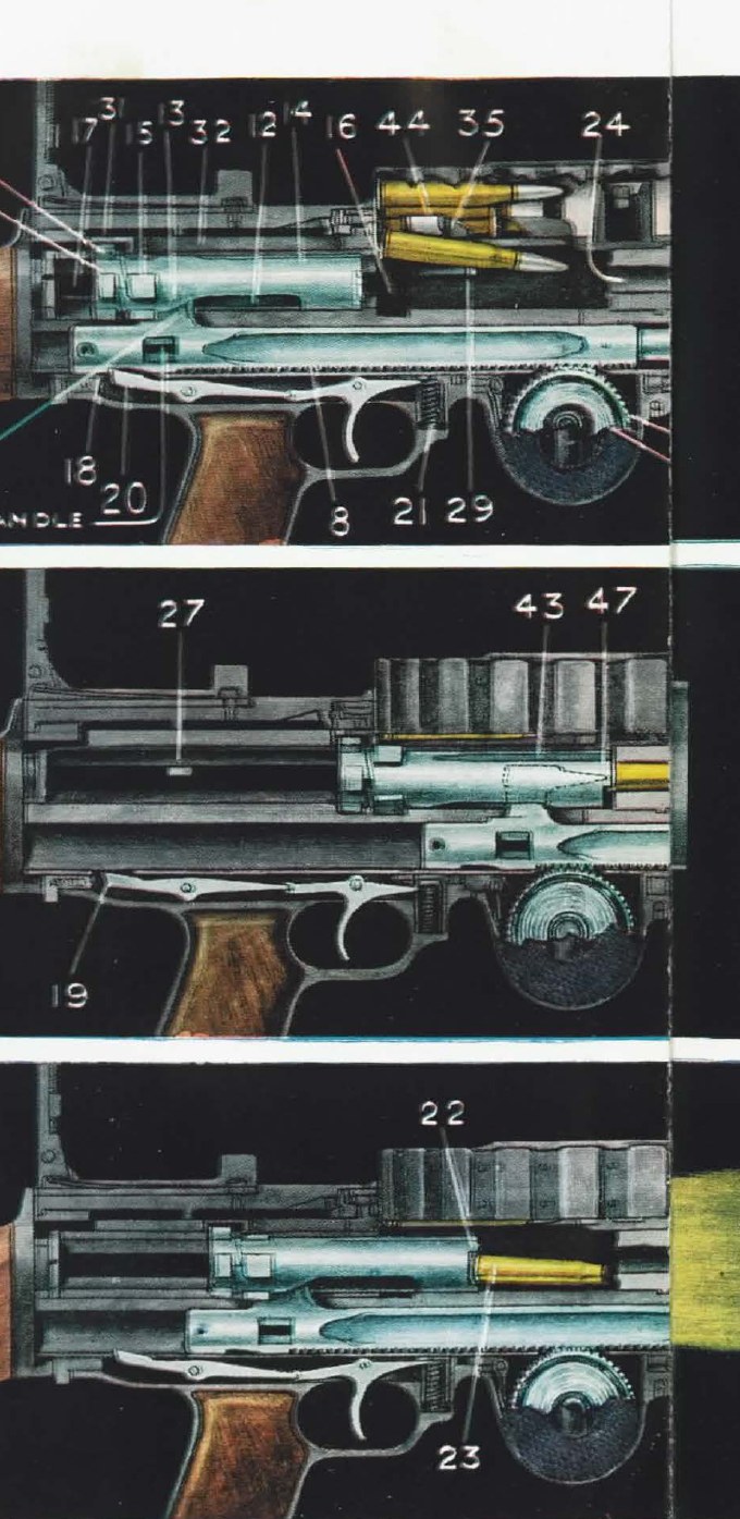
Pridham’s key to the plate, for the numbers visible in it: 8 teeth on the rack; 11 striker post; 12 cam slot; 13 curved portion of the cam slot; 14 bolt; 15 locking lugs; 16 locking recesses; 17 guide grooves; 18 bent; 19 nose of the sear; 20 sear; 21 trigger spring; 22 extractors; 23 empty case; 24 chamber; 26 rear end of the bolt; 27 tail of the ejector; 29 head of the ejector; 30 feed arm actuating stud; 31 grooved tail of the feed arm; 32 feed arm; 35 projecting tongue of the body cover; 43 top extractor; 44 cartridge guide; 47 striker.2
3.2 Names: British and American
The British and American manuals describe the same parts in different words, and the difference matters when reading either.
Table 1 — Names: British and American
| Part | British (Pridham 1940; RAF 1918) | American (Savage handbook) |
|---|---|---|
| receiver | body | receiver |
| top cover carrying the pawls | body cover | feed cover |
| piston and rack | piston rod | piston and rack |
| spring that drives the action forward | return spring | mainspring |
| gear that winds it | pinion (in the pinion casing) | gear (in the gear casing) |
| catch on the rack | bent | cocking notch |
| trigger housing and grip | pistol grip, trigger group | guard |
| handle | cocking handle | charging handle |
| left pawl in the cover | No. 1 (left) stop pawl | rebound pawl |
| right pawl in the cover | No. 2 (right) stop pawl | stop pawl |
| tool for a separated case | clearing plug | shell extractor |
| stud on the bolt that works the arm | feed arm actuating stud | feed operating stud |
Sources: Pridham,2 RAF Instructional Notes,3 Savage handbook.1
3.3 The figures, by source
The manuals give different figures for weight, length and velocity, because they describe different guns and cartridges. They are given separately, not averaged.
Table 2 — The figures, by source
| Figure | Savage handbook, Model 1918, .30-06 | Pridham 1940, .303 | RAF 1918 | Textbook of Small Arms 1929, .303 |
|---|---|---|---|---|
| weight of gun | 26 lb 8 oz | ”26 to 28 lbs.” | ground (Mk I) 26 lb; aerial (Mk II) 17 lb | 26 lb |
| bipod / mounting | 1 lb 12 oz (gun with bipod 28 lb 4 oz) | 2¾ lb | — | — |
| length | 51 in with rifle butt; 44 in with spade grip | 50½ in | — | — |
| barrel | 26⅝ in | 26¼ in | — | 26¼ in |
| rifling | 4 grooves, one turn in 10 in | — | 4 grooves, right hand | — |
| velocity | 2,700 ft/s (150-gr bullet) | 2,440 ft/s | — | — |
| magazine | 47 rounds; 1 lb 8 oz empty, 4 lb 8 oz filled | 47 rounds; 1½ lb empty | single 47 (1½ lb empty, 4¼ lb full); double 97 (3¾ lb empty, 8 lb 14 oz full) | — |
| rate | — | “an average rate of ten rounds per second” | — | — |
| trigger pull | 12 to 14 lb | — | — | — |
| spring tension | 12 to 14 lb | 12 to 14 lb, handle forward | 11 to 12 lb (aircraft) | — |
Sources: Savage handbook p. 9 (checked against the page image),1 Pridham p. 1 and footnote,2 RAF Instructional Notes pp. 2 and 9 (checked against the page image),3 Textbook of Small Arms 1929, table of light machine guns.4
The parts count is a matter of definition. “Simplex” (1917) says the parts “do not number more than sixty-two”; American Machinist, describing Savage production, says “some 60 parts” in one article and “the 62 parts all told, of the gun proper” in another, and adds that “only 1 screw and 4 pins are used in its make-up”.56
3.4 Gas: port, chamber, regulator, cylinder
The gas is taken near the muzzle, not near the chamber. The RAF’s 1918 notes: “A Gas Vent is bored in the barrel 4” from the muzzle to allow the gas to pass into the gas chamber. Around this vent, in the thickness of the barrel, is a conical recess with a flat base.”3 A stud on top of the barrel near the breech fits a slot in the radiator, “ensuring that the gas vent is in position to receive the gas chamber”; the barrel attaches to the body by a square thread.3
From the vent the gas passes through the gas chamber and the gas regulator, a plug with holes of different sizes, into the gas cylinder under the barrel, where it strikes the head of the piston. “Simplex” describes “a cup-faced piston”.5 The regulator is the gun’s only adjustment of gas, and the two patterns differ:
- British .303: two holes, marked L and S on the exposed end. “Under ordinary circumstances the small hole of the gas regulator should be used.” If, after long firing, the gun “begins to fire slower than usual”, the regulator is to be taken out and cleaned, a single shot fired to clear the port, and firing resumed “with the large hole of the gas regulator turned towards the rear”.35
- American .30: Pridham notes that “Gas Chamber of .300 Gun has also a Gas Chamber Gland. Gas Regulator has 4 holes (Nos. 1, 2, 3, 4) varying in size. .303 Gun has 2 holes only. Smallest hole that gives sufficient gas should be used.”2
Chinn’s account of the American programme gives the gas orifice of the standard gun as .130 inch, tried at .190 (too violent) and .150 (with a muzzle booster) during the 1918 attempt to raise the rate of fire; see Volume 2.7
3.5 The rack, the pinion and the clock spring
The spring is the gun’s signature and the reason the underside of a Lewis has a round hump ahead of the trigger. Lewis’s patent gives the reason it is there: a mainspring wrapped round the piston rod inside the gas cylinder sits “directly in the heated zone and quickly deteriorates from the effect of the heat”, so he moved it to “a small convolute spring located to the rear of the gun barrel entirely out of the heated zone”, shaped “to give practically a constant pull throughout each action”.8
The parts, from the RAF notes: the pinion casing hooks to the body at its front and holds the pinion and spring; the pinion “is a hollow casing which forms one half of a drum … On its outer circumference are 52 teeth”; inside it the spring casing contains “the Return Spring, which is flat and coiled”, anchored at its outer end and hooked at its inner end to a hub on the tension screw. A pinion pawl holds the spring wound when the trigger group is off the gun, and is lifted clear when the group is in place.3
The piston rod’s teeth mesh with the pinion. Savage: “Drawing the rack teeth back over the gear teeth with which they are meshed rotates the gear and winds the mainspring during the entire opening movement.”1
The tension matters, and both manuals say so in nearly the same words. Savage: the tension must be “from twelve to fourteen pounds. If the tension is too low the rack will strike the butt tang too hard in opening and the action may fail to close or the gun may misfire. If it is too high the gun will fire too fast; if much too high the gun will not open far enough to feed the next cartridge.”1 “Simplex” records that “Messrs. Lewis, Ltd., state that 12-14 lb. is the correct tension”, that “If the tension is correct, the bolt and rod barely touch the tang”, and that he found the gun fired well at a lower tension on the small gas hole.5 The RAF’s 1918 notes give a lower figure for the aircraft gun: “11 to 12 lbs.”3 How the tension is measured and changed is in Volume 6.
The clock spring is also the reason the gun should not be stored cocked or tensioned. Savage: “When the gun is not about to be fired the mainspring should not be in tension.”1
3.6 The bolt, the striker post and the cam slot
The bolt is a cylinder with locking lugs at its rear and a slot cut through it. The Australian War Memorial’s catalogue description is precise: “The operating action uses a rotating bolt which has four radial locking lugs located at the rear which lock into recesses in the receiver walls. The bolt is operated by a vertical stud which enters a helical cut made in the bolt body. The stud is located on the gas piston rod … The firing pin is fixed to a vertical stud located on the gas piston rod.”9
The slot has two parts: a curved (helical) portion at the rear and a straight portion ahead of it. The striker post rises from the piston rod into it and carries the striker on its front face. The body’s bolt-way has “four Cruciform Guide-ways, or grooves in the form of a cross, which admit the lugs on the bolt and on the feed arm actuating stud. At the forward end of the bolt-way are the Locking Recesses”.3
The War Office’s Textbook of Small Arms 1929 chose the Lewis as its example of locking by rotating lugs (its figure reference numerals are omitted here):
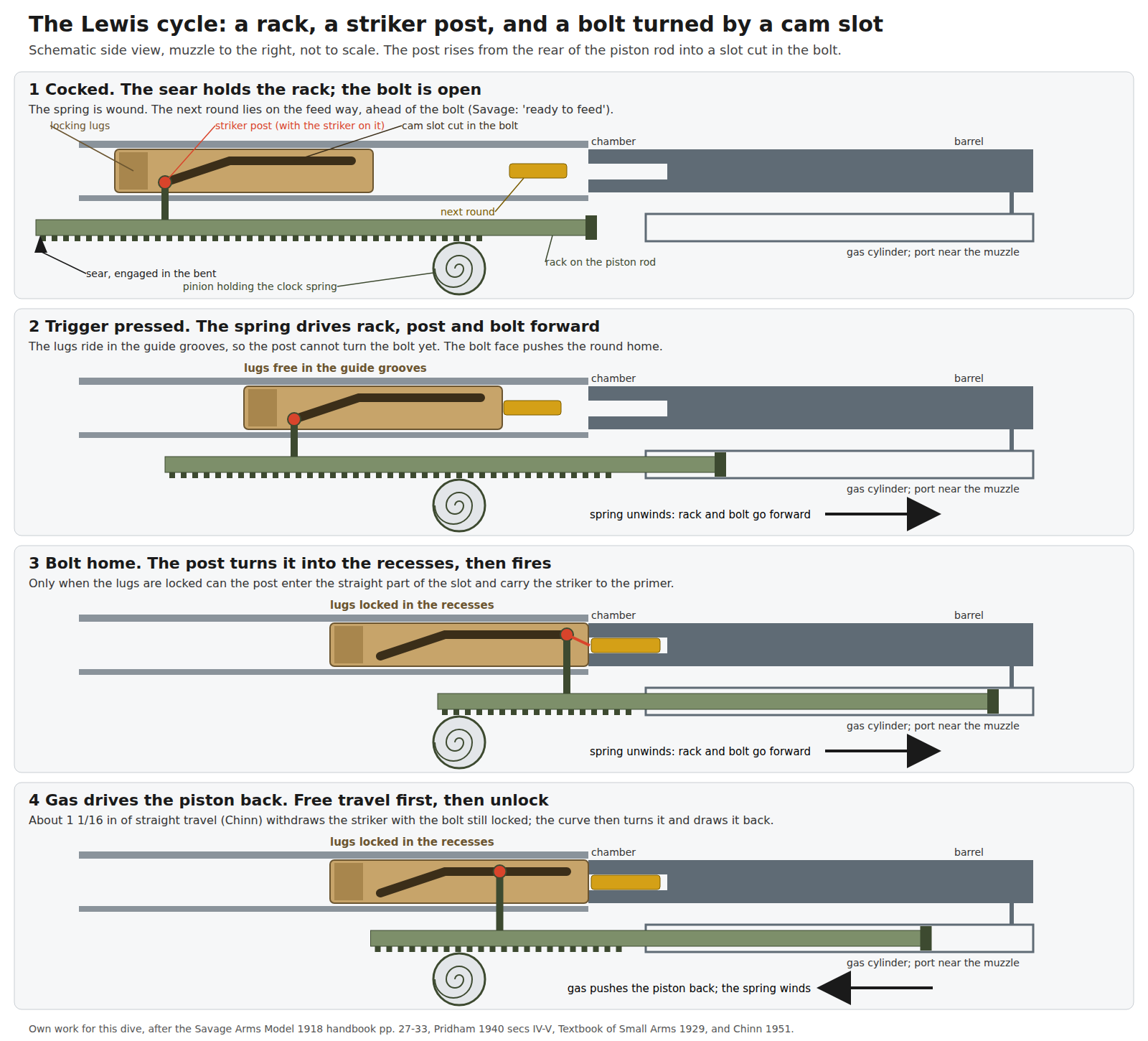
“In the Lewis, which may be taken as typical of this design, the striker is carried on a post mounted on the rear end of the piston, and this post moves backwards and forwards in a slot in the bolt. When the piston commences to travel forwards under the action of the return spring the striker post is lodged in the recess at the rear of the slot in the bolt, and its left side bears against the left side of the curved portion of the slot. The locking lugs on the bolt, being engaged with the guide grooves of the body prevent it turning, and it is therefore carried forward until such time as the locking lugs are opposite the locking recesses. The striker post then travelling along the curved portion of the slot causes the bolt to turn, thus locking it to the body, and continuing along the straight portion of the slot carries the striker forward to fire the round.”4
Two consequences follow from that geometry, and both are stated in the sources:
- The gun cannot fire unlocked. The striker can only reach the primer once the post has passed through the curve, and the post can only pass through the curve once the lugs are in front of their recesses. The Textbook lists the Lewis as the type in which firing is timed “by attaching the striker to some member of the moving parts, the completion of whose forward movement is suitably timed”.4
- The bolt stays locked while pressure falls. Pridham calls the straight portion of the slot a “SAFETY LOCKING DEVICE … a device to insure Locking of the Bolt until the Bullet is clear of the Muzzle.”2 Chinn gives the length of that straight free travel on production guns as 1.0625 inches, against 0.875 inch on the prototypes that failed in 1913 (Volume 1).7
3.7 The cycle, step by step
The Savage handbook combines “instructions as to manual operation and description of the corresponding mechanical functioning” so as “to associate the effect with the cause”, and its account is followed here.1
Cocking by hand. With a magazine on the post, drawing the charging handle fully back “draws back the piston and rack and performs by hand what the gas pressure of firing does”. In the first part of the travel “the striker post moves back through the longitudinal part of its cut in the bolt and merely draws back the point of the striker from the face of the bolt. The bolt itself remains in its locked position and does not move.” In the next part the post “strikes with its right side the cam surface in the right side of its slot in the bolt and causes the bolt to rotate from right to left, turning the locking lugs out of their recesses”. Then the post reaches the rear of its cut “and in its further travel carries the bolt directly back with it.”1
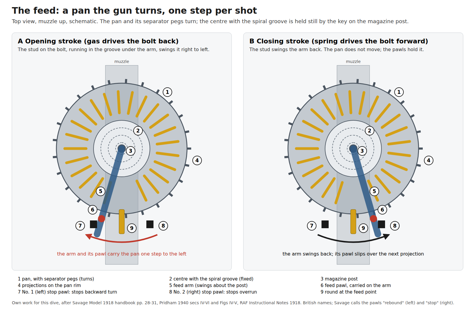
Feeding on the rearward stroke. “The top lug of the feed operating stud, traveling in the groove in the under side of the feed operating arm, cams the feed operating arm so that it swings across the top of the receiver from right to left.” Its pawl turns the pan, a cartridge drops into the arm’s opening and comes under the cartridge guide; the stop pawl then prevents further rotation. When the bolt reaches the rear end of the ejector “it drives it into its slot, thus pivoting the ejector head out”. The rack’s cocking notch rides over the sear, and the rear of the rack strikes the butt tang.1
Held open. “The mainspring now rotates the gear, whose teeth, meshed with those of the rack, drive the rack forward a trifle till the nose of the sear engages with the cocking notch in the lower edge of the rack and suspends the operation. The gun is now ready to fire.”1 This is an open-bolt gun: the chamber is empty and the bolt to the rear while it waits.
Firing. Pressing the trigger draws the sear down. “The rack is driven forward by the pressure of the mainspring”. The post “now simply drives the bolt forward without rotating it because the bolt is prevented from rotation by the cruciform shape of the bolt-way in the receiver at this point.” The feed arm swings back to the right; “The feed pawl slips over the projection on the rim of the magazine and engages behind it.” The bolt face strikes the base of the cartridge “held ready for it in the loading ramps of the receiver, and it drives the cartridge before it into the chamber. The extractors spring over the rim as soon as the cartridge seats.” The lugs reach their recesses; the post “cam[s] the bolt around to the right”, locking it; and “As the bolt locking is completed the striker post enters the longitudinal front part of its cut, carries the striker against the primer of the cartridge in the chamber, and fires the cartridge.”1
The gas stroke. “When the bullet passes the gas port near the muzzle of the barrel, gas under high pressure is driven through the gas port into the gas chamber and through the hole in the gas regulator cup onto the head of the piston.” The rearward stroke then repeats the hand-cocking sequence, with extraction and ejection added.1
Continuing. “If the trigger is still held back, and the sear consequently depressed, at the beginning of the closing stroke of the action the gun will continue firing. If the trigger has been released so that the sear intercepts the cocking notch in the rack, the gun is left ‘ready to feed.‘“1
3.8 Extraction and ejection
Two extractors on the bolt grip the rim. The RAF notes explain why the extractors can grip it at all: “On the rear face of the barrel is a projection which coincides with the cut-away portion of the bolt face when the breech is closed. By this means the rim of the cartridge is held away from the barrel, so that the extractors are able to grip it, while at the same time the base of the cartridge is efficiently supported.”3 That projection is also a headspace-critical surface; the Textbook warns that “the condition of the projection on the rear face of the barrel is a determining factor” in the Lewis’s headspace (Volume 7).4
The ejector is a pivoted, hook-shaped lever in a seating on the left of the body, under a sprung cover. It is “slightly cranked, in order that, while keeping its head in line with the slot in the face of the bolt, its tail may be in position to be actuated by the lug on the bolt.”3 Going forward, the bolt knocks the head out of the boltway and swings the tail in behind it; coming back, the bolt’s left lug strikes the tail, the head “swings in and ejects the Empty Case through the Ejection Slot” on the right.2 Savage: the ejector head “swings sharply against the left side of the extracted shell, throws the shell out of the ejector port.”1
3.9 The pan magazine
The magazine is a flat drum carried horizontally on a post on top of the body. Savage: “a circular drum in which the cartridges are arranged radially, bullet ends toward the center. The magazine center has a deep spiral groove in which the bullet ends of the cartridges engage and by which they are controlled. The other parts of the magazine are rotated around the center during the operation of the gun, thus driving the spirally arranged column of cartridges down the helical groove of the magazine center until they are successively reached by the feed operating arm.”1
Pridham gives the construction: a circular rotating pan and an inner ring carrying the separating pegs, riveted together, which turn around a stationary centre block of aluminium and a centre disc with the catch and spring. Off the gun, the nib of the catch engages “one of the twenty-five recesses of the Inner Ring” and locks the pan. On the gun, “Magazine Catch is forced to the Right by the Hollow Cone of the Magazine Post; this disengages the Nib”, and the centre is held still “by the Key on the exterior of the Magazine Post, which fits into the Keyway on the Centre Block.”2 American Machinist describes how Savage made them: the corrugated steel shell drawn in a die, rivet holes punched by radially operating tools, and the aluminium centre milled with its spiral groove on multiple-spindle machines.6
“Simplex” explains the corrugations: “The walls of these magazines are corrugated, partly for strength and also to enable the magazine to be rotated mechanically”, and the stop pawls catch against them.5 The Savage handbook makes the claim the design rests on: “In the Lewis Machine Gun cartridges are under mechanical control at all times and feed is absolutely positive. The gun will function perfectly at any angle of elevation or depression and when turned on either side or upside down.”1 That is the maker’s claim; the manuals’ own stoppage tables show that the magazine was also the gun’s most common source of trouble, mostly when dented (Volume 7).
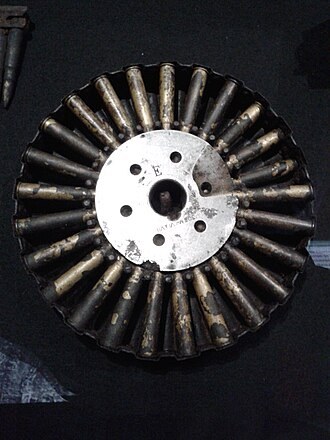
Capacity. The ground magazine is 47 rounds in every source. The large aircraft magazine is not quoted consistently:
Table 3 — Capacity. The ground magazine is 47 rounds in every source. The large aircraft magazine is not quoted consistently
| Capacity | Source |
|---|---|
| 97 | RAF Instructional Notes, April 19183 |
| 97 | American Machinist, 1917–18, Savage aircraft model6 |
| 96 | Chinn 1951, in the text (his photograph caption says 97)7 |
| “about 94” | Pridham 1940, “double-sized … in use by the Royal Navy and the R.A.F.”2 |
The two 1918 primary sources say 97, and 97 is the figure used in this dive. Truby also illustrates an experimental Savage drum of 146 rounds.10
3.10 The feed arm and the pawls
The feed arm pivots on the magazine post and lies across the top of the body under the pan. Its tail carries a groove on the underside in which the feed arm actuating stud, screwed into the bolt, runs. Its body carries the feed pawl. The body cover above it carries the two stop pawls in a housing behind the tongue, with a flat spring pushing their free ends forward.3
Pridham’s sequence, with the gun’s left and right:2
- Backward movement. The stud “carries the Feed Arm across to the Left”. The feed arm pawl, engaged behind a projection on the magazine, “rotates the Magazine one space to the Left”. A round, forced down the slope of the centre block “until the Bullet end is clear of the Lip”, drops into the cartridge opening in the feed arm, helped by the projecting tongue of the body cover, and is carried left under the cartridge guide. The No. 2 (right) stop pawl comes forward and engages in front of a projection, “preventing the Magazine from rotating too far in the feeding direction”; the No. 1 (left) stop pawl rides over a projection and then engages behind it, “preventing the Magazine from counter rotating”.
- Forward movement. The stud carries the arm “over to the Right”; the feed arm pawl passes over a projection and engages behind it; the arm presses the No. 2 pawl “out of the way of the Magazine”; the No. 1 pawl stays put, “preventing the Magazine from rebounding or being drawn back by the Feed Arm Pawl.”
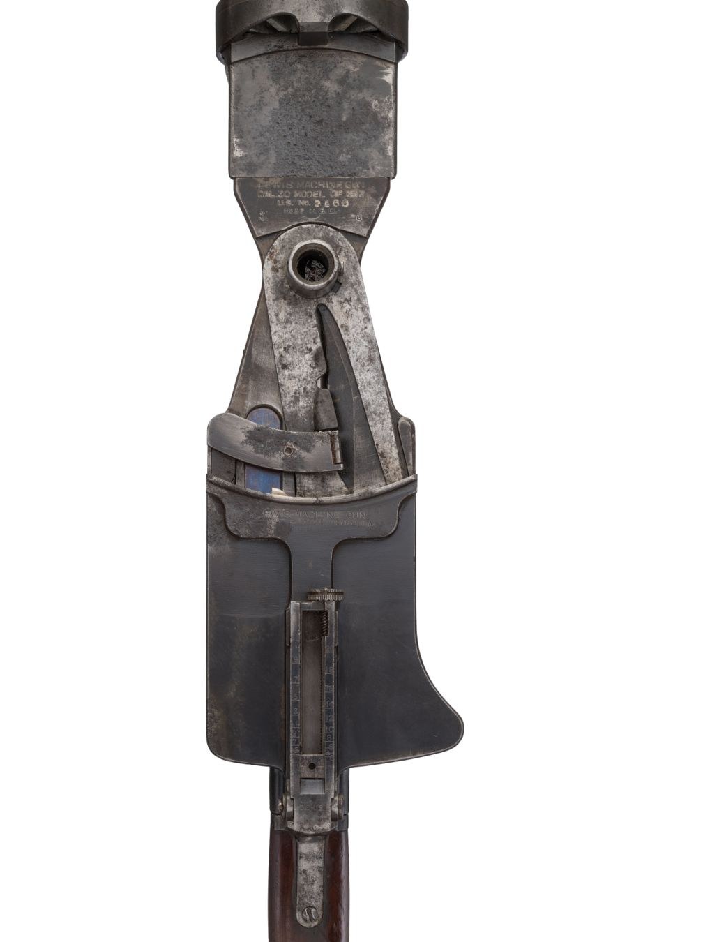
Because the pan only moves when the gun moves it, an empty pan turns freely by hand on the gun. Pridham uses that as a test: “An Empty Magazine rotates freely on the Gun. If resistance is met with, this is caused by a Live Round coming up against the Cartridge Stop on the Feed Arm.”2 The immediate-action drills in Volume 7 are built on it.
3.11 Trigger, sear, and the absent selector
The trigger group slides into grooves under the body and carries the trigger, the sear, the butt catch and, on the British gun, a plunger. The Textbook of Small Arms describes the arrangement: “the trigger is connected with a pivoted sear, the nose of which holds back the piston until it is lowered by the partial rotation of the sear when the trigger is pressed.”4 Pridham notes a detail that separates the two national patterns: “The .300 Gun has the Spring fitted to the Sear, and not to the Trigger, as in the .303 Gun.”2
There is no selector. The Savage handbook’s section headed “Semi-automatic fire” is one instruction: “To fire single shots press trigger and release immediately. To release quickly enough for a single shot requires some practice.”1 Pridham’s figure for aimed fire by a trained gunner is “150 rounds per minute”, against a mechanical rate of about ten rounds a second.2
3.12 Safety and dust cover
The safety is a sliding plate. The RAF notes: on each side of the body is a slot for the cocking handle’s shank, and “Each slot can be covered by a plate sprung into position and moved vertically by a thumb-piece. This plate serves as a Safety Catch or Dust Protector, the recesses in it holding the cocking-handle, whether in the forward or backward position.”3 The Textbook: “A notched ‘safety plate’ which, when applied, retains the piston by fixing the position of the cocking handle.”4
Savage’s procedure, with the gun cocked: push the safety up “until its rear notch encloses the shank of the charging handle”, then pull the trigger so that the handle moves forward into the undercut at the front of the slot; “In this position the gun is locked at ‘Safe.’” Raising the safety with the handle forward closes the action against “dust, sand, water”, and the handbook recommends carrying the gun that way, chamber empty and magazine on.1 The handbook also gives the one caution every open-bolt gun shares: “Never let the charging handle forward by hand so that the bolt rests on a loaded cartridge in the chamber.”1 Pridham’s rule of thumb follows from the open bolt: with a filled magazine on, when the cocking handle “is fully forward … Gun is ‘Safe’”, and when it is to the rear, “Gun is Loaded”.2
The handle could be on either side on some guns. Pridham notes that “The .300 (American type) Lewis Gun has Cocking Handle on left side of Body”; the US handbook on the Japanese Model 92 says that its handle “is on the left and that there is no provision allowing it to be changed to the right side of the gun”, which implies the British gun had that provision.211
3.13 Cooling
The radiator is the gun’s most famous feature and the one with the most extravagant claims attached.
The construction, from the RAF notes: around the barrel is “the Radiator, which is of aluminium, has projecting flanges, and is split longitudinally”; around that, a radiator casing in front and rear portions joined by a clamp ring; “The front portion is tapered, and extends beyond the barrel mouthpiece.”3 The mouthpiece screws onto the muzzle with a left-hand thread “to prevent it from working loose”.3
How it works, in the period’s words:
- Savage: cooling by “a radiator having high longitudinal radial fins”, made of aluminium, “a metal of high thermal conductivity”, and “by mechanically sucking columns of air along these radiating surfaces by using the muzzle blast of firing as a suction pump.”1
- “Simplex”: the shape of the mouthpiece and the front casing “causes a draught to be set up by the gases as they rush forward. This draught sucks cool air from the breech end of the radiator, under the rear radiator casing, towards the muzzle”.5
- Pridham: the gases expanding out of the mouthpiece’s “Cone-shaped Interior” strike the fore radiator casing, “expelling all the Air in front of them. This causes Suction behind them, and draws Cool Air through the Flanges of the Radiator.”2
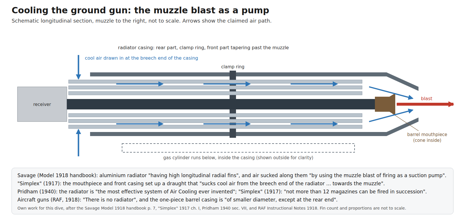
The claims made for it vary widely. Pridham, in 1940: “the most effective system of Air Cooling ever invented”, which “enables the Lewis Gun to fire, at a rate of 10 rounds per second, for a prolonged period. No Barrel Changing is necessary.”2 The 1916 General Staff pamphlet S.S. 122: the gun “will be red hot if 700 or 800 rounds are fired rapidly. If more are fired they may burst.”12 “Simplex”, 1917: “not more than 12 magazines can be fired in succession”.5 The two 1916–17 sources describe the gun as used in France; Pridham’s is an instructor’s advocacy. Twelve magazines is 564 rounds, which sits close to S.S. 122’s 700 to 800.
“Simplex” adds a claim for the system that no other source repeats: that the mouthpiece and casing prolong the gas pressure on the bullet, so that “The bullet is found to have a greater velocity than is the case with a rifle of the same length of barrel”, and that the gases striking the casing reduce recoil “to a minimum”.5 No measurement is given, and the claim is recorded, not endorsed.
The aircraft gun did without all of it. The RAF notes: “There is no radiator, and the casing is of smaller diameter, except at the rear end”.3 American Machinist: “The radiator is not required on the airplane model”.6
3.14 Sights
The ground gun’s back sight is a leaf on the body cover. Savage graduates it “up to 2100 yds.” with “Distance between sights 32.177"".1 Rock Island Auction’s catalogue of a BSA gun describes its folding rear sight as “graduated to 1900 yards”.13 The two numbers describe two guns, a .30-06 Savage and a .303 BSA, and are not in conflict. The foresight sits on the clamp ring, which the RAF notes describe as “turned up at both ends to form a foresight protector”.3 Aircraft guns used a ring sight and the Norman wind-vane foresight (Volume 2).
3.15 What could not be established
- The aircraft magazine’s capacity: 97 in both 1918 primary sources; 96 in Chinn’s text; “about 94” in Pridham. This dive uses 97.
- The “greater velocity” claim of “Simplex”: no measurement found.
- Which British guns could take the cocking handle on the left: implied by the 1944 US handbook, stated by no British source consulted.
- The free-travel figure in the Savage handbook: the printed fraction is illegible in the only scan; Chinn’s 1.0625 in is used.
References
Footnotes
-
Savage Arms Corporation, Hand-Book of the Lewis Machine Gun, Model 1918, Caliber .30 (Utica, N.Y., c. 1918), pp. 7–39. https://www.forgottenweapons.com/wp-content/uploads/Lewis/lewismanual.pdf, consulted 2026-10-19. ↩ ↩2 ↩3 ↩4 ↩5 ↩6 ↩7 ↩8 ↩9 ↩10 ↩11 ↩12 ↩13 ↩14 ↩15 ↩16 ↩17 ↩18 ↩19 ↩20 ↩21
-
Major C. H. B. Pridham, Lewis Gun Mechanism Made Easy, with notes on the .300 (American) Lewis Gun, 6th edition (Aldershot: Gale & Polden, November 1940; 18th impression March 1941), sections I to VII and coloured plate. https://www.forgottenweapons.com/wp-content/uploads/Lewis/Lewis%20Gun%20Mechanism%20Made%20Easy.pdf, consulted 2026-10-19. ↩ ↩2 ↩3 ↩4 ↩5 ↩6 ↩7 ↩8 ↩9 ↩10 ↩11 ↩12 ↩13 ↩14 ↩15 ↩16
-
Royal Air Force, Instructional Notes on the Lewis Gun (April 1918), section II, General Description. https://archive.org/details/raflewisgun, consulted 2026-10-19. ↩ ↩2 ↩3 ↩4 ↩5 ↩6 ↩7 ↩8 ↩9 ↩10 ↩11 ↩12 ↩13 ↩14 ↩15 ↩16 ↩17
-
War Office, Textbook of Small Arms 1929 (HMSO), chapters on machine-gun mechanisms and cartridge head space. https://archive.org/details/textbooksmallarms1929, consulted 2026-10-19. ↩ ↩2 ↩3 ↩4 ↩5 ↩6
-
“Simplex”, Instruction on the Lewis Automatic Machine Gun, 3rd edition (Forster Groom, 1917), chapters I, V, VI and X. https://archive.org/details/instructionlewisautomaticmachinegun1917, consulted 2026-10-19. ↩ ↩2 ↩3 ↩4 ↩5 ↩6 ↩7 ↩8
-
“The Manufacture of the Lewis Machine Gun”, American Machinist, 6 December 1917 to 6 June 1918. https://archive.org/details/Ame-mach-lewis-gun, consulted 2026-10-19. ↩ ↩2 ↩3 ↩4
-
George M. Chinn, The Machine Gun, vol. I, Part IV, chapter 1 (Bureau of Ordnance, 1951). https://www.ibiblio.org/hyperwar/USN/ref/MG/I/MG-4.html, consulted 2026-10-19. ↩ ↩2 ↩3
-
Isaac N. Lewis, US Patent 1,142,896, “Automatic firearm”, filed 16 April 1912, granted 15 June 1915. https://patents.google.com/patent/US1142896A/en, consulted 2026-10-19. ↩
-
Australian War Memorial, “Lewis Mk 1 Light Machine Gun: Sergeant S R McDougall VC, MM”, RELAWM C239470. https://www.awm.gov.au/collection/C239470, consulted 2026-10-19. ↩
-
J. David Truby, A Pictorial History of the Lewis Gun (Paladin Press, 1976). https://archive.org/details/lewis-gun-paladin, consulted 2026-10-19. ↩
-
US War Department, Handbook on Japanese Military Forces, TM-E 30-480 (1 October 1944), chapter IX, section II, 2.e. Lone Sentry transcription, https://lonesentry.com/manuals/handbook-japanese-military/japanese-machine-guns.html, consulted 2026-10-19. ↩
-
General Staff, Some Notes on Lewis Guns and Machine Guns, S.S. 122 (September 1916). https://archive.org/details/1916-uk-ss-122, consulted 2026-10-19. ↩
-
Rock Island Auction Company, sale 73, lot 3393, “BSA Co Lewis Machine Gun Mk II”, catalogue description. https://www.rockislandauction.com/detail/73/3393/bsa-co-lewis-machine-gun-mk-ii, consulted 2026-10-19. ↩
Comments (0)