Girardoni Air Rifle · Volume 5
How It Works, and How the Army Said to Keep It Working
The flask, the valve, the striker and the three-click lock; the gravity magazine and the sliding bar; the 1788 regulation as an owner's manual, with its spoonful of water; and what is known about taking one apart, the faults it develops and what can be repaired
This volume explains the mechanism of the Austrian military rifle and how its users were told to look after it. The sources are Haller’s 1891 printing of the army’s own 1788 regulation, Robert Beeman’s descriptions of the rifle he owned and had dismantled, and the analysis of the lock by Geoffrey Baker and Colin Currie as Beeman reports it.12 Baker and Currie’s own book, the standard technical study, was not available; where its findings are used they are labelled as reported.3 The hub’s Daisy dive explains pre-charged pneumatic powerplants in general (Daisy, Volume 5), and that ground is not repeated here.
5.1 The parts
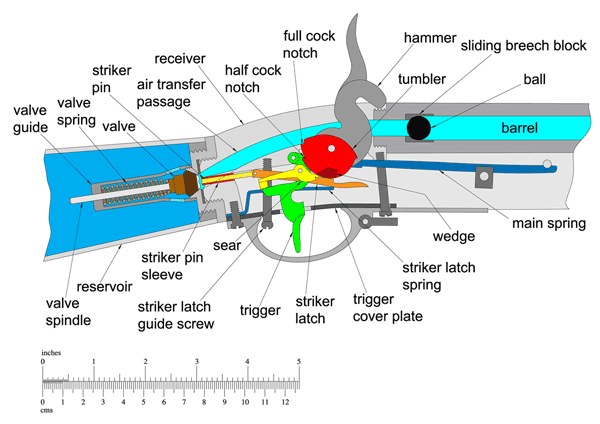
The 1788 regulation says that “the gun consists of two parts: the first comprises the barrel, the ball tube and the lock; the second the flask, which at the same time forms the stock.”1 In more detail, using the names Baker’s diagrams give the parts:2
Table 1 — The parts
| Part | What it is | Material, per Beeman |
|---|---|---|
| Barrel | Octagonal, rifled, 12 shallow grooves | Wrought iron; rifling about 0.005 in deep |
| Magazine tube (“Kugelröhre”) | Tube along the right of the barrel, 20 balls; lid at the front | Iron |
| Loading bar (“Verschlusskeil”, the wedge) | Square-section bar sliding across the breech, with a ball socket and a button at each end | Steel; fitted so closely, Beeman says, that it would slide into its airtight position under its own weight |
| Flat spring | Along the outside of the magazine, holding the bar to the rifle’s left | Steel |
| Receiver (“lock housing”) | One-piece casting forming the top of the action; air passage inside; threaded boss at the rear | Cast brass or bronze; the lower half of the action is formed only by the stock wood and trigger guard |
| Lock | Hammer (cocking lever), tumbler with a wedge and a roller, sear, bridle, a heavy flat mainspring | Iron and steel |
| Striker assembly | Striker latch, striker pin, striker latch guide screw | Steel pin in an iron-lined sleeve |
| Flask (“Windflasche”) | Tapering iron reservoir forming the butt, screwed onto the receiver | Riveted and brazed iron sheet, coated inside and out with brazing metal |
| Flask cap and valve | Brass cap screwed into the flask mouth carrying the valve: spindle, brass coil spring, three stacked hard-leather discs cut to a 60° cone, seating on a brass seat | Brass, leather |
| Gasket | Between flask and receiver | Cow horn, honed flat |
5.2 The air system: flask, valve and striker
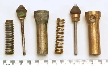
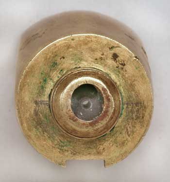
The flask is a closed iron vessel, wide and round at the back (the “bag” Thomas Rodney saw in 1803) and tapering forward to a mouth closed by a brass cap. The cap carries the valve on its inner face, so the valve sits inside the flask, in its air. The valve’s head is a stack of three hard-leather discs shaped to a cone and pressed forward onto a brass seat in the cap by a coil spring of brass. Beeman notes that the spring is brass because condensed moisture in the flask would rust iron or steel.2 Haller’s footnote adds that Girandoni began with a leather flask valve and replaced it with a brass one.1
The flask screws onto a threaded boss at the back of the receiver, sealed by a cow-horn gasket. When it is screwed home, the end of a striker pin, sliding in a sleeve on the rifle’s axis, lies against the valve head through the cap. From the boss, a passage in the brass casting, drilled and filed out on Beeman’s rifle and described as a curved tunnel cast in on Baker and Currie’s replica receiver, leads forward and upward to the breech, where the ball sits in the loading bar.2
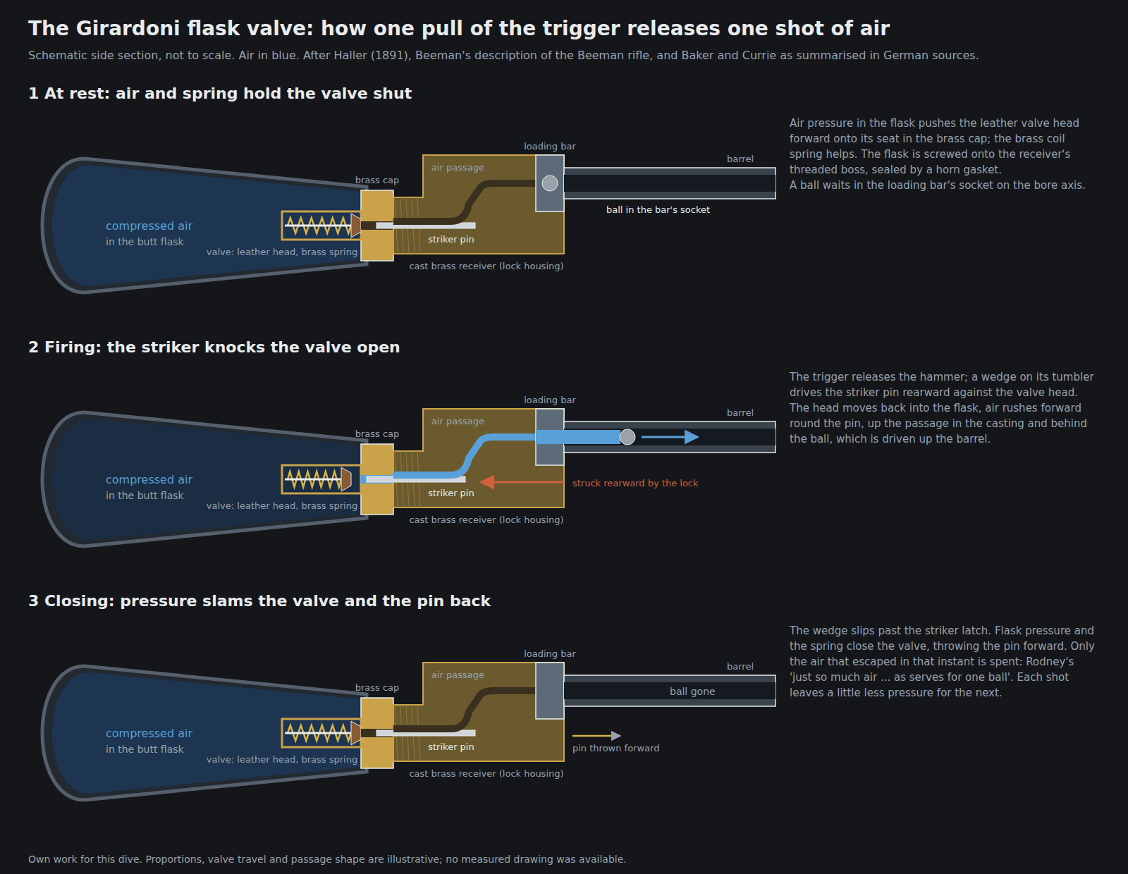
The principle is the one that governs every pre-charged airgun since: the pressure in the reservoir holds the valve shut, and a blow opens it for an instant. The harder the air pushes, the harder the blow must be. That is why the lock has a heavy flat mainspring, much stronger than a flintlock’s, and why Beeman and Baker and Currie credit it with letting the Girardoni use higher pressures than lesser air guns of the period.2 It is also why, as the flask empties, each shot uses a little more air than the last: with less pressure behind it, the valve stays open longer. Beeman describes the end of a charge: the valve “stays open longer on each shot until finally the last air is released all at once”.2
5.3 The lock: three clicks
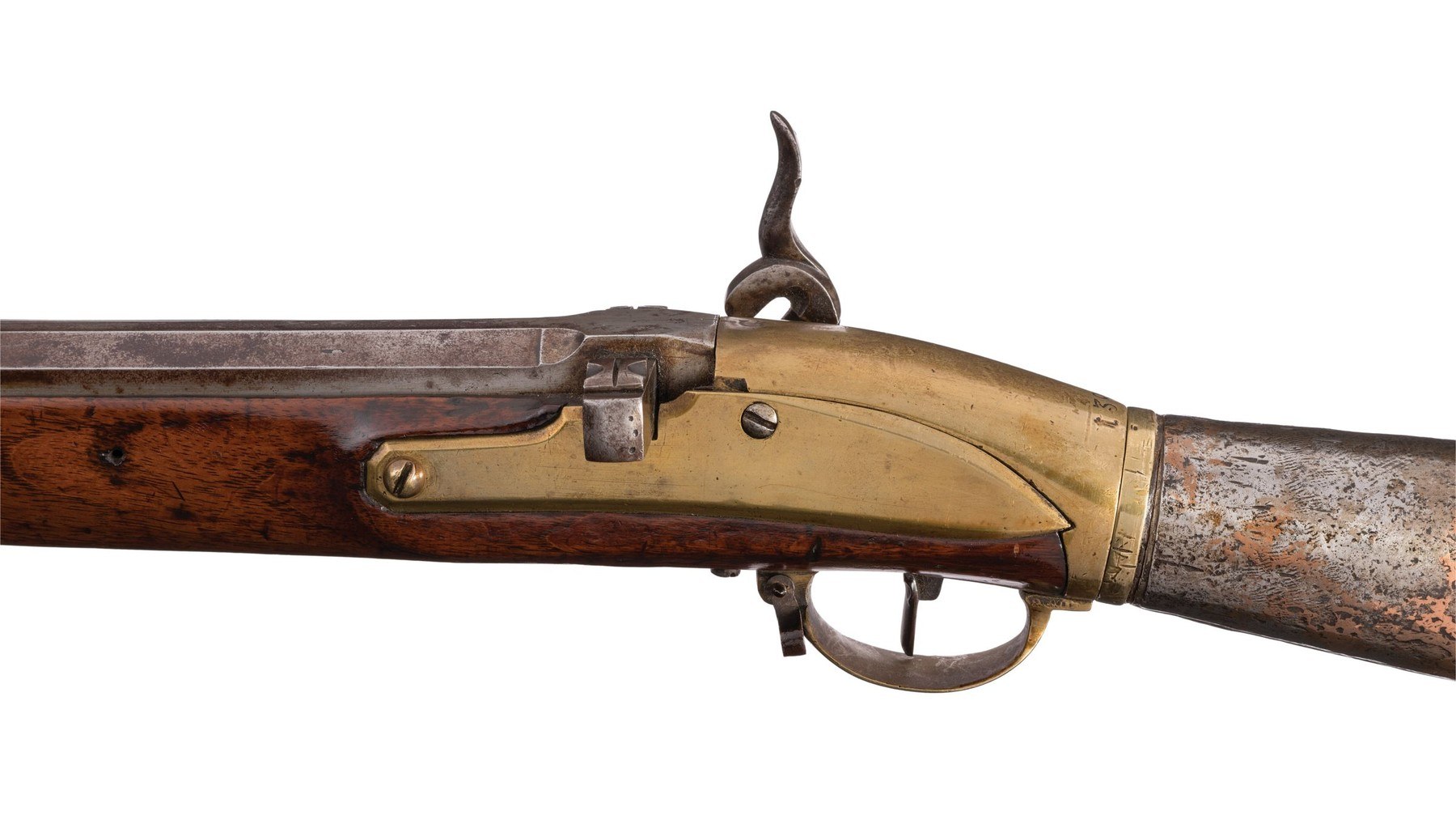
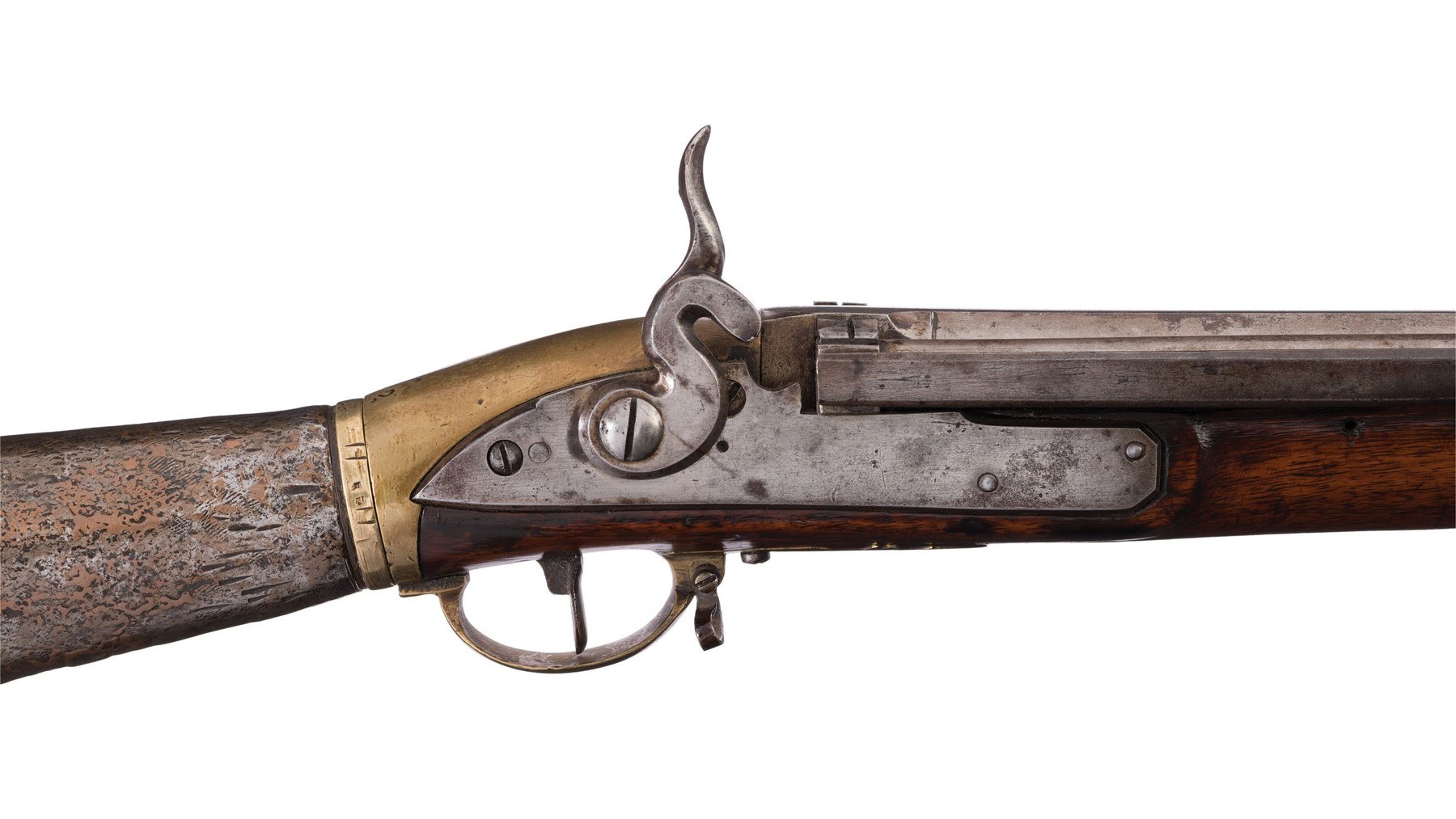
The lock looks like a flintlock’s from outside, with an S-shaped hammer on the right, but inside it does a different job. There is no flint and no frizzen. The hammer is a cocking lever. Its tumbler carries a wedge and, in Baker’s drawings, a small roller bearing on a flat mainspring that lies along the forward two-thirds of the lock plate.2
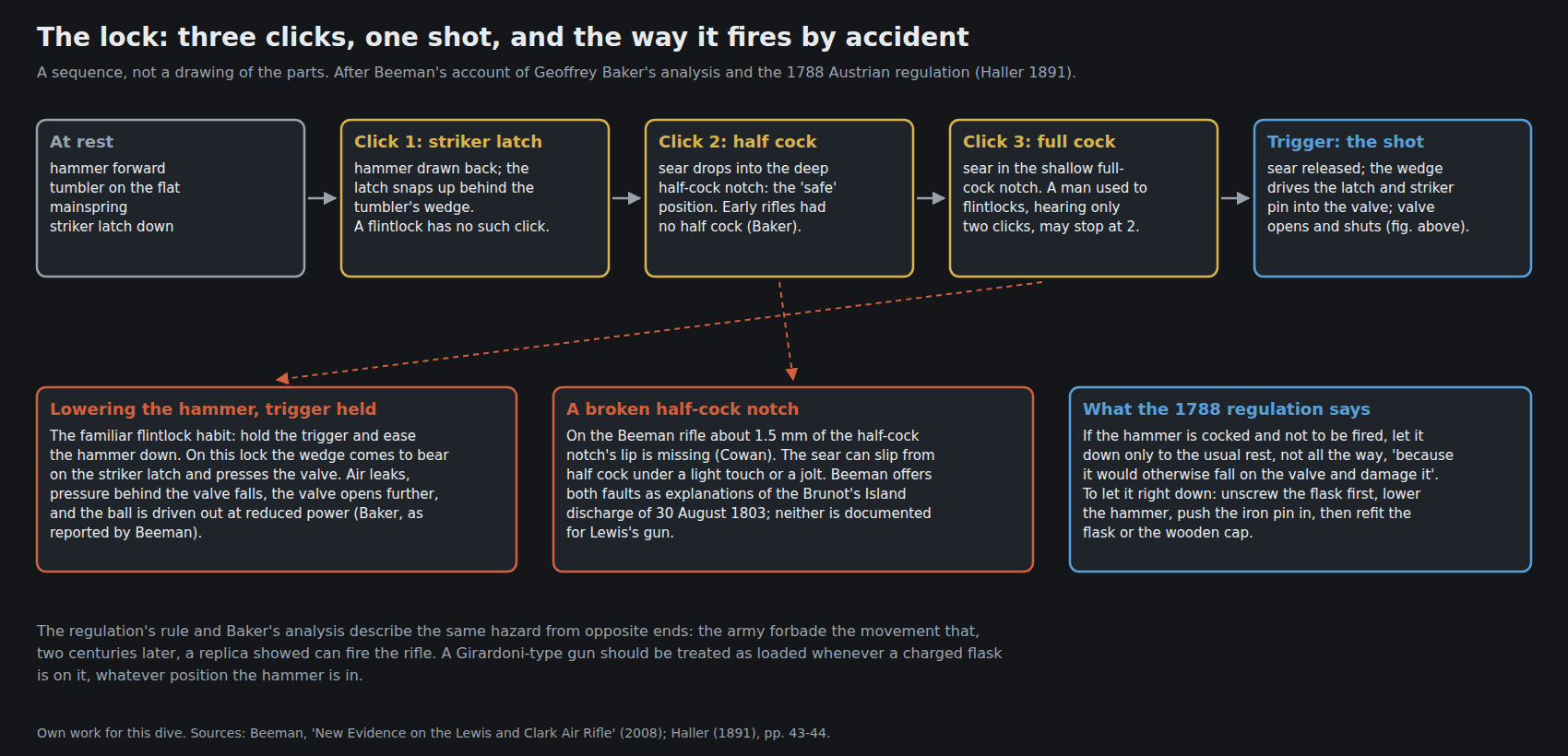
Cocking makes three clicks, where a flintlock makes two:2
- The striker latch. As the tumbler turns, a sprung latch connected to the striker snaps up behind the wedge. A flintlock has nothing equivalent.
- Half cock. The sear drops into a deep half-cock notch, the “safe” position. Baker found that early production had no half cock.
- Full cock. The sear drops into a shallow full-cock notch.
When the trigger releases the sear, the mainspring drives the tumbler round; the wedge catches the striker latch and drives the latch, and with it the striker pin, rearward against the valve; the valve opens; the wedge rides up out of the latch’s notch; and the valve, pushed by pressure and its spring, slams shut and throws the pin forward again. On re-cocking the wedge passes the latch without moving it.2
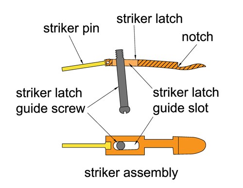
The third click is where the rifle catches out men used to flintlocks. A flintlock is at full cock on its second click; on this lock the second click is half cock. Beeman suggests that a shooter stopping at two clicks and pulling hard on the trigger could break the half-cock notch, and that the Beeman rifle’s broken notch may have happened exactly that way (Volume 4).2
The more serious hazard is lowering the hammer. Baker and Currie found, according to Beeman, that if the hammer is let down from cock while the trigger is held, as any flintlock user would do to make the gun safe, the wedge comes to bear on the striker latch and presses the valve. Air leaks past, the pressure holding the valve shut falls, the valve opens further, and in a rapidly building cycle the gun fires, at reduced power. Baker had it happen to a replica in early 2004, without a ball, and the noise made Currie jump.2
The Austrian army knew this in 1788. Its regulation says:1
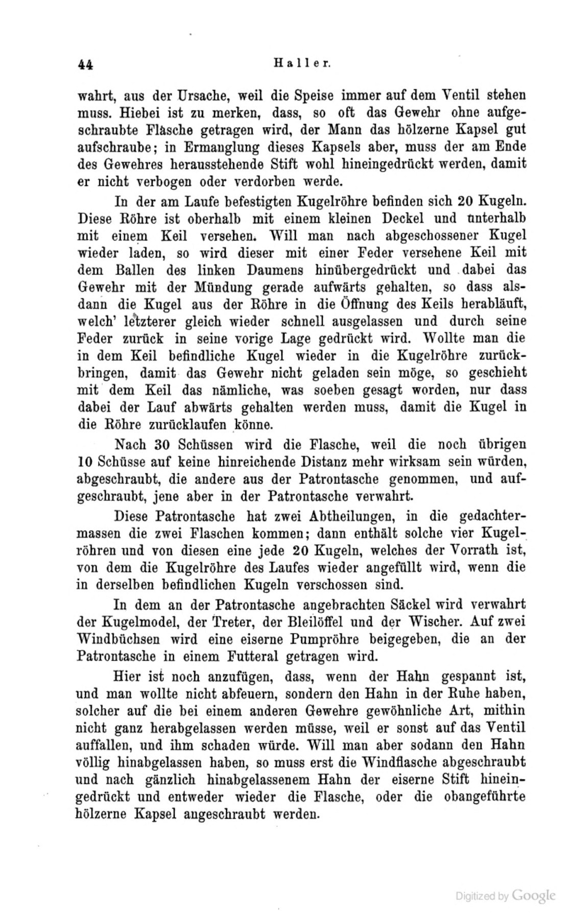
“Hier ist noch anzufügen, dass, wenn der Hahn gespannt ist, und man wollte nicht abfeuern, sondern den Hahn in der Ruhe haben, solcher auf die bei einem anderen Gewehre gewöhnliche Art, mithin nicht ganz herabgelassen werden müsse, weil er sonst auf das Ventil auffallen, und ihm schaden würde. Will man aber sodann den Hahn völlig hinabgelassen haben, so muss erst die Windflasche abgeschraubt und nach gänzlich hinabgelassenem Hahn der eiserne Stift hineingedrückt und entweder wieder die Flasche, oder die obangeführte hölzerne Kapsel angeschraubt werden.”
“It should be added that if the hammer is cocked and one does not want to fire but to have the hammer at rest, it must be let down in the way usual with another gun, and so not all the way down, because otherwise it would fall onto the valve and damage it. But if one wants the hammer right down, the air flask must first be unscrewed, and with the hammer fully down the iron pin pushed in, and then either the flask or the wooden cap mentioned above screwed back on.”
The regulation’s reason is damage to the valve, not an accidental shot, but the instruction prevents both. It also shows the safe way to make the rifle harmless: take the flask off.
5.4 The magazine and the loading bar
The magazine is a tube along the right side of the barrel holding twenty balls, with a small lid at its front end and the loading bar at its rear. There is no follower and no magazine spring: the balls move only by gravity. The bar is a square-section steel bar running right across the breech, with a hole through it, the socket, big enough for one ball. A long flat spring lying along the outside of the magazine bears on the bar’s right-hand end and holds it to the rifle’s left, where its socket is in line with the bore.12
The regulation describes loading:1
“Will man nach abgeschossener Kugel wieder laden, so wird dieser mit einer Feder versehene Keil mit dem Ballen des linken Daumens hinübergedrückt und dabei das Gewehr mit der Mündung gerade aufwärts gehalten, so dass alsdann die Kugel aus der Röhre in die Öffnung des Keils herabläuft, welch’ letzterer gleich wieder schnell ausgelassen und durch seine Feder zurück in seine vorige Lage gedrückt wird.”
“To load again after a ball has been fired, this sprung wedge is pressed across with the ball of the left thumb, the gun being held with the muzzle straight up, so that the ball runs down out of the tube into the opening in the wedge; the wedge is then quickly released and pushed back into its former position by its spring.”
And unloading: to return the ball from the socket to the tube “so that the gun is not loaded”, do the same with the bar but with the barrel held downward, so the ball rolls back.1
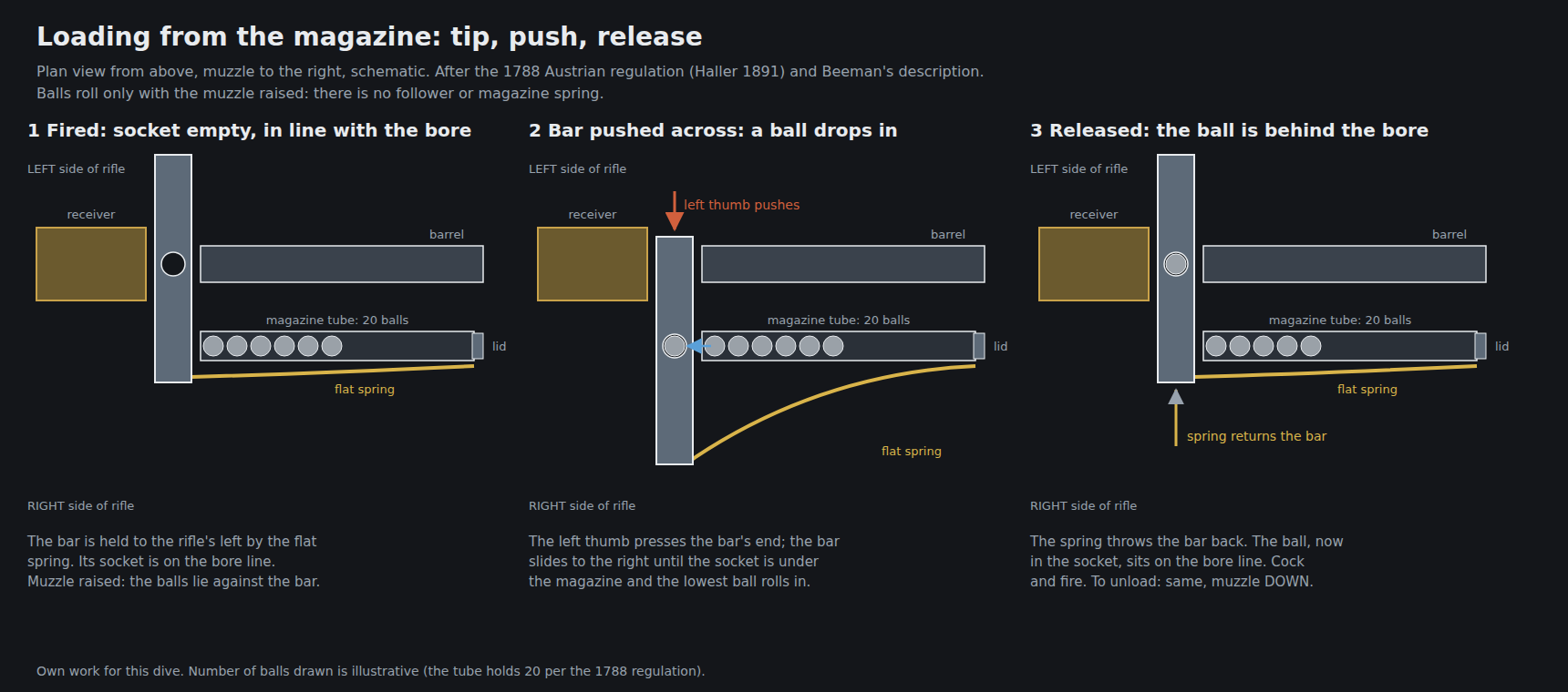
Because the balls ride on gravity, the rifle can be loaded lying down, as long as the muzzle can be raised: a real advantage over a muzzle-loader that Haller’s sources and later writers both emphasise.14 The same gravity feed is why Beeman argues that a forty-ball magazine was never built: in a long, partly filled tube the soft balls would slam back and forth and deform.2
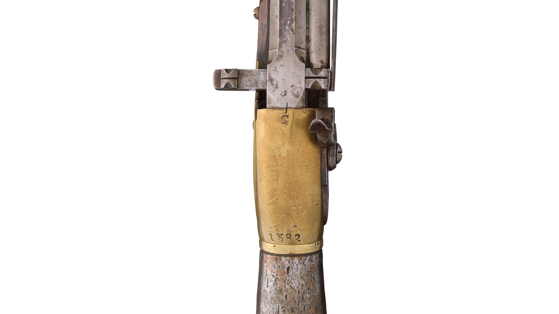
The two sides of the lock, from Rock Island Auction’s photographs of the same rifle:
5.5 The cycle of fire, step by step
From a charged flask on the rifle and twenty balls in the tube:
- Raise the muzzle. The balls roll back against the loading bar.
- Press the bar’s left button across with the left thumb. The socket moves under the magazine and the lowest ball drops in.
- Release. The spring returns the bar; the ball is on the bore line, sealed in the breech by the close-fitting bar.
- Cock with the right thumb, through three clicks to full cock.
- Aim and pull the trigger. The wedge drives the striker pin into the valve; a measured burst of air drives the ball. Beeman notes that with practice the left hand can load while the right cocks, “enabling aimed shots to be taken about every 1 1/2 seconds”, a figure from his own shooting of a reproduction.2
- Repeat; each shot takes a little more of the flask’s falling pressure.
- After 30 shots, change flasks, the regulation says, because the last ten would not carry far enough (Volume 6).1
- Refill the magazine by opening its lid and emptying in one of the tin ball tubes (the pouch carried four of twenty).1
5.6 The 1788 regulation: the only manual
The “Vorschrift zum Gebrauche der Windbüchse”, the regulation for the use of the air rifle, sent by Joseph II to Hadik on 7 February 1788 and printed in full by Haller, is the only contemporary manual found for this rifle.1 It is short and practical. Its instructions not already covered:
Water in the flask. “After about 100 shots the air rifle must be given again its so-called Speise (‘food’), which consists of plain water.” The method: draw the pump rod out far enough that “a moderate spoonful of water” fits in the pump tube; fix the flask on the pump; press the water into the flask with the first stroke; then pump. The water’s purpose, which the regulation does not spell out but its next instruction implies, is to keep the leather valve wet and tight: flasks were to be stored so that “the Speise always stands on the valve”.1
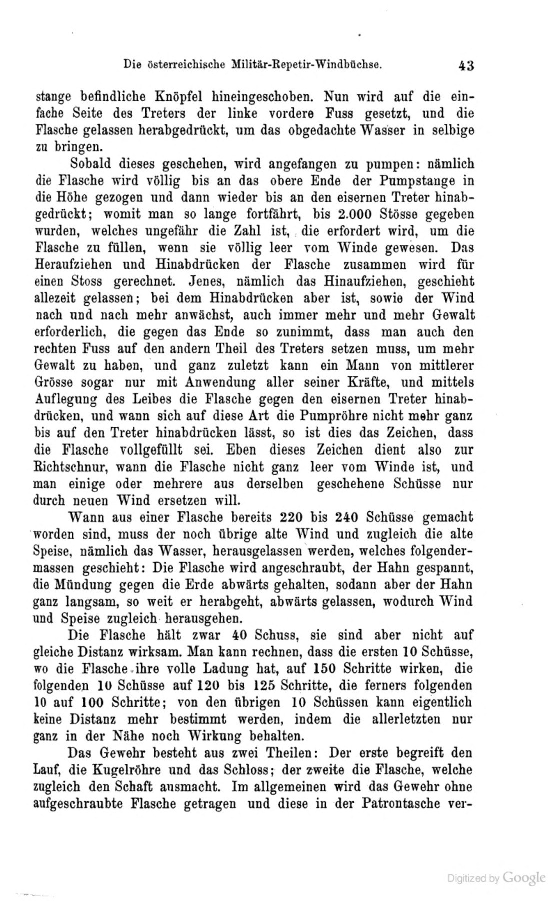
Pumping. Pull the flask up the pump rod to its top, press it down to the iron foot-plate (one stroke), and continue “until 2,000 strokes have been given, which is about the number required to fill the flask when it was entirely empty of wind”. As the pressure builds, pressing down needs more and more force, until the man must put his right foot on the foot-plate too, and “at the very last a man of middling size can press the flask down against the iron foot-plate only with all his strength and by laying his body on it”. When the pump will no longer go all the way down to the plate, the flask is full; the same sign tells a man when to stop topping up a partly used flask.1 Volume 6 discusses what this means for the pressure.
Emptying old air. “When 220 to 240 shots have been made from a flask, the remaining old wind and at the same time the old Speise, that is the water, must be let out”: screw the flask on, cock, hold the muzzle toward the ground, and let the hammer down “very slowly, as far as it will go”, so that air and water escape together.1 This is the one occasion on which the regulation tells the soldier to let the hammer press the valve on purpose.
Carrying. The rifle was normally carried without its flask, the flask kept in the pouch “because the Speise must always stand on the valve”. With the flask off, the soldier was to screw on the wooden cap, or failing that push in the pin protruding from the end of the action “so that it is not bent or spoiled”.1
The pouch. Two compartments for two flasks, and four ball tubes of twenty. A small bag on the pouch held the bullet mould, a “Beter” (the word is printed so; its meaning is not clear), the lead ladle and the wiper. “One iron pump is issued to two air rifles”, carried in a case on the pouch.1
5.7 Taking one apart: what is known
No maker’s or armourer’s manual for dismantling the rifle has been found. The 1788 regulation covers only removing and fitting the flask. What follows is assembled from Beeman’s descriptions of his own rifle and of Ernest Cowan’s work on it, and from Baker and Currie’s findings as Beeman reports them. It is a description of how the parts come apart on one rifle, not a tested procedure, and it is offered so that a reader knows what to look for, not as instructions for an original.2
First, the flask. It unscrews from the receiver’s threaded boss, against the horn gasket. With the flask off the rifle is inert. The regulation’s wooden cap or the pushed-in pin protects the striker end.1
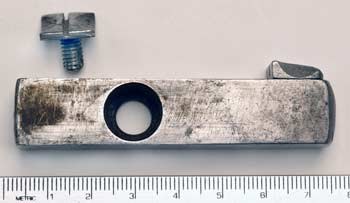
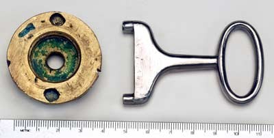
The flask valve. The brass cap, with the valve assembly threaded onto its inner face, unscrews from the flask’s mouth with a special key engaging the cap’s face. Beeman illustrates the cap of his rifle with a key made for it by Cowan in 2004.2 Only an empty flask should ever be opened (section 11).
The lock. The lock plate comes off in the usual way for a side lock, by its screws. Beeman found that the plate on Girardoni locks has a small hole whose purpose Baker and Currie’s study revealed: a drift punch through the hole restrains the flat mainspring, because “a traditional spring clamp, designed to compress the V-shaped mainspring found in most flintlock firearms, cannot be used to restrain a flat mainspring”. Without it the spring is released suddenly and can break.2 Beeman’s photograph of his rifle’s lock shows a drift punch in place. He records too that the receiver has a small ledge, the “little Girandoni notch”, that locates the rear of the lock plate.
The striker assembly. With the lock plate off, Beeman says, it is “easy to … loosen the striker latch guide screw behind the trigger, and thus slip out the striker assembly for easy and rapid cleaning”. The guide screw “has no adjustment role” but sometimes works loose.2
The loading bar. It is held by retaining screws whose grooved heads sit on top of each end of the bar housing; with one removed the bar can be withdrawn. Before the flat spring was refitted, the bar on Beeman’s rifle would slide into its seated position under its own weight, so precisely was it tapered.2
The magazine. Its lid turns off with a key (illustrated above).
The barrel and stock. The receiver casting forms only the top of the action; the stock wood and the separate trigger guard form the bottom, which Beeman calls “a potentially weak area of the design”. The forend is held to the barrel by pins through lugs under the barrel, one of which, on the Beeman rifle, had been torn open (Volume 4).2
5.8 Detail strip: what a correct procedure must account for
Because no tested procedure was found, the points any procedure would have to respect are set out instead, each from a source:
- The flask comes off first and stays off. The regulation makes the flask-off state the safe one, and Baker’s finding about the lowered hammer shows why.12
- Restrain the flat mainspring with a punch through the plate’s hole before taking the lock apart, not with a V-spring clamp.2
- Mind the assembly marks. Beeman found “a punched or drilled series of pits” matching on all key parts of his rifle, “the same special military assembly marks found on other authentic specimens”, and noted that a replacement spring carried chiselled marks instead.2 Parts are fitted to each other, not interchangeable.
- Do not use a steel rod in the bore. The rifling is very shallow, about 0.005 in according to Beeman, and the originals had wooden rods with bone tips used only for cleaning and pushing back stuck balls; “steel rods are NOT original; guns with steel rods should be examined for damage” to the rifling.2
- The valve leather and horn gasket are probably original and irreplaceable on an antique; drying them out will ruin the seal.
5.9 Maintenance
What the sources say an owner of the period did, and what modern handlers report:
Table 2 — What the sources say an owner of the period did, and what modern handlers report
| Task | Interval or occasion | Source |
|---|---|---|
| Water (“Speise”) into the flask | About every 100 shots | 1788 regulation1 |
| Store and carry flasks valve-down | Always | Regulation; Haller’s note on packing1 |
| Release old air and water | After 220–240 shots per flask | Regulation1 |
| Wooden cap on when flask is off | Always | Regulation1 |
| Keep striker pin polished and lubricated | Soldiers were “trained to keep these pins polished and lubricated” (Beeman, unsourced) | Beeman2 |
| Oil the pump’s leather seals; adjust by the nut | When pumping; seals pushed out for oiling, nut expands them | Beeman, on Cowan’s copy of the pump2 |
| Wooden rod only in the bore | Always | Beeman2 |
| Keep flasks wet with water “now and then” so the valve leather stays tight | Occasionally | German Wikipedia, after Baker and Currie5 |
The regulation’s water treatment deserves emphasis because no modern airgun does anything like it. It addressed a real problem: a leather seat that dries out leaks. The cost was water inside an iron flask, which is why the flasks were coated in brazing metal inside and out and why the valve spring is brass.2
5.10 Faults, failures and repair
The faults recorded by users and examiners, with what the sources say about each:
Table 3 — The faults recorded by users and examiners, with what the sources say about each
| Fault | Symptom | Cause given | Remedy given | Source |
|---|---|---|---|---|
| Whole charge lost at once | ”lost the whole charge of air at the first fire” | Low pressure lets the valve stay open; or a sticking striker pin | Recharge; free the pin | Rodney via Beeman; Beeman’s analysis2 |
| Striker pin sticks | Gun will not fire, or dumps air | Condensation corrosion of steel pin in iron sleeve at low pressure | Work the hammer with trigger held on an empty flask; or remove and clean the striker assembly | Beeman2 |
| Loose striker latch guide screw | Erratic firing | Screw beaten loose | Tighten | Beeman2 |
| Fires on lowering the hammer | Unintended discharge at reduced power | Wedge bears on the striker latch | Never lower with a charged flask on; take the flask off | Regulation; Baker via Beeman12 |
| Broken half-cock notch | Fires from half cock on a touch | Hard pull at half cock mistaken for full cock | New tumbler or notch repair (gunsmith) | Beeman2 |
| Broken mainspring | Lock will not cock or fire | Breakage; Beeman suggests careless disassembly without the punch | New spring | Lewis’s journal, 9–10 June 1805; Beeman62 |
| Leaking flask valve | Flask will not hold | Dry or worn leather | Water feed; new leathers | Regulation; Beeman12 |
| Cracked or failed flask | Flask will not hold, or bursts | Faulty iron, seams | Replace the flask; the army issued three per rifle and a 10 per cent reserve | German Wikipedia after Baker and Currie (about 30% failed proof); Haller51 |
| General wear in the field | ”So spoiled that the man can no longer use it” | Untrained handling | A winter’s repair by specialist gunsmiths | Colloredo, 1789, in Haller1 |
The army’s answer to repair was organisational: two skilled journeymen sent with the first 200 rifles in 1787, gunsmiths and tool chests with the Tyrolean corps in 1793, a whole winter of repairs in 1788–89 (Volume 2).1 Beeman, via Hummelberger and Scharer, adds a journeyman gunsmith for every hundred rifles and stocks of spare seals, flasks and mainsprings.2 For an original today there are no spare parts. Ernest Cowan made patterns and castings for his four museum copies of the Beeman rifle, and Beeman’s photographs show the receiver, thimbles, flask and pump being made from them; any part for an original would have to be made the same way, by a specialist, and fitted to it.2
5.11 An original is not to be charged
Beeman, who owned the most closely studied military Girardoni in America, would not test it. Describing the rifle as “still … in fine firing condition”, he added the exception: “except for possible, not easily detected, age weakening or corrosion of the inside of the air reservoir. This alone would preclude any present firing tests.”2 His own test-firing was done with Cowan’s reproductions.
The flasks are riveted and brazed iron sheet more than two hundred years old, made of iron that the Austrian army itself found variable (Volume 6), filled for years with water by regulation, and holding, when full, enough stored energy to kill (Volume 8 gives the arithmetic). An original flask should never be charged. The reasons, and what a modern reservoir for a reproduction must be instead, are set out in Volume 8.
References
Footnotes
-
August Haller, “Die österreichische Militär-Repetir-Windbüchse des vorigen Jahrhunderts. Nach Originalacten zusammengestellt”, Organ der Militärwissenschaftlichen Vereine, vol. 42 (Vienna, 1891), pp. 34–45, printing the “Vorschrift zum Gebrauche der Windbüchse” (1788) at pp. 42–44. Internet Archive item bub_gb_XF0-AQAAMAAJ, https://archive.org/details/bub_gb_XF0-AQAAMAAJ . Accessed 2026-10-18. Translations are this dive’s. ↩ ↩2 ↩3 ↩4 ↩5 ↩6 ↩7 ↩8 ↩9 ↩10 ↩11 ↩12 ↩13 ↩14 ↩15 ↩16 ↩17 ↩18 ↩19 ↩20 ↩21 ↩22 ↩23 ↩24 ↩25 ↩26 ↩27
-
Robert D. Beeman, “New Evidence on the Lewis and Clark Air Rifle” (updated 15 May 2008) and “Austrian Large Bore Airguns: Girandoni style air rifles and pistols” (updated 17 July 2007), formerly at beemans.net, read through the Internet Archive: https://web.archive.org/web/2022/http://www.beemans.net/lewis-assault-rifle.htm and https://web.archive.org/web/2022/http://www.beemans.net/Austrian%20airguns.htm . Accessed 2026-10-18. These pages report Geoffrey Baker’s and Colin Currie’s findings and reproduce Baker’s drawings by permission; the photographs are Beeman’s. ↩ ↩2 ↩3 ↩4 ↩5 ↩6 ↩7 ↩8 ↩9 ↩10 ↩11 ↩12 ↩13 ↩14 ↩15 ↩16 ↩17 ↩18 ↩19 ↩20 ↩21 ↩22 ↩23 ↩24 ↩25 ↩26 ↩27 ↩28 ↩29 ↩30 ↩31 ↩32 ↩33 ↩34 ↩35 ↩36 ↩37 ↩38
-
Geoffrey Baker and Colin Currie, The Construction and Operation of the Air Gun, Vol. 1: The Austrian Army Repeating Air Rifle (London: privately published, 2002; 2nd ed. 2006). Not read. ↩
-
Ian McCollum, “Girardoni Air Rifle”, Forgotten Weapons, 2014, https://www.forgottenweapons.com/girardoni-air-rifle/ . Accessed 2026-10-18. ↩
-
“Girandoni-Windbüchse”, German Wikipedia, https://de.wikipedia.org/wiki/Girandoni-Windb%C3%BCchse , citing Baker and Currie pp. 75–98. Accessed 2026-10-18. ↩ ↩2
-
Meriwether Lewis, journal entries for 9 and 10 June 1805, The Journals of the Lewis and Clark Expedition, ed. Gary E. Moulton, online at https://lewisandclarkjournals.unl.edu/item/lc.jrn.1805-06-09 and lc.jrn.1805-06-10 . Accessed 2026-10-18. ↩
Comments (0)