Motors and Rumble · Volume 6
Rumble in the Printed MP7 — Where It Goes, How It Is Held, What It Draws, and Living Beside the Kick
Three places a rumble actuator fits in the first build's shell, the guard and the mount, the IMU and the camera as victims of the shaking, noise, the USB and 24 V budgets checked against the brick's trip band and the one-stage rule, the firmware changes, and what rumble adds alongside a solenoid kick
6.1 What the first build needs
Decision D35 made a 3D-printed MP7 the first build (MP7 Printed Build). Its internal layout (Vol 5) places the camera, the carrier and its IMU, the kick module behind the ejection port, the Hall trigger, the dummy magazine with the GX cable exit, the OLED and two ballast pockets. It does not yet place a rumble actuator. This volume does, from Volumes 2 to 4:
- A whole-gun shake channel, for off-screen pulls, damage and game events: a large ERM, the Precision Microdrives 334-401 as the design target, the 312-107 as the compact fallback (MR-1).
- Optionally, a local cue channel: a coin LRA on a floating grip panel, driven by a DRV2605L on the I²C bus (MR-2). A later addition; nothing else depends on it.
6.2 Where it goes
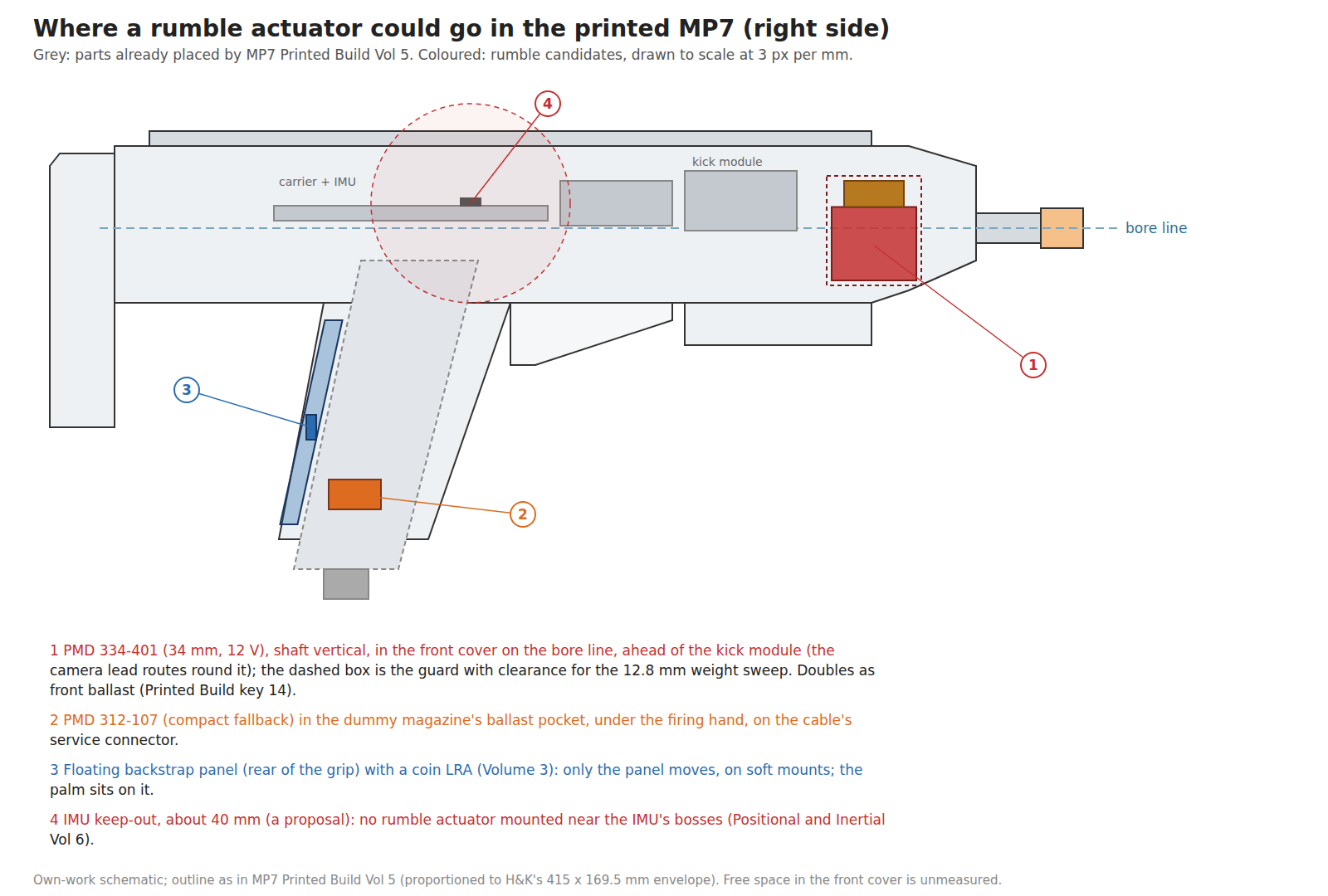
Position 1: the front cover, for the 34 mm motor. The space ahead of the kick module and behind the muzzle is the one region of the receiver that the printed build’s layout leaves free of electronics: the real gun’s barrel is replaced by a camera tube at the muzzle, and the camera lead runs along one side or under the top rail (MP7 Printed Build Vol 5, §5.9). It is also where the printed build already allows “ballast in the front cover, if the balance needs it”, and the printed gun is estimated at 0.9 to 1.3 kg against the real gun’s 2.05 kg (Vol 7). A 75 g motor there is ballast that works. The fit is the risk: the motor is 34 mm across and the receiver is 42 mm wide by H&K’s figure, leaving about 1.6 mm a side inside 2.4 mm walls, and the front cover’s free volume in the hollowed starter file has not been measured. The support hand on the folded-down foregrip is directly below.
Position 2: the dummy magazine, for the compact motor. The magazine is designed rather than sacrificed in a printed gun and has a ballast pocket low down, under the firing hand (Printed Build key 13). A 12 mm motor fits a double-column 4.6 × 30 magazine body easily, its leads join the cable at the magazine’s service connector, and it shakes the part of the gun the firing hand holds. On a VBUS stage it needs no wiring from the 24 V side.
Position 3: a floating backstrap panel, for an LRA. The MP7’s magazine passes through its pistol grip, so the grip has no free interior; but its rear strap, under the palm, can be a separate printed panel carried on soft mounts, with a coin LRA bonded to its inside face. Only the panel moves (Volume 3). It changes the grip’s construction and is the last of the three to try.
Not near the IMU. The carrier’s IMU must be “rigid to the receiver” (Positional and Inertial Vol 6, as quoted by MP7 Printed Build Vol 5), and nothing in this dive should vibrate its bosses directly. About 40 mm is proposed as a keep-out; it is a number to adjust after measurement (6.4).
Orientation. The hand’s thresholds on a gripped handle are “broadly similar” in all three axes (Volume 1), so the shaft’s direction matters less for feel than for side effects. With the shaft vertical, the rotating force lies in the horizontal plane: fore-and-aft (along the recoil axis, which reads as a buzz in the shoulder) and side to side. With the shaft along the bore, it lies in the vertical plane and rocks the muzzle up and down, which the camera sees (6.4). Vertical is proposed; both can be tried with a printed saddle that takes the motor either way.
6.3 How it is held
For a whole-gun shake, the motor must be coupled rigidly to the shell; anything soft between them forms a spring with the motor’s mass and passes less force at the motor’s frequency the softer it is. The foam sleeves on the PlayStation motors in Volume 1 serve a controller’s comfort and noise, not strength.
- A printed saddle with an M3 strap over the can, screwed to heat-set inserts in the shell (MP7 Printed Build Vol 6 gives the insert sizes), or a clamp ring. Not glue alone: an ERM’s force reverses at over 100 Hz, every second it runs, and an adhesive joint under reversing load in PETG is a fatigue test.
- A guard over the weight. The 334-401’s brass weight is exposed (Volume 2’s photograph). Its 12.8 mm radius sweeps a 25.6 mm circle that must clear the guard by at least 1 to 2 mm at every point, allowing for the shaft’s play, and no lead may pass near it. The guard is part of the saddle.
- Leads strain-relieved at the saddle, twisted as a pair, routed away from the camera lead like the solenoid’s (Reference Electronics Vol 8 rules, restated in Printed Build §5.9). A brushed motor is an electrically noisy load; the 100 nF across its terminals in the reference stage belongs at the motor, not on the board.
- For the LRA panel, the opposite: the actuator bonded rigidly to the panel (pressure-sensitive adhesive is how LRAs are designed to be mounted, as the G1040003D’s test fixture shows), and the panel on soft mounts (silicone grommets or a TPU frame) so that it moves relative to the gun.
6.4 What the shaking does to the IMU and the camera
Rumble is a disturbance to two sensors that the gun aims with.
The IMU. A MEMS gyroscope senses rotation from a vibrating proof mass (Positional and Inertial Vol 3), and strong external vibration near its operating frequencies, or rectified into a bias, shows up as false rotation. The rumble motor’s frequency is known (it is commanded), its timing is known (the firmware starts and stops it), and both are logged. Three mitigations, in order of cost: keep the motor away from the IMU (6.2); have the fork gate or down-weight the gyro in the fusion while the rumble runs, as it would during a kick; or notch-filter the gyro at the rumble frequency. Which is needed is a bench question for Volume 7.
The camera. At 113 Hz and about 4 G peak on a 1.3 kg gun (Volume 2), the translational displacement is tiny: 41 m/s² over (2π × 113 Hz)² is about 0.08 mm. Rotation matters more, because a camera at the muzzle that rocks by a fraction of a degree moves the aim point by millimetres on a screen two metres away, and the camera’s frame rate samples the rocking. Whether it shows as cursor jitter during rumble depends on the shell’s stiffness and the motor’s position, and is measured in Volume 7. If it does, the vertical-shaft orientation of 6.2 and the motor’s distance from the muzzle are the levers.
6.5 Noise
The parts’ datasheets give 50 to 65 dB(A) “typical maximum mechanical noise”, without a stated distance (Volume 2). In a gun, three things add to it:
- The shell radiates. A hollow PETG receiver is a sounding board at 100 Hz and its harmonics. Ribs, a stiff saddle and a mass close to the motor reduce it.
- Rattles. Every loose part (a stock rail in its channel, the moving mass in the kick module, a lead touching the shell) buzzes when the motor runs. The printed build’s “nothing loose, nothing that rattles against the moving mass” (Vol 7) is also the rumble’s rule.
- PWM whine at OpenFIRE’s 1 kHz, which the fork removes (Volume 4).
A rumble is much quieter than the solenoid’s kick, which a review of the Sinden found “so strong it often drowns out the game audio” (Controls and Inputs Vol 7). That is the point of Rumble FF for quiet play.
6.6 Power: the USB port
A motor on VBUS (stage A of Volume 4) shares the USB port with the Pico, the camera, the NeoPixel and the OLED. Power Supplies Vol 3 gives the budgets: 500 mA on a USB 2.0 port after configuration, 900 mA on USB 3.x, 100 mA before configuration; Vol 1 estimates the electronics at about 150 mA.
For the compact 312-107 on VBUS, PWM-capped at 70 % (3.5 V average):
Table 1 — For the compact 312-107 on VBUS, PWM-capped at 70 % (3.5 V average)
| State | Current from VBUS (estimate) | With the electronics |
|---|---|---|
| Running | about 0.7 × 0.25 A ≈ 0.18 A (the motor’s 250 mA at 3 V, times the duty) | ≈ 0.33 A: inside a USB 2.0 port |
| Starting, duty stepped | up to 5 V / 5.9 Ω ≈ 0.85 A during each on-time, for tens of ms | ≈ 1.0 A peak: over a USB 2.0 port’s 500 mA |
| Starting, duty ramped over 30 ms | lower; to be measured | the point of the ramp |
The start is the problem, and the reference board already has it as its first rumble measurement (Reference Electronics Vol 7, stage 3). The figures above are estimates from the datasheet; the measurement replaces them.
A coin motor (60 to 100 mA) is no problem on VBUS. The 34 mm motor does not go on VBUS at all.
6.7 Power: the 24 V rail and the one-stage rule
The 334-401 on its own DRV8251A stage (Volume 4) draws from the recoil brick. Decision D16 says the recoil and ejection-port stages “never fire at the same instant”, so that the brick can be sized for one stage: the GST60A24 class, rated 2.5 A, whose over-current trip band starts at about 2.63 A, with the recoil stage regulated at no more than 2.4 A (Power Supplies Vol 2, Vol 4 and Vol 6; decision rows PS-3 revised and P-RE21). That leaves about 0.2 A of headroom while a recoil pulse is on.
With drive-brake PWM, the current the bridge takes from the rail is roughly the duty times the motor current (in the brake interval the motor’s current circulates in the low-side switches and is not drawn from the rail):
Table 2 — With drive-brake PWM, the current the bridge takes from the rail is roughly the duty times the motor current (in the brake interval the motor's current circulates in the low-side switches and is not drawn from the rail)
| Rumble state | Motor current | From the 24 V rail (estimate) | During a recoil pulse (2.4 A) |
|---|---|---|---|
| Running at 12 V average (50 % duty) | ≈ 0.18 A | ≈ 0.09 A | ≈ 2.49 A: under the 2.63 A trip band |
| Starting, trip at 0.5 A, duty at the 60 % cap | up to 0.5 A | up to ≈ 0.3 A | ≈ 2.7 A: inside the trip band |
So the rule for rumble is narrower than D16’s rule for the two power stages: a running rumble may continue through a recoil pulse, but a rumble may not start during one. The fork defers any rumble start (or step up in strength) until SOL_CMD and EJECT_CMD have both been low for the stage’s decay time, which is the same timing the port interlock already uses (P-RE21). This is proposed row MR-6.
Why firmware only, when D16 has a hardware interlock (the Q4 transistor of P-RE21)? Because the failure is different. Two power stages firing together could exceed the brick and stress both coils; a rumble start overlapping a pulse costs, at worst, a brick trip and hiccup, which is the “gun resets when firing” symptom Power Supplies Vol 5 diagnoses, and no damage. Gating the rumble stage in hardware is also awkward: with IN1 tied high (Volume 4), forcing IN2 low would drive the motor, and gating IN1 low with IN2 high would reverse it.
The carrier’s 1,000 µF bulk capacitor (Power Supplies Vol 4) supplies short overlaps in any case; the margin above is the steady-state check.
6.8 Firmware
The firmware’s rumble settings are OpenFIRE’s (Open-Source Firmware Vol 5, §5.8) and its serial force-feedback commands (Vol 6). The private fork (decision D10) needs these changes for the hardware above, collected here as one list for Our Firmware:
- PWM at 20 to 25 kHz on the rumble pin (Volume 4, MR-4).
- Duty cap per motor: 70 % for a 3 V motor on 5 V; 60 % of a 24 V rail (14.4 V) for the 334-401.
- Overdrive and brake envelope for each event: the cap for the first 20 to 30 ms, the running duty after, brake at the end (stage C does it by commanding 0; stage A can only coast).
- Inverted output on GP17 for stage C, so that logical 0 is brake (Volume 4).
- Rumble start deferred while SOL_CMD or EJECT_CMD is high or decaying (MR-6).
- Event lengths fitted to the motor. OpenFIRE’s Rumble FF runs half the rumble length per shot, 75 ms at the default; with braking, a 334-401 can make a distinct pulse in that time, a coin motor cannot (Volume 2). The setting becomes per-motor.
- The gyro gated or weighted down while the rumble runs, if the bench shows it is needed (6.4).
- The LRA channel, if fitted: DRV2605L effects triggered over I²C1, mapped to reload and menu cues (MR-2).
None of these touches the USB HID path or the camera code.
6.9 What rumble adds beside the kick
The brief for this dive asked what rumble adds alongside a solenoid. The answer, from Volumes 1 to 5:
- A second channel. The kick says “you fired”. Rumble says something else (an off-screen reload, damage, a vehicle, a boss) without being confused with a shot. That is how OpenFIRE splits them by default.
- Duration. The solenoid’s vocabulary is single hits. Anything that lasts (an explosion’s rumble, a chain gun spinning up, a helicopter’s rotor) needs an actuator that runs.
- Quiet play. With the solenoid off, Rumble FF gives a per-shot cue at a fraction of the noise, provided the motor can start and stop within a shot (Volume 2).
- Autofire texture at lower solenoid duty. The solenoid’s heat and the brick’s budget limit sustained autofire (Solenoid Recoil Vol 4; Power Supplies Vol 3). A continuous rumble under a slower kick reads as a machine gun at less coil duty.
- Ballast with a job. The printed gun is light (Printed Build Vol 7); 75 g in the front cover helps the balance.
- Accessibility. A player who cannot tolerate the kick’s noise or force keeps a felt cue (Controls and Inputs Vol 7).
What it costs: a part, a stage, 75 g, some noise, one more thing to interlock, and a possible disturbance to the IMU.
6.10 The proposed decision rows
Table 3 — The proposed decision rows
| # | Area | Candidates | Pick | Status | Why, and why not the others | Vol |
|---|---|---|---|---|---|---|
| MR-1 | Rumble actuator | Coin ERMs (Adafruit 1201, PMD 310-103/118); small cylindrical (PMD 307-103, 312-004, 312-107); PMD 324-104; PMD 334-401; gamepad spares; LRA; exciters | Bench-rank PMD 334-401 (target), 312-107 (fallback), Adafruit 1201 (baseline), one gamepad spare (reference) | Testing | Only the 334-401 shakes a 1.3 kg gun hard, at 113 Hz in the hand’s best band; coin parts are about 1/100 of its force on the gun; others weak or out of band | 2 |
| MR-2 | Local cue channel | none; LRA on the receiver; LRA on a floating backstrap panel; exciters | LRA on a floating backstrap, DRV2605L on I²C1 (trial on the SparkFun DA7280 board) | Testing (later) | ≤ 10 ms rise and quiet; strong at the palm when only a panel moves; on the receiver it is a tingle; exciters’ resonances are above the band | 3, 4 |
| MR-3 | Driver for the 34 mm motor | AO3400A on VBUS; DRV8837; DRV2605L; a third DRV8251A on 24 V | Third DRV8251A, IN1 high, inverted PWM on IN2 with pull-up, R_IPROPI 4.22 kΩ (≈ 0.5 A) | Proposed | Brake, current cap and 24 V from the board’s existing part on one pin; braked at power-up; others cannot reach 12 V or cannot brake or limit | 4 |
| MR-4 | Rumble PWM frequency | OpenFIRE’s 1 kHz; 20–25 kHz | 20–25 kHz in the fork | Proposed | 1 kHz is audible at any reduced strength | 4 |
| MR-5 | Motor-driven recoil | solenoid; cam and spring; crank | Solenoid stands; cam and spring a later experiment | Rejected for the first build | Same hit for 1/12 to 1/20 of the energy, but latency, sensing, noise and wear; crank gives no sharp hit | 5 |
| MR-6 | Rumble and the one-stage rule (D16) | none; pause rumble during pulses; defer rumble starts during pulses; hardware gate | Defer starts (and strength steps) while SOL_CMD or EJECT_CMD is high or decaying; running rumble may continue | Proposed | Running rumble ≈ 0.09 A fits the 0.2 A headroom; a start (≈ 0.3 A) does not; a hardware gate on this stage would drive or reverse the motor | 6 |
| MR-7 | Where the motor goes | front cover; magazine; backstrap panel; near the carrier | 334-401 in the front cover (shaft vertical, guarded); 312-107 in the magazine; LRA on the backstrap; nothing within about 40 mm of the IMU | Proposed | Front cover is the free volume and wanted ballast; magazine is under the firing hand; the IMU must not be shaken directly | 6 |
6.11 What could not be verified
- The front cover’s free volume in the hollowed starter file, and therefore whether the 34 mm motor fits.
- Every current figure in 6.6 and 6.7: estimates from datasheets; Volume 7 measures them.
- The gyro’s sensitivity to vibration at about 110 Hz in the chosen IMU, and whether the camera’s aim jitters during rumble.
- The magazine body’s inside width, from the swi-sro scan the printed build uses.
Sources
All figures in this volume come from the earlier volumes of this dive and from the linked sibling dives; no new external source is cited here.
Comments (0)