Motors and Rumble · Volume 4
Driving a Haptic Motor — the MOSFET Stage, the PWM Frequency, Haptic Driver ICs and an H-Bridge on the 24 V Rail
What the reference board's one-transistor stage does and does not do, why OpenFIRE's 1 kHz PWM whines, how overdrive and active braking fix an ERM's slow start and stop, what TI's and Renesas' haptic drivers offer and where their limits fall, and a third DRV8251A that runs a 12 V motor from the recoil rail with braking and a current cap
4.1 What a driver has to do
An ERM is a brushed DC motor; an LRA and an exciter are coils. The driver’s jobs, in order of how often hobby circuits skip them:
- Switch the current on and off from a 3.3 V GPIO, with a defined state at power-up and reset.
- Set the strength, by PWM for an ERM, by the AC amplitude for an LRA.
- Clamp the inductive kick at turn-off: a flyback diode across a low-side-switched motor, or the body diodes and brake path of a bridge.
- Start fast: apply more than the rated voltage for the first tens of milliseconds, so the rotor comes up to speed before the cue is over (Volume 2, 2.4).
- Stop fast: short or reverse the winding at the end, so the motor does not coast for 100 to 180 ms.
- Limit the start current, so the supply is not asked for the stall current (Volume 2, 2.5).
- Track the resonance of an LRA.
A single low-side MOSFET does 1 to 3. Jobs 4 to 7 need either firmware cleverness or a bridge.
4.2 The reference board’s stage
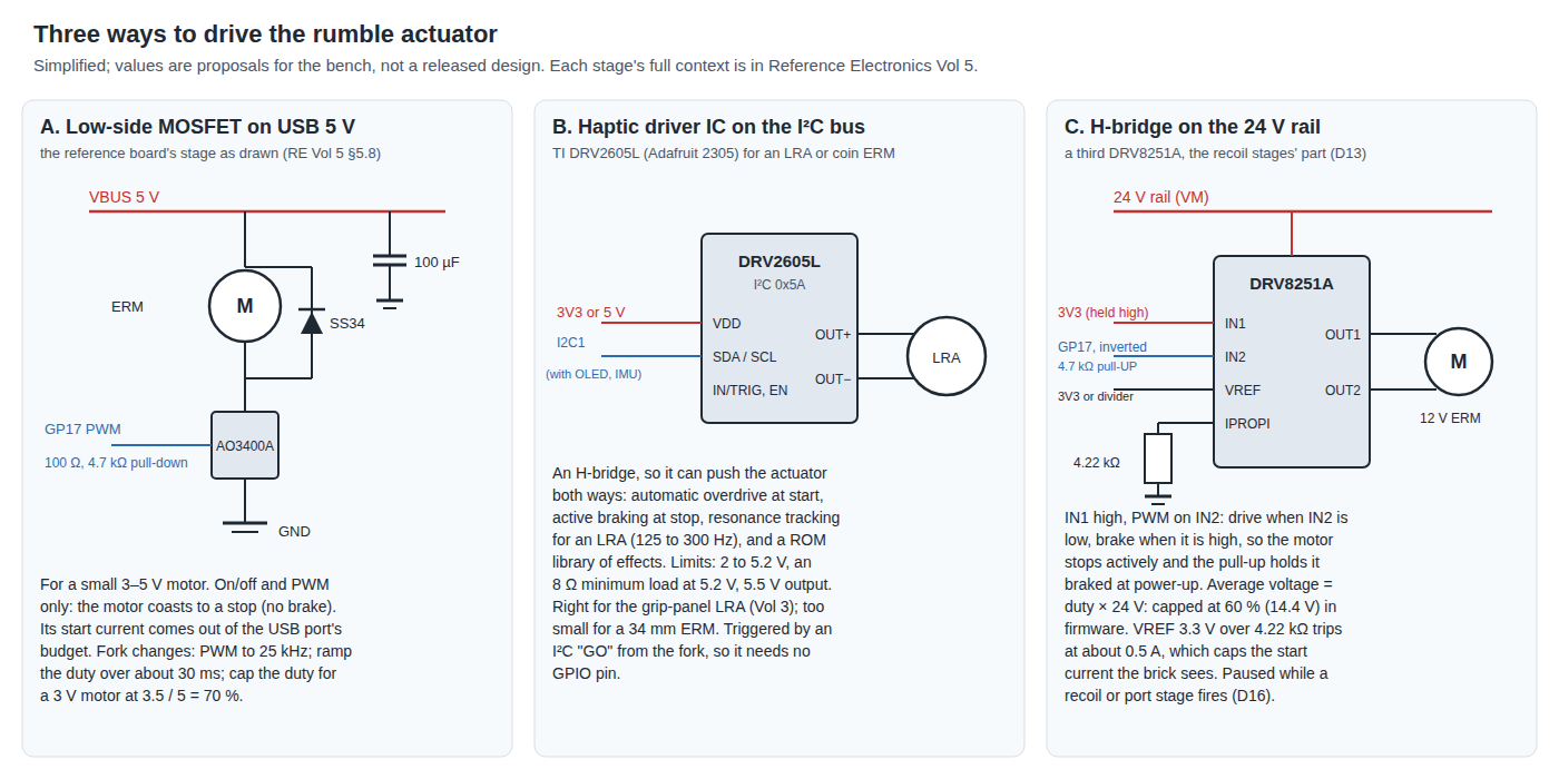
Reference Electronics Vol 5, §5.8, replaces the OpenFIRE Hardware Guide’s 2N2222 with an AOS AO3400A on GP17: 100 Ω gate resistor, 4.7 kΩ pull-down, an SS34 across the motor, 100 nF at the motor terminals and 100 µF on VBUS. That design is not repeated here. Seen from the motor’s side, it has three properties that matter for this dive:
- It can only coast. With the switch off, the motor’s current freewheels through the diode and the rotor spins down on friction. The stop times of Volume 2 apply in full.
- It runs from VBUS. Every milliampere of start current, which is 530 mA for a 312-107 at 3 V and about 850 mA for the same motor put across 5 V (5 V over 5.9 Ω), comes out of the USB port’s budget, shared with the Pico, the camera and the LEDs (Power Supplies Vol 3). The 100 µF supplies only a fraction of a millisecond of it.
- A 3 V motor on 5 V is over-driven continuously at OpenFIRE’s default intensity of 255. Precision Microdrives’ small motors are rated 3 V with a maximum of 3.3 to 3.7 V (Volume 2); continuous 5 V shortens brush life.
All three are fixed in firmware for a small motor, without changing the stage: cap the duty at the motor’s maximum voltage over 5 V (3.5 / 5 = 70 % for a 312-107), and ramp the duty over about 30 ms instead of stepping it, which spreads the start current. The ramp costs some of the start time it is meant to protect, which is why the stage suits only a small motor that starts quickly anyway.
4.3 The PWM frequency
OpenFIRE writes the rumble strength with analogWrite() (Open-Source Firmware Vol 5, §5.8). The Arduino-Pico core’s documentation gives “the default PWM frequency of 1 kHz”, adjustable with analogWriteFreq() from 100 Hz to 1 MHz.1
At 1 kHz a motor whines. The winding’s current ripples at the PWM frequency, the magnetic force on the rotor and the brushes ripples with it, and the motor body radiates a 1 kHz tone and its harmonics, which sits close to the ear’s most sensitive range. At full intensity the pin is simply on, assuming the core’s default 8-bit range in which 255 is 100 % (the core’s documentation gives the supported range, 16 to 65535, but does not state the default), so the default setting is quiet; any reduced intensity whines.
The fix is one line in the fork: set the rumble PWM above the audible band, 20 to 25 kHz. At that frequency the 334-401’s electrical time constant (3.65 mH over 3.5 Ω, about 1 ms) smooths the current almost completely; the coin motors’ much smaller inductances (330–350 µH over about 60 Ω, about 6 µs) do not, so their current is chopped rather than smoothed, which is harmless but means their average current, not their peak, sets the speed. The AO3400A, switched through 100 Ω from a GPIO, has no difficulty at 25 kHz. analogWriteFreq() applies to every pin the sketch drives with analogWrite(), so the fork should check that nothing else depends on 1 kHz; in OpenFIRE v6.2 the solenoid is switched with digitalWrite(), not PWM (Reference Electronics Vol 1).
4.4 Overdrive and braking
The haptic world’s answer to the ERM’s slow start and stop is to drive the motor harder than its rating for a few tens of milliseconds at each end.
- Overdrive. At switch-on, apply a voltage above the rated voltage until the rotor is near its target speed, then drop to the running level. The rotor’s acceleration is set by the torque, which is set by the current, so doubling the voltage during the rise roughly halves the rise time, within the motor’s current and the brushes’ tolerance.
- Active braking. At switch-off, reverse the winding for a few milliseconds (a bridge driving the opposite polarity) or short it (both low-side switches on). Shorting turns the motor into a generator loaded by its own resistance, which stops it in a fraction of the coast-down time; reversing stops it faster still and must be timed to end before the rotor turns backwards.
TI’s DRV2605L does both automatically. Its datasheet’s library table gives, for each of six ERM libraries, a rated voltage, an overdrive voltage, a rise time and a brake time: Library A, for instance, rates 1.3 V, overdrives to 3 V, rises in 40 to 60 ms and brakes in 20 to 40 ms; Library F rates 4.5 V, overdrives to 5 V, rises in 35 to 45 ms and brakes in 10 to 20 ms.2 Precision Microdrives gives the 334-401’s typical “active brake” time as 72 ms, against 176 ms coasting.3
None of it is possible with a single low-side switch, which can apply only one polarity and cannot short the winding. Overdrive alone can be done with one: a motor rated 3 V on a 5 V supply can be driven at 100 % for the first 20 to 30 ms and then dropped to 70 %. Braking needs a bridge.
4.5 Haptic driver ICs
Table 1 — Haptic driver ICs
| IC | Supply | Actuators | Output | What it adds | Package | Limits for this gun |
|---|---|---|---|---|---|---|
| TI DRV2605L | 2–5.2 V | ERM and LRA | differential, 5.5 V maximum; minimum load 8 Ω at VDD 5.2 V | Automatic overdrive and braking (“Smart-Loop”); LRA resonance tracking 125–300 Hz; over 100 licensed Immersion effects in six ERM libraries and one LRA library; audio-to-vibe; PWM, analog, I²C and trigger inputs; thermal and over-current flags | VSSOP-10 (hand-solderable) or 9-ball DSBGA | Fixed I²C address 0x5A; cannot drive a 3.5 Ω 12 V motor; the PMD 312-107 (5.9 Ω) is below the 8 Ω the sheet specifies at 5.2 V |
| TI DRV2625 | 2.7–5.5 V | ERM and LRA | up to 11 V | As the DRV2605L, plus actuator diagnostics by resistance, a battery monitor and a loopable sequencer; “preloaded waveforms” (its sibling DRV2624 takes custom ones) | 9-ball DSBGA only (1.96 mm²) | Needs a reflowed board; nothing gained over the DRV2605L for a cue channel |
| Renesas DA7280 | not stated on the product page | ERM, narrowband and wideband LRA | not stated | Resonance tracking to 300 Hz; wideband LRA drive 25 Hz–1 kHz; waveforms as frequency, time and amplitude triplets | WLCSP-12 or 3 × 3 mm QFN-12 | Ready-made on SparkFun’s ROB-17590 with an LRA fitted ($11.50) |
Sources: TI’s product pages and the DRV2605L datasheet,24 Renesas’ product page,5 SparkFun’s listing.6
The DRV2605L’s datasheet also requires the supply to be between 4 and 4.4 V while its auto-calibration result is written to its one-time memory,2 which matters only if a kit is to ship calibrated; for a prototype, calibration can run at each boot and be kept in RAM.
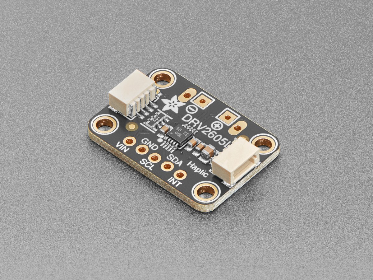
Where it fits. The DRV2605L is exactly right for the grip-panel LRA of Volume 3: a tracking AC drive, a 10 ms start, active braking, and a built-in click library for menu and reload cues. It sits on the carrier’s I²C1 bus with the OLED and the IMU (decisions D36, D37); its fixed address 0x5A is distinct from the usual addresses of an SSD1306-class OLED (0x3C or 0x3D) and an LSM6DSOX (0x6A or 0x6B), which should be confirmed against the actual boards bought. Triggered over I²C by a “GO” bit, it needs no GPIO, which matters because the Pico’s pins are fully allocated with the kit camera (Reference Electronics Vol 2). Adafruit’s breakout, product 2305, costs $7.95.7
4.6 A small H-bridge for a 5 V motor
Between the single MOSFET and a haptic IC sits a plain small H-bridge. TI’s DRV8837 runs a motor from 0 to 11 V (12 V absolute), takes logic from 1.8 to 7 V, delivers 1.8 A (1.9 A peak) through 280 mΩ of total on-resistance, and comes in a 2 by 2 mm WSON-8.8 On VBUS it gives a 5 V motor active braking and overdrive under firmware control, with no current limit and no haptic library. It needs two control pins for brake (IN1 and IN2), or the one-pin trick of 4.7 with a pull-up. It is the right part if the compact 312-107 ends up as the rumble motor on USB power.
4.7 A DRV8251A on the 24 V rail
The 34 mm 12 V motor that Volume 2 found strong enough cannot run from 5 V at anything like its rating, and its 2.7 A typical start current at 12 V would be more than a USB port supplies. It belongs on the 24 V recoil rail (decision D14), behind a driver that limits the current.
The carrier already uses that driver. Reference Electronics Vol 5, §5.12, puts a TI DRV8251A on each recoil stage (decision D13): a 4.5–48 V H-bridge rated 4.1 A peak, 450 mΩ total on-resistance, with current regulation set by a VREF voltage and a resistor on its IPROPI current-mirror output, and no shunt.9 A third copy for the rumble motor keeps the bill of materials to one bridge part, and every feature this dive wants is in its datasheet:
- Brake. The truth table gives IN1 = 1, IN2 = 1 as “Brake; low-side slow decay”, and IN1 = IN2 = 0 as coast, with the device entering sleep after about 1 ms (0.8 to 1.5 ms).9
- PWM. The inputs accept PWM from 0 to 200 kHz, and TI advises that “when using PWM, switching between driving and braking typically works best”, driving with IN1 = 1 and toggling IN2.9
- Current limit. The chop threshold is set by I_TRIP × A_IPROPI = V_VREF / R_IPROPI, with A_IPROPI = 1,575 µA/A; above it, the bridge brakes for a fixed 25 µs off time and drives again.9 With V_VREF = 3.3 V and R_IPROPI = 4.22 kΩ (an E96 value), I_TRIP is about 0.50 A.
The one-pin connection. The Pico’s pins are all allocated; the rumble stage has one, GP17. Proposed: tie IN1 high and drive IN2 from GP17 with the pin’s output inverted (the RP2040’s GPIO output-override can invert a pin in hardware), with a 4.7 kΩ pull-up on IN2. Then a logical duty d gives drive (IN2 low) for d of each period and brake (IN2 high) for the rest, the drive-brake PWM TI recommends; a logical 0 is a continuous brake, so the motor stops actively at the end of every event; and at power-up, reset or with the Pico absent, the pull-up holds IN2 high and the motor braked. A pull-down, as on the recoil stages, would be wrong here: with IN1 tied high, IN2 low means forward, and the motor would run at full voltage whenever the Pico was not driving the pin.
Voltage. The average voltage across the motor is the drive fraction times the rail. The 334-401 is rated 12 V with a 14.4 V maximum, so the fork caps the duty at 60 % (14.4 V on a 24 V rail; more on a rail sagging toward 18 V, so the cap should be computed from the measured rail if the fork reads it). Overdrive is simply a period at the cap before dropping to the running duty.
Start current. With I_TRIP at 0.5 A, the start current the brick sees is about 0.5 A instead of 2.7 A, at the cost of a slower start: the motor accelerates on 0.5 A of torque instead of 2.7 A. Whether 0.5 A still gives an acceptable rise is a bench question (Volume 7); the trip can be raised by lowering R_IPROPI, at the cost of the power budget in Volume 6.
Why not reuse a recoil stage? U4 drives the recoil solenoid and U5 the ejection-port actuator, and the hardware interlock between them (P-RE21) exists because they must never fire together (D16). Hanging the motor on either would tie rumble to a stage that is busy when the gun is firing, which is exactly when rumble is wanted. A third stage is cheap; its interaction with the one-stage rule is in Volume 6.
4.8 The three stages side by side
Table 2 — The three stages side by side
| A. AO3400A on VBUS | B. DRV2605L on I²C | C. DRV8251A on 24 V | |
|---|---|---|---|
| Actuator | Small ERM (coin, 312-107) | LRA, coin ERM | 34 mm 12 V ERM |
| Brake | No (coast) | Yes, automatic | Yes, drive-brake PWM and at stop |
| Overdrive | By firmware duty | Automatic | By firmware duty, within the trip |
| Current limit | None | Over-current flag | I_TRIP set by a resistor |
| Supply drawn | USB port | 3V3 or 5 V | Recoil brick |
| Pins | GP17 | None (I²C) | GP17 |
| On the carrier now | Yes (Q2) | No | No |
4.9 Why this, and why not the others
Criteria: stops crisply; starts within the cue; caps the current the supplies see; drives the chosen actuator within its ratings; costs no extra GPIO; uses parts already on the board where possible.
Table 3 — Why this, and why not the others
| Candidate | For | Against | Decision |
|---|---|---|---|
| DRV8251A, third stage, one-pin drive-brake (C) | Drives the 34 mm motor from the 24 V rail; active brake; current cap from one resistor; same part as U4/U5; one pin; braked at power-up | Adds a stage to the 24 V budget (Volume 6); a fourth copy of a $2-class part; inverted pin needs the fork | Proposed for the 334-401 (MR-3) |
| DRV2605L on I²C1 (B) | Everything an LRA needs; no pin; $7.95 breakout | Not for motors under 8 Ω at 5.2 V or above 5.5 V | Proposed for the grip-panel LRA (MR-2) |
| AO3400A on VBUS (A), as the board has it | Already on the carrier; fine for small motors | Coasts; start current on USB; whine at 1 kHz | Kept for the compact-fallback motor, with the fork’s 25 kHz PWM, duty cap and ramp |
| DRV8837 on VBUS | Brake for a 5 V motor; tiny | 11 V maximum, so not for the 24 V rail; no current limit | Alternative to A if the 312-107 is chosen and braking is wanted |
| DRV2625 | Higher output than the DRV2605L | DSBGA only | Rejected for the prototype |
| DA7280 (SparkFun board) | LRA fitted; wideband capable | Supply and output not on the product page | Bench only, to try an LRA quickly |
| 2N2222 (Hardware Guide) | What OpenFIRE draws | Base current from the GPIO; saturation drop; no advantage over the AO3400A | Rejected (as Reference Electronics did) |
| A relay or a high-side switch | No PWM (relay); no gain (high side) | Rejected |
The fork change common to all three: PWM at 20 to 25 kHz for the rumble pin (MR-4).
4.10 What could not be verified
- The Arduino-Pico core’s default
analogWriterange: not stated on the documentation page read; 8-bit (0–255) is assumed from the Arduino convention and OpenFIRE’s 0–255 setting. - Whether OpenFIRE v6.2 calls
analogWriteFreq()anywhere: the volumes that read its source report onlyanalogWrite(rumblePin, strength). - The DA7280’s supply range and output: not on Renesas’ product page; its datasheet was not read.
- The DRV8251A’s price: Reference Electronics Vol 9 records a search result of about $2.25 at DigiKey, unverified.
- The RP2040’s GPIO output inversion is a documented register feature (IO_BANK0 output override); whether the Arduino-Pico core exposes it directly, or the fork writes the register, was not checked.
Sources
Footnotes
-
Earle F. Philhower III et al., Arduino-Pico documentation, “Analog I/O”. https://arduino-pico.readthedocs.io/en/latest/analog.html, read 2026-10-19. ↩
-
Texas Instruments, DRV2605L data sheet, SLOS854D: Recommended Operating Conditions; Table 1 (ERM library table); auto-calibration and NVM programming; I²C address. https://www.ti.com/lit/ds/symlink/drv2605l.pdf; product page https://www.ti.com/product/DRV2605L, read 2026-10-19. ↩ ↩2 ↩3
-
Precision Microdrives, 334-401 product page. https://www.precisionmicrodrives.com/product/334-401-34mm-vibration-motor-30mm-type, read 2026-10-19. ↩
-
Texas Instruments, DRV2625 product page. https://www.ti.com/product/DRV2625, read 2026-10-19. ↩
-
Renesas, DA7280 product page. https://www.renesas.com/en/products/da7280, read 2026-10-19. ↩
-
SparkFun Electronics, “SparkFun Qwiic Haptic Driver - DA7280”, ROB-17590. https://www.sparkfun.com/sparkfun-qwiic-haptic-driver-da7280.html, read 2026-10-19. ↩
-
Adafruit, “Adafruit DRV2605L Haptic Motor Controller - STEMMA QT / Qwiic”, product 2305. https://www.adafruit.com/product/2305, read 2026-10-19. ↩
-
Texas Instruments, DRV8837 product page. https://www.ti.com/product/DRV8837, read 2026-10-19. ↩
-
Texas Instruments, DRV8251A 4.1-A Brushed DC Motor Driver with Integrated Current Sense and Regulation, SLVSFU6: Recommended Operating Conditions (f_PWM 0–200 kHz), Table 8-2 (H-bridge control), Equation 3 (I_TRIP), t_OFF 25 µs, t_SLEEP, t_WAKE. https://www.ti.com/lit/ds/symlink/drv8251a.pdf; product page https://www.ti.com/product/DRV8251A, read 2026-10-19. ↩ ↩2 ↩3 ↩4
Comments (0)