Motors and Rumble · Volume 7
Measuring It and Keeping It Working — an Accelerometer on the Shell, a Sled Test, and the Wear and Failure of Vibration Motors
The bench procedure with the Analog Discovery Pro ADP3450 that turns Volumes 2 to 6's estimates into measurements: acceleration and frequency at the grip, lag, rise and stop, start and running current, the rail during a kick, the IMU and the aim during rumble, and a blind ranking by hand; then how a motor wears, how it fails, how to diagnose it and how to replace it
7.1 What to measure, and why
Every number in Volumes 2 to 6 that bears on the gun is an estimate: the acceleration a motor gives a 1.3 kg shell, the start current, the headroom on the 24 V rail, the effect on the IMU. The bench replaces them, in this order, because each result feeds the next decision:
Table 1 — Every number in Volumes 2 to 6 that bears on the gun is an estimate: the acceleration a motor gives a 1.3 kg shell, the start current, the headroom on the 24 V rail, the effect on the IMU. The bench replaces them, in this order, because each result feeds the next decision
| Test | Measures | Decides |
|---|---|---|
| 1. Sled | Each motor’s amplitude, frequency, lag, rise and stop on a known mass | Whether the part matches its datasheet; the bench shortlist’s ranking (MR-1) |
| 2. In the gun | Acceleration and frequency at the grip and the fore-end, with each mount and orientation | Position and orientation (MR-7); the duty cap for comfort |
| 3. Current | Start and running current from VBUS and from the 24 V rail; the rail during a kick | The ramp (VBUS); the trip resistor and the deferral rule (MR-3, MR-6) |
| 4. IMU and aim | Gyro output and cursor jitter while the rumble runs | The IMU keep-out and the fork’s gyro gating |
| 5. By hand | A blind ranking by the two builders | Whether the numbers above match the hand |
7.2 The instruments
From the lab (decision D9; lab list in the hub’s shared capability notes):
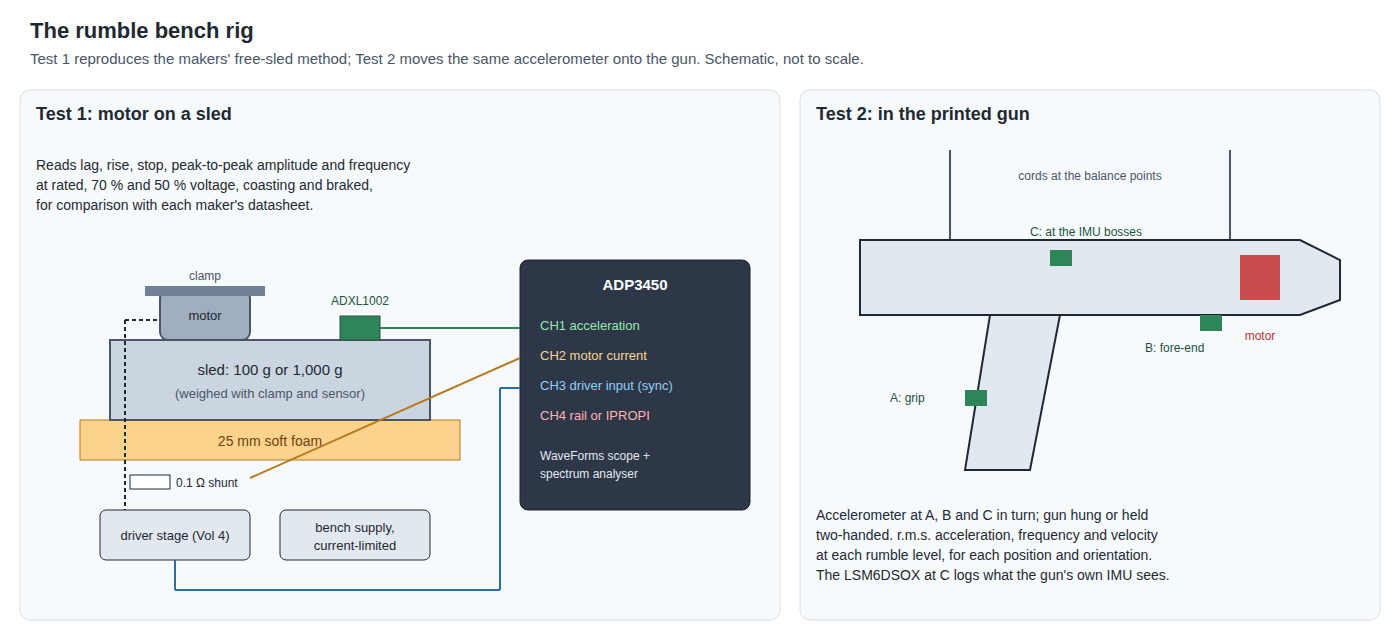
- Digilent Analog Discovery Pro ADP3450: four analogue scope channels, used here for acceleration, current, rail voltage and a sync signal. Its software (WaveForms) includes a spectrum analyser, which gives the vibration frequency directly.
- Programmable bench supplies for the motor’s rail during Test 1, current-limited.
- An analogue accelerometer. Solenoid Recoil Vol 6 chose the Analog Devices ADXL1002 (±50 g, DC to 11 kHz) for impacts, and the same part serves here: rumble is slow by comparison, and ±50 g covers the largest motor on the smallest sled. The rig, the mounting and the reasons are in that volume and are not repeated.
- The IMU itself. Decision D38 buys an Adafruit LSM6DSOX breakout for the inertial dive. Configured as Positional and Inertial Vol 6 proposes (±16 g, 1 kHz output), it samples a 100 to 230 Hz rumble well above twice its frequency, and, mounted where the carrier’s IMU will be, it measures exactly what the gun’s own IMU will see. It is a second channel, not a substitute: the ADXL1002 on the scope keeps everything on one time base.
- A 0.1 Ω low-side shunt for current, as Solenoid Recoil Vol 6 and Reference Electronics Vol 7 use (one single-ended channel).
7.3 Test 1: the sled, to check each motor against its maker
The makers’ method is a free test mass. Jinlong’s LRA sheet describes it: a 100 g “dummy jig” of 15 × 45 × 105 mm “located on Sponge”, the actuator fixed to it, an accelerometer on it measuring along the actuator’s axis (Volume 3). Precision Microdrives uses “standard test sled” masses of 100, 250 and 1,000 g (Volume 2).
Procedure.
- Make two sleds: a 100 g block and a 1,000 g block (aluminium or steel, cut on the lab’s mill; a 3D-printed box filled with steel shot is a fallback). Weigh each with the motor’s clamp and the accelerometer, and record the total.
- Clamp the motor to the sled with its shaft perpendicular to the accelerometer’s axis. Rest the sled on 25 mm of soft foam.
- Power the motor from a bench supply at its rated voltage, switched by the driver stage it will use in the gun (Volume 4).
- On the ADP3450: CH1 accelerometer, CH2 shunt, CH3 driver input (sync). Trigger on CH3.
- Capture 20 starts and stops. Read: lag (sync to first visible oscillation), rise (to the steady amplitude; the makers use “rated amplitude”, Jinlong 50 %), stop (release to rest, or to 10 %), the steady peak-to-peak amplitude in G, and the frequency from the spectrum.
- Repeat at 70 % and 50 % of rated voltage, which gives the speed-squared law of Volume 2 for this unit.
- For stage C (Volume 4) also with the brake: release by commanding brake instead of coast, and read the stop time again.
Read it against the datasheet. A Precision Microdrives motor should land inside its datasheet’s spread: speed within the stated tolerance (±1,350 rpm for the 334-401), amplitude above its minimum (6.7 G on 1 kg for the 334-401). A unit far outside is a bad unit or a bad rig. The gamepad spare, which has no datasheet, gets its numbers here for the first time.
7.4 Test 2: in the gun, at the grip
Procedure.
- Fit the motor in each candidate position (Volume 6): front cover, shaft vertical and shaft along the bore; magazine pocket. Use the real saddle and guard.
- Fix the ADXL1002 to the grip’s side at the palm, then to the fore-end under the support hand, then near the carrier’s IMU bosses.
- Hold the gun in a firm two-handed grip, or, for repeatability, hang it from two cords at its balance points, which approximates the free body of the sled; record both.
- Run each rumble level the firmware will use (the cap, 75 %, 50 %, 25 % of it), 2 s each.
- Read the r.m.s. acceleration and the dominant frequency at each sensor position; compute velocity as a_rms / (2πf).
What it answers. How far the free-body estimate of Volume 2 (about 29 m/s² r.m.s. at full voltage for the 334-401 on 1.3 kg) is from a held, hollow gun; how much the position and orientation matter; what the strength at the grip is at each duty, so that the fork’s levels can be set by feel and checked by number. Griffin’s reference of 5 m/s² r.m.s. at 50 Hz, about 16 mm/s (Volume 1), is a useful marker of “strong”.
7.5 Test 3: current and the supplies
VBUS (stage A, 312-107 or coin). A USB breakout with the shunt in its ground return, as Reference Electronics Vol 7 sets up for its stage 3. Capture the VBUS current through a stepped start and through a 30 ms ramp, at the duty cap. The target is the whole gun inside 500 mA on a USB 2.0 port, the Power Supplies Vol 3 budget.
The 24 V rail (stage C, 334-401). The brick, the carrier’s recoil stage at its regulated set point, and the rumble stage, with: CH1 the brick’s output current, CH2 the rail voltage, CH3 SOL_CMD, CH4 the rumble stage’s IPROPI voltage (which reads the motor current through the DRV8251A’s current mirror at 1,575 µA/A). Capture:
- the rumble alone: start (with the trip at about 0.5 A) and running;
- autofire alone;
- autofire with the rumble running through it (allowed by MR-6);
- a rumble start forced inside a recoil pulse (what MR-6 forbids), to see how close it comes to the brick’s trip band, and whether it trips.
If capture 3 approaches 2.63 A, MR-6 tightens to a pause; if capture 4 does not trip with margin, the deferral could be relaxed. Either way the rule is set by the trace.
The rise at a capped current. Repeat Test 1’s rise measurement for the 334-401 with the DRV8251A’s trip at 0.5 A, 0.8 A and 1.2 A (R_IPROPI 4.22, 2.61, 1.74 kΩ). The rise time against the current cap is the trade the brick budget forces.
7.6 Test 4: the IMU and the aim
- With the LSM6DSOX (or the carrier’s IMU) fixed where the carrier will hold it, log the gyro’s three axes at 1 kHz with the gun still, then with the rumble at its cap, then at half.
- Read the gyro’s apparent rate during rumble: its oscillating part at the motor frequency, and any offset (a rectified bias), which is the dangerous part because it integrates into drift.
- With the camera running against the screen’s emitters at 2 m, log the cursor position with the gun on a rest, rumble off and on. Read the jitter in pixels.
The results set the IMU keep-out (Volume 6, MR-7) and whether the fork needs to gate the gyro during rumble.
7.7 Test 5: by hand, blind
Numbers do not settle what feels right. With the gun’s shell closed, and the motors switched by someone else in random order, the two builders, Michael and his father, each rank each motor and level on three questions: is it clearly felt at the grip; does it feel like “the gun” or “a buzzer in the gun”; is it unpleasant after 10 s. Record the rankings beside Test 2’s numbers.
7.8 How a vibration motor wears
An ERM is a brushed DC motor working in one of the harshest regimes a small motor sees: frequent starts at stall current, and a heavy out-of-balance load on its bearings.
- Brushes and commutator. Every start draws the stall current through the brushes; arcing at commutation erodes them. Running above rated voltage, a common hobby habit (a 3 V motor on 5 V), increases both. Precious-metal brushes are for low current; carbon brushes for higher current and longer life (Volume 2). Sega’s Alien3 gun manual has a procedure for replacing its motor’s brushes (Arcade Light Guns Vol 5).
- Bearings. The eccentric load is a rotating radial force on the bearings for every second of running: about 58 N at 113 Hz for the 334-401 (Volume 2), on ball bearings; sintered bronze in the small motors.
- The weight’s fixing. A weight pressed or glued on a shaft can work loose; a loose weight changes the vibration and can contact the guard.
- Mounts and saddles. Printed saddles and inserts take the same reversing load as the motor’s bearings; screws loosen and PETG creeps.
- Leads. Flying leads on a vibrating motor fatigue at the point where they leave the can, unless strain-relieved there.
- LRAs have no brushes; the Jinlong sheet’s life test is 1,000,000 cycles of 2 s on and 1 s off (Volume 3). The spring and the adhesive bond are what wears.
For scale, Precision Microdrives’ longevity test gives an MTTF of 1,780 h for the coreless 307-103 and 132.9 h for the 310-103 coin motor, under a 2 s on, 2 s off cycle at rated voltage, with the maker’s warning that the figure is not a guaranteed lifetime (Volume 2). Cue-style rumble of 150 ms events uses that up very slowly; continuous game-driven rumble, overdrive and over-voltage use it faster.
7.9 Failures, diagnosis and repair
Table 2 — Failures, diagnosis and repair
| Symptom | Likely cause | Check | Fix |
|---|---|---|---|
| No rumble at all | Rumble disabled in the App or by a mapped Rumble Switch; firmware fault; open lead; dead driver; seized motor | App’s Gun Tests rumble button (Open-Source Firmware Vol 4); voltage at the motor terminals on the scope; motor resistance with the leads off (3.5 Ω for a 334-401, 5.9 Ω for a 312-107) | Re-enable; re-crimp or resolder the lead; replace the MOSFET or the DRV8251A; replace the motor |
| Rumble weak or slow to start | Worn brushes; supply sag; duty cap or ramp set too low; weight loose | Compare Test 1’s lag, rise and amplitude with the unit’s first measurement | Replace the motor; correct the setting; re-fix the weight |
| Starts only with a tap, or at some shaft positions | Brush or commutator dead spot | Resistance while turning the shaft slowly by hand | Replace the motor |
| Whine at reduced strength | PWM at 1 kHz | Scope the drive frequency | Fork change MR-4 |
| Rattle or buzz at certain levels | Loose saddle, guard, a lead or another part in the shell resonating | Run a slow sweep of duty and listen; touch parts to find it | Tighten; add a rib or a felt pad; secure leads |
| Gun resets or brick hiccups when rumble starts | Start current on USB, or on the 24 V rail during a pulse | Test 3 captures | Ramp (VBUS); MR-6 deferral; lower trip current |
| Cursor drifts or jitters during rumble | Gyro bias from vibration, or camera rocking | Test 4 | Move the motor; gate the gyro in the fork; change orientation |
| Motor hot | Running above rated voltage; stall (weight fouling the guard) | Feel; scope the current for a stall-level steady current | Correct the cap; clear the guard |
What can be repaired at the bench. Leads, connectors, saddles, guards, firmware settings, driver ICs (with the lab’s rework station). What cannot, practically. The motor itself: small vibration motors are sealed and sold as replaceable parts; Sega replaced brushes in an arcade motor, but the motors in this dive are not built for it.
Parts availability. The Adafruit coin motor is a stock item (Volume 2). Precision Microdrives describes the 334-401 as a “stocked design” with samples through its online store, price by enquiry; buy spares with the first order. The DRV8251A is the carrier’s own part.
7.10 Maintenance
There is little to do, and it is inspection rather than service:
- Every time the shell is opened: check the saddle screws and inserts for looseness, the guard for witness marks from the weight, the leads at the can for cracked insulation.
- After any change of firmware settings: re-run the App’s rumble test and listen for whine or rattle.
- If the rumble’s feel changes: repeat Test 1 on the motor and compare with its first record. A motor whose lag or rise has doubled, or whose amplitude has fallen by a third, is worn; replace it rather than raise the duty, which wears it faster.
- Keep the first-measurement record of each motor (Test 1), with the date. It is the only baseline a wear judgement can be made against.
7.11 What could not be verified
- The LSM6DSOX’s maximum output rate from ST’s own datasheet: not read; the 1 kHz configuration of Positional and Inertial Vol 6 is used, which is sufficient for a 230 Hz rumble.
- Brush-replacement practicality for any motor in this dive: none of the datasheets offers it.
- Every expected value in this volume comes from the estimates of Volumes 2 to 6.
Sources
All procedures here are built from the earlier volumes and the linked sibling dives (Solenoid Recoil Vol 6 for the accelerometer and rig; Reference Electronics Vol 7 for the USB current capture; Positional and Inertial Vol 6 for the IMU configuration). The makers’ test methods are quoted in Volumes 2 and 3 with their sources.
Comments (0)