Power Supplies · Volume 6
Recommendations by Build Stage, and the Bench Tests That Replace Guesses
What to power the bench prototype, the wired MP7 donor and the later one-cable guns with, and nine measurements on the lab's supplies and Analog Discovery that turn this dive's assumptions into numbers
6.1 Three Stages, Three Answers
Jeff and his son Michael are building a light gun now, starting small and working up: a bench prototype, then a first gun built into an airsoft MP7 donor, and later guns that may run from one cable or from a battery. Each stage wants a different answer to the power question, and the previous five volumes give enough to choose. This volume makes the choices and sets out the measurements that should replace this dive’s planning figures with real ones. Nothing here has been built or measured yet; every bench result is a slot waiting to be filled.
6.2 Stage 1: The Bench Prototype
Recommendation: no brick at all. Use the lab’s programmable supplies.
On the bench, the solenoid’s supply should be an instrument, not a product. A programmable supply sets voltage and current limit independently, reads back current, and does not hiccup; the lab also has a 50 A linear supply that will hold its voltage through any pulse a light-gun coil can draw.1 That makes the coil’s own behaviour visible, separately from any brick’s quirks, which is the whole point of a prototype.
The lab’s programmable supplies are several units, one controlled over Bluetooth and the rest over USB; their models are not recorded here, so their current-limit resolution and readback rate are not known and should be read from their own manuals before T2 and T3. The USB-controlled units are the natural choice for anything scripted, such as a sweep of rail voltage from 12 to 28 V for the coil comparison, because they can be driven from the same PC that runs WaveForms and the Pico; the Bluetooth unit suits a supply that has to sit away from the PC, for instance feeding the second power stage. A supply’s readback is an average; the pulse itself is captured on the Analog Discovery Pro, as below.
Set up:
- Coil supply: a programmable bench supply at the coil’s intended voltage, current limit set a little above V/R so that a stuck-on MOSFET is limited (the bench version of Ultimarc’s reliance on the brick’s limit, made deliberate). Leads short and twisted.
- Logic: the Pico from a PC’s USB port, as it will be in use, so that the USB side of grounding is real from the start.
- Driver: the low-side MOSFET with flyback diode and gate pull-down, laid out with the single ground join of Vol 5. The circuit is the Reference Electronics dive’s.
- Instrumentation: a low-value current shunt in the coil’s return, at the ground join, so its voltage is referenced to the gun’s ground; the Analog Discovery Pro ADP3450 plugged into the same PC as the Pico. How the current is captured is set out in the next section.
6.2.1 Capturing current on the ADP3450
The ADP3450 has four oscilloscope channels, single-ended, BNC, with at least 55 MHz bandwidth, 14-bit resolution, up to 125 MS/s on every channel simultaneously, and a ±25 V input range with respect to ground; it also has 16 digital channels at LVCMOS 1.2 to 3.3 V, 5 V tolerant.2 It has no current input, and its inputs are not differential. Current is therefore captured as the voltage across a shunt:
- Low-side shunt at the ground join, one channel. Both ends of the shunt sit near the gun’s ground, so one channel on its most sensitive range (0.125 mV absolute resolution at 200 mV/div and below)2 reads it directly. A 0.1 Ω metal-strip shunt on the bench rig gives 200 mV at 2 A, about 1.25 mA per step; this is the choice the Solenoid Recoil dive made for its rig. On the Reference Electronics carrier, the 10 mΩ sense resistor in each MOSFET source does the same job at 20 mV for 2 A, about 12.5 mA per step, which is enough for a pulse shape.
- Not a high-side shunt. Measuring across a shunt in the 24 V lead needs two channels and a difference, each channel on the high range where it sees the whole rail; the small difference is then resolved far more coarsely. Use it only if the return cannot be broken.
- Rail voltage above 25 V needs a ×10 probe. The Solenoid Recoil dive’s working window reaches 28 V, and a drain at turn-off reaches the clamp voltage, so the rail and drain channels take ×10 probes; the shunt channel does not.
- One reference. The instrument’s BNC shells are tied to its own ground and so, through USB, to the PC. Plugging it into the same PC as the Pico keeps a single reference (Vol 5).
- Linux mode. The ADP3450 can run in a stand-alone Linux mode, where Digilent’s specification limits the buffer to 32,768 samples.2 A 45 ms pulse at 1 MS/s is 45,000 samples, more than that buffer; either capture from WaveForms on the PC, or drop to 500 kS/s, which still resolves a coil current that changes over milliseconds.
- Its own supply. The instrument runs from its own 19 V adapter (45 W maximum).2 Its one programmable digital supply (1.2 to 3.3 V, 300 mA) is for logic, not for a coil.
What Stage 1 should produce is the list of numbers in section 6.8. With them, the choice of brick for Stage 2 is arithmetic.
6.3 Stage 2: The Wired MP7 Donor
Recommendation: architecture A, a floating desktop brick sized so the pulse current sits below the bottom of its trip band, on its own DC pair to the gun. The rail is decided: 24 V class, 18–28 V working, current regulated from the first driver board (D13, D14), and the recoil and ejection-port stages never fire at the same instant (D16). The brick is therefore sized for one stage: the GST60A24 class (Vol 2, section 2.11). There is no USB-only stage in between (D17): the build goes from the bench supplies of Stage 1 straight to this brick.
The MP7 Donor Build is the first gun that leaves the bench, and it should be the least ambitious electrically. Architecture A is what every commercial gun except Sinden uses, it has the fewest parts, and its failure modes are all understood. Specifically:
- Brick. From the table in Vol 2, chosen on the measured coil current. The GST60A24-P1J (24 V, 2.5 A, floating output, 5.5 × 2.1 mm plug, $24.86 at TRC Electronics or $19.40 at DigiKey on 2026-10-18),34 which covers one regulated stage up to about 2.4 A. If the coil chosen on the bench must be regulated above that, the GST90A24 (2.4 to 3.7 A, ordered with the 2.1 mm plug). The NSP-75-24, once the answer for two stages firing together, is not needed: the firmware interlocks the two outputs (D16).
- Connector at the gun. One GX16 (or GX12) in the magazine base plate carrying USB and the 24 V rail together (D31, 19 October 2026; MP7 Donor Build Vol 2). It is not hot-pluggable, so the order is fixed: mate the GX first, then plug the brick into the wall; unplug the brick from the wall before turning the ring. That order also means the DC rail comes up on the brick’s own start-up ramp rather than on a plug being pushed home, which is gentler on the regulated driver’s 2 V/µs limit on supply slew (Reference Electronics Vol 5). The solenoid return has its own pin, apart from USB ground. The brick’s 5.5 × 2.1 mm plug meets the cable at its far end. The PJ-005A, the previous pick, is kept in Vol 2 as the record of why it lost.5
- Cable. The solenoid supply on its own pair, 22 AWG or heavier for a 3 m run at 2 A, twisted. USB on its own conductors. The two run side by side in one sleeve to the GX at the base plate and split at the far end.
- In the gun. The Reference Electronics board’s reservoir at the DC entry (35 V is enough behind a GST brick, Vol 4); an SMBJ28A across the input (D33) (Vol 5); a time-lag cartridge or SMD fuse, valued from the fuse maker’s I²t curves once T1 has measured the peak current of each stage (they never fire together, D16); reverse-polarity protection at the entry; and the single ground join at the MOSFET source.
- Firmware. OpenFIRE’s defaults (45 ms on, 80 ms off) to begin with; optional temperature sensing on the coil using OpenFIRE’s TMP36 support, whose default warning and shut-off are 38 °C and 45 °C.6
6.4 Stage 3: One Cable, or None
Later guns may drop the second cable. The options, and where each is developed:
- USB-only (architecture C). One cable, a current-limited boost, a bank and a firmware that fades gracefully. Vol 3 and Vol 4 set out what it can do: a few full-strength shots per burst from a USB 2.0 port, sustained autofire only with a small coil on a Type-C 3 A source. The complete system belongs in the Fully Wired dive.
- USB-C Power Delivery. A PD sink negotiating 15 or 20 V removes most of USB’s power limit and, with it, most of the case for storage. USB-C Power Delivery.
- A battery in the gun. A LiPo can supply a solenoid pulse directly or through a boost, and can be charged slowly from USB between sessions; it also makes a wireless gun possible. LiPo Batteries, Wireless Power Only and Fully Wireless.
These dives are planned and not yet written. This one gives them their arithmetic: E / P for sustained rate, ½C(V₁² − V₂²) for burst depth, and the grounding rules, which apply unchanged.
6.5 The Recommendation Matrix
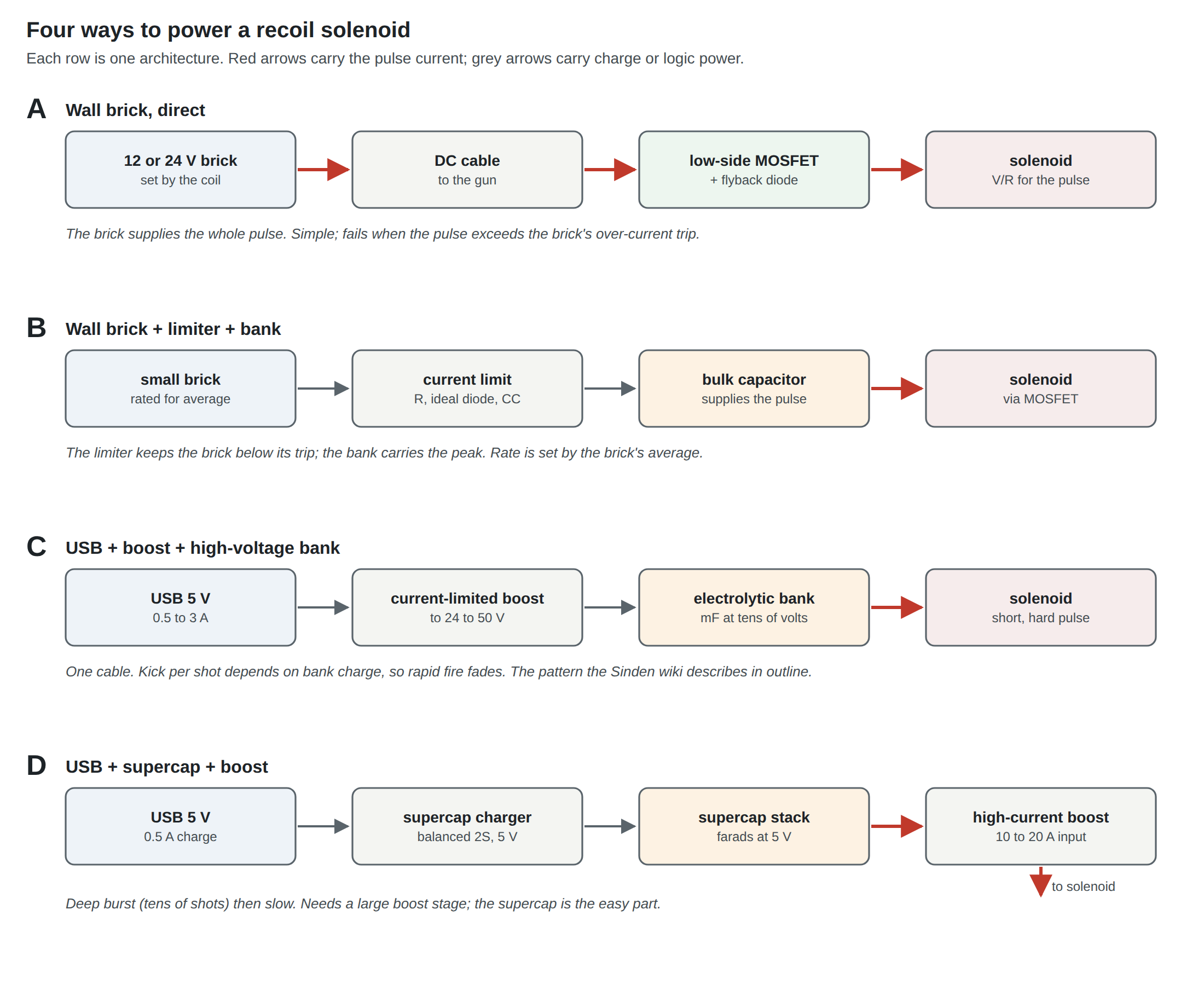
Table 1 — The Recommendation Matrix
| Stage 1: bench prototype | Stage 2: wired MP7 donor | Stage 3a: USB-only (later dives; no prototype stage, D17) | Stage 3b: PD or battery | |
|---|---|---|---|---|
| Architecture | A, on a lab supply | A | C (or D) | own dives |
| Coil supply | programmable bench supply, current-limited; 50 A linear as reference | floating 24 V desktop brick sized for one stage (D14, D16), pulse below the bottom of its trip band | USB through a current-limited front end and boost to a bank | PD sink or LiPo |
| Typical choice | lab programmable supplies (USB-controlled for scripted sweeps) | GST60A24-P1J (one regulated stage ≤ 2.4 A); GST90A24 only for a coil regulated above 2.4 A | TPS2553 + TPS55340 + electrolytic bank (Vol 3) | see linked dives |
| Connector | bench leads | one GX16/GX12 in the base plate for USB and 24 V, mated unpowered (D31); JST VH inside | USB only; XT30 inside to the bank | USB-C; XT30 inside |
| Storage | none needed | local reservoir only | bank sized for burst depth (Vol 4) | battery is the store |
| Protection | supply current limit | time-lag fuse, SMBJ28A, reverse-polarity stage, gate pull-down | load switch, bank bleeder, firmware pulse scaling | per linked dives |
| Grounding | single join at MOSFET source; instrument on the same PC | single join; floating brick; separate DC pair | single join; bank return local | single join |
| What it proves | the coil’s numbers | the gun, as a product | one-cable feasibility | the end state |
6.6 Why This, and Why Not the Others
Every cell of the matrix is a choice. The ones that are not obvious, with what lost and why:
Table 2 — Every cell of the matrix is a choice. The ones that are not obvious, with what lost and why
| Choice | Pick | Rejected, and why |
|---|---|---|
| Stage 1 coil supply | The lab’s programmable supplies, current-limited, with the 50 A linear as a reference | A brick: hides the coil’s behaviour behind its own trip band and hiccup, and one brick cannot sweep 12 to 28 V for the coil comparison. A capacitor bank: adds a second unknown before the first is measured |
| Stage 2 architecture | A, brick direct | B (brick, limiter, bank): only needed if the chosen coil’s pulse exceeds every reasonable brick, which Stage 1 will show. C (USB only): sustains full strength only with a 12 V, 1 A class coil on a 3 A Type-C port (Vol 3). D (supercap and boost): the hardest block in the dive, for a gun that is wired anyway |
| Stage 2 brick | Mean Well GST60A24 class (D14, D16); GST90A24 as the step up | NSP-75-24: needed only for two stages at once, which D16 forbids; open-frame cabinet part; its 28–36 V over-voltage band would force 50 V capacitors. Unbranded bricks, the earthed GST120A, laptop bricks and linear bricks, for the reasons in Vol 2, section 2.12 |
| Stage 2 cabling | USB and DC as separate conductors, one sleeve, one GX at the base plate (D31) | One conductor set with a shared ground: puts the pulse return on the USB ground, the fault of Vol 5; the solenoid return keeps its own pin. Two separate leads and two holes: the arrangement before D31, given up for one locking plug. USB-only: see C above |
| Gun-side connector | One GX16 (or GX12) for USB and 24 V (D31) | Same Sky PJ-005A, the previous pick: safe to unplug live and fits the brick’s plug, but a second hole and a second lead beside USB, and it does not lock. PJ-002A (2.5 A). XT30 (no brick has one, power only). Vol 2, section 2.12 |
| Input fuse | Time-lag fuse, cartridge or SMD, from the maker’s I²t curves | A fast fuse opens on the pulse; a resettable PTC fuse trips slowly and at a multiple of its hold current, so it is a poor match for a pulse that must pass and a stuck-on coil that must not. No fuse: a stuck MOSFET on a 5 A brick dissipates the coil’s full V²/R (Vol 2, section 2.9) |
| Reverse polarity | A P-channel MOSFET in the supply lead, part chosen in the Reference Electronics dive | A series Schottky drops its forward voltage at the pulse current on every shot and heats; a shunt diode with the fuse turns every reversed plug into a blown fuse, a poor experience in a kit. 5.5 mm bricks are not all centre-positive, so the risk is real |
| Input TVS | SMBJ28A (D33) | SMBJ33A: covers the window with more stand-off margin, but its 53.3 V clamp at rated current is above the DRV8251A’s 50 V absolute maximum. SMBJ26A: would need the working window narrowed to 26 V. Vol 5, section 5.6 |
| Stage 3 | Deferred to the Power Delivery, battery and Fully Wired dives | A choice now would be made before Stage 1 has measured the coil |
| A USB-only prototype between Stages 1 and 2 | None (D17) | USB alone cannot sustain full-strength autofire (Vol 3); a prototype that fades would test the wrong thing |
6.7 Bench Tests: What to Measure and How
Each test replaces an assumption in this dive with a measurement. The instruments are those listed for the lab: the Analog Discovery Pro ADP3450 and Analog Discovery 2, the 50 A linear supply and the programmable supplies (one Bluetooth-controlled, the rest USB-controlled), DMMs, and the FNIRSI tool set.1 Current is always a shunt voltage on the ADP3450 (section 6.2); averages can be cross-checked against a programmable supply’s readback.
6.7.1 T1. Coil resistance and the real pulse current
Four-wire resistance of the coil at room temperature, then again after a minute of autofire. Coil resistance rises with temperature (copper’s coefficient is about 0.4 % per °C), so a hot coil draws less current and kicks less. Then capture coil current through the shunt for one 45 ms pulse at the intended voltage. The trace shows the L/R rise, the dip as the plunger moves, and the settled V/R: the real shape behind Vol 1’s resistive approximation. Energy per shot is the integral of V × I over the pulse, which WaveForms can compute.
6.7.2 T2. The brick’s real pulse behaviour
Load the chosen brick with 45 ms pulses at increasing current: a coil and series resistors, or a resistor bank switched by the MOSFET. Capture output voltage (×10 probe, since a 24 V brick’s overshoot can pass the instrument’s ±25 V direct range) and current (low-side shunt in the load’s return, one channel). Find the current at which it first hiccups and measure the retry period. This fills the two gaps in Mean Well’s datasheet that matter most, detection time and retry period, for the actual unit.
6.7.3 T3. Two bricks of the same type
Repeat T2 on a second unit of the same model. The trip band is 105 to 150 % of rating; two units may sit at different ends of it.3 If one gun has to work on any brick of the type, design to the worse of the two, and to the bottom of the published band.
6.7.4 T4. Cable and connector drop
Scope coil voltage at the coil terminals and at the brick’s plug during a pulse, with the gun’s real cable. The difference is the cable and connector loss; compare with Vol 2’s table.
6.7.5 T5. Ground shift between gun and host
The test of Vol 5: the difference between the Pico’s ground and the host’s USB shell during a pulse, measured on the same PC as the gun, with the ADP3450 channel on its most sensitive range. Tens of millivolts is good; volts means the pulse is returning through the USB ground.
6.7.6 T6. The logic’s own current
The Pico, camera and LEDs from a USB inline meter, idle and tracking. The camera is now likely to be a harvested Wii Remote camera on a carrier, which the Reference Electronics dive proposes because the SEN0158 is no longer buyable from DFRobot; neither has a published supply current. Fills the camera current DFRobot does not publish, and replaces the 0.75 W planning figure used throughout this dive.7
6.7.7 T7. A bank’s burst curve
For architecture B or C: bank voltage through a ten-shot autofire burst and the recovery afterwards. Compare with the simulated curves of Vol 3 and Vol 4, regenerated in power_calcs.py with the measured coil resistance and charge power. If measurement and model disagree by more than the inductance can explain, find out why before designing further.
6.7.8 T8. Charger efficiency
For architecture C or D: power from VBUS (inline USB meter, or a shunt and two channels) against energy put into the bank over a timed charge, ½C(V₂² − V₁²). This replaces the 85 % planning figure.
6.7.9 T9. Coil temperature in sustained fire
A thermocouple or a TMP36 on the coil body through five minutes of autofire at the chosen timing. This decides whether OpenFIRE’s temperature defaults suit this coil and this shell, and whether the coil can take the voltage being applied. The heating physics belongs to Solenoid Recoil; the measurement is cheap enough to make here.
6.8 The Numbers This Dive Is Waiting For
The planning figures this dive has had to assume, and the test that replaces each:
Table 3 — The planning figures this dive has had to assume, and the test that replaces each
| Assumed | Value used | Replaced by |
|---|---|---|
| Coil resistance and current | 12 Ω at 12 V; 12 Ω and 6 Ω at 24 V; 5–12 Ω regulated at 1–2.4 A (Solenoid Recoil Vol 8) | T1 |
| Peak with both power stages | sum of the two targets, up to about 4.8 A | T1 on each stage, then both together |
| Energy per shot | resistive V²/R × t | T1 |
| Logic load | 0.75 W (150 mA) | T6 |
| Brick trip point and retry | datasheet band only | T2, T3 |
| Cable and connector loss | copper tables | T4 |
| Ground shift | not known | T5 |
| Charger efficiency | 85 % | T8 |
| Coil heating | not known | T9 |
With T1 and T6 alone, every table and chart in this dive can be regenerated for the actual coil and board by editing the inputs at the top of 04-templates/power_calcs.py.
Footnotes
-
Lab capability list,
_shared/lab_capability.mdin the Firearms project (electronics bench as described on 2026-10-18). ↩ ↩2 -
Digilent, Analog Discovery Pro (ADP3450/ADP3250) Specifications, rev 0924 (oscilloscope, digital I/O, Linux-mode buffer, power supply). Copy hosted by TestEquity: https://assets.testequity.com/te1/Documents/pdf/Digilent_Analog-Discovery-Pro-ADP3450-ADP3250_Specifications_0924.pdf (read 2026-10-18; Digilent’s reference pages refused automated reads). ↩ ↩2 ↩3 ↩4
-
Mean Well, GST60A series specification, file GST60A-SPEC 2026-04-03. https://www.meanwell.com/Upload/PDF/GST60A/GST60A-SPEC.PDF (downloaded 2026-10-18). ↩ ↩2
-
TRC Electronics, “MEAN WELL GST60A24-P1J,” $24.86 (qty 1, tariff included), https://www.trcelectronics.com/products/mean-well-gst60a24-p1j ; DigiKey listing $19.40, https://www.digikey.com/en/products/detail/mean-well-usa-inc/GST60A24-P1J/7703715 (both accessed 2026-10-18). ↩
-
Same Sky, PJ-005A DC power jack datasheet, rev 1.09, 05/27/2026: 2.0 mm centre pin, panel mount, 24 Vdc, 5 A. https://www.sameskydevices.com/product/resource/pj-005a.pdf (downloaded 2026-10-18). ↩
-
TeamOpenFIRE, OpenFIRE-Firmware,
OpenFIREmain/OpenFIREprefs.h, commit 8b651a2. https://github.com/TeamOpenFIRE/OpenFIRE-Firmware (accessed 2026-10-18). ↩ -
DFRobot, “IR Positioning Camera” (SEN0158), product page (no current consumption listed). https://www.dfrobot.com/product-1088.html (accessed 2026-10-18). ↩
Comments (0)