Power Supplies · Volume 4
Storing the Pulse — Bulk Capacitors and Supercapacitor Banks
Charging slowly and dumping fast: the sizing arithmetic for energy, droop and recharge, why bank voltage changes size but not fire rate, charge-current limiting, balancing a supercap stack, and handling stored energy safely
4.1 What Storage Can and Cannot Buy
A capacitor bank lets a small source deliver a big pulse: charge slowly between shots, discharge fast during one. It is how the Sinden gun gets a kick from a USB port, and it is how a 1.5 A brick can drive a 4 A coil without tripping.1
It cannot raise the sustained fire rate. Over any period long enough for the bank to reach equilibrium, every joule that leaves the bank as a shot had to arrive from the source, so the sustained full-strength rate is still the source’s power divided by the energy per shot, the E / P of Vol 3. What storage buys is burst depth: how many full-strength shots the gun can fire before it falls back to the source’s rate. Every sizing decision in this volume is a decision about burst depth.
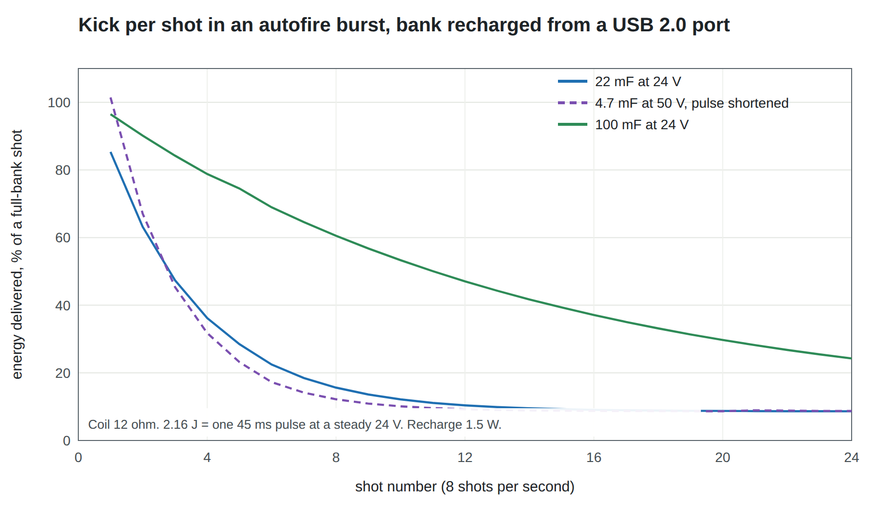
The chart is the central result of this dive. Bank voltage changes the bank’s size; bank capacitance changes burst depth; neither changes where the curve ends.
4.2 Energy in a Bank, and Why Voltage Matters
A capacitor charged to V holds ½CV². A bank can never be fully emptied into a coil, because the current falls as the voltage does; what matters is the energy released between the starting voltage V₁ and the lowest voltage still useful, V₂:
E = ½ C (V₁² − V₂²)
Because energy goes with the square of voltage, the same shot can be stored in a much smaller bank at a higher voltage. For one 2.16 J shot (the 24 V, 12 Ω coil of Vol 1 for 45 ms):
Table 1 — Because energy goes with the square of voltage, the same shot can be stored in a much smaller bank at a higher voltage. For one 2.16 J shot (the 24 V, 12 Ω coil of [Vol 1](/light-guns/power-and-connectivity/power-supplies/vol-1/) for 45 ms)
| Bank charged to | Allowed to fall to | Capacitance needed for one shot |
|---|---|---|
| 24 V | 20 V | 24.5 mF |
| 24 V | 22 V | 47.0 mF |
| 35 V | 24 V | 6.7 mF |
| 50 V | 30 V | 2.7 mF |
| 63 V | 40 V | 1.8 mF |
A 24 V bank that is allowed to fall only to 22 V, so that the kick barely changes, needs 47 mF for one shot. Charged to 50 V and allowed to fall to 30 V, the same energy fits in 2.7 mF: about a seventeenth of the capacitance. This is the reason the Sinden wiki describes its recoil capacitor as storing “a high voltage charge.”1 Sinden does not publish the voltage, and this dive does not guess it; the arithmetic shows why any USB-powered design is pushed upward.
The price of high voltage is that the coil sees it. A 24 V coil connected to a 50 V bank draws twice its rated current at the start of the pulse, four times its rated power, and must be switched off sooner to deliver the same energy. The firmware has to know that, and the driver, the flyback clamp and the bank’s capacitors all need ratings for the higher voltage.
4.3 What a Bank Does to the Pulse
A brick holds the coil voltage constant. A bank does not: during the pulse it discharges through the coil with time constant RC, and the current falls with it.
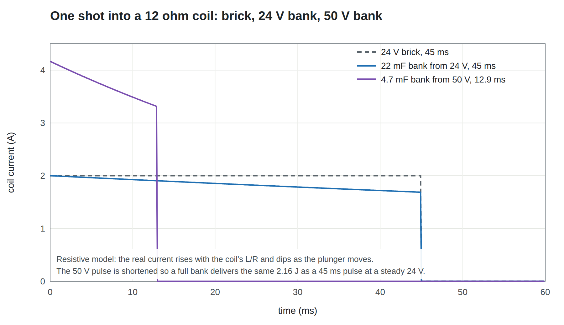
Two consequences for a design:
- The kick changes with the bank’s state of charge. A firmware that fires a fixed 45 ms pulse gives a strong kick from a full bank and a weak one from a depleted bank. A firmware that reads the bank voltage and stretches or shortens the pulse can hold the energy per shot constant down to some minimum voltage, then decide whether to fire weaker or not at all. This is the “fade gracefully” behaviour of Vol 3, and it needs only a resistor divider into an ADC pin.
- A short, high-current pulse is not the same kick as a long, low-current one of equal energy. Force on a solenoid plunger rises steeply with current, and the plunger takes time to travel its stroke; a pulse that ends before the plunger arrives wastes energy. Which shape gives the best kick for a given coil is a question for the Solenoid Recoil dive and for measurement. The supply’s job is to deliver whichever shape is chosen, consistently.
4.4 Sizing for a Burst
A burst-sizing procedure that needs only the numbers already in this dive:
- Energy per shot, E. V²/R × pulse length for a fixed pulse; or the target energy if the firmware regulates it. Measure it later (Vol 6).
- Usable voltage window, V₁ to V₂. V₁ is the charger’s set point; V₂ is the lowest voltage at which the kick is still acceptable, or the lowest the firmware will fire from.
- Source power into the bank, P. The source’s grant, minus the electronics, times the charger’s efficiency. For a brick behind a limiter, the limiter’s current times the bank voltage.
- Burst length, N shots at rate f. During the burst the bank loses N·E and gains P·N/f. The bank must hold the difference within its window:
½ C (V₁² − V₂²) ≥ N·E − P·N/f
- Recovery time. After the burst, the time to return to V₁ is the energy deficit divided by P.
A worked example for architecture C on a USB 2.0 port: a 24 V, 12 Ω coil, E = 2.16 J, P = 1.49 W, and a six-shot full-strength burst at 8 shots/s with the bank allowed to fall from 50 V to 30 V. The bank must supply 6 × 2.16 − 1.49 × 6/8 = 11.8 J, so C ≥ 2 × 11.8 / (50² − 30²) = 14.8 mF. Fourteen point eight millifarads at 63 V is a large can; recovery takes 11.8 / 1.49 = 8 s. On a 3 A Type-C port, P = 12.1 W, the same burst needs only 3.9 J from the bank (4.9 mF) and recovers in 0.3 s.
The example shows the trade plainly. USB 2.0 can give a convincing six-shot burst, but only from a capacitor the size of a small drink can, and then it needs eight seconds of quiet.
4.5 Charge-Current Limiting: Making the Bank Do the Work
The most common mistake with bulk capacitance is to hang it directly across a brick that is tripping on the solenoid pulse, expecting it to help. It does very little. A regulated brick is a stiff voltage source; when the coil draws 4 A, the brick supplies almost all of it, because the capacitor would only discharge if the voltage fell, and the brick’s regulator is working precisely to stop the voltage falling. The brick still sees the pulse, and still trips.
For a bank to carry the pulse, something must stop the source from supplying it. That is a limiter between source and bank: the source charges the bank at a controlled current, and the bank, not the source, feeds the coil.
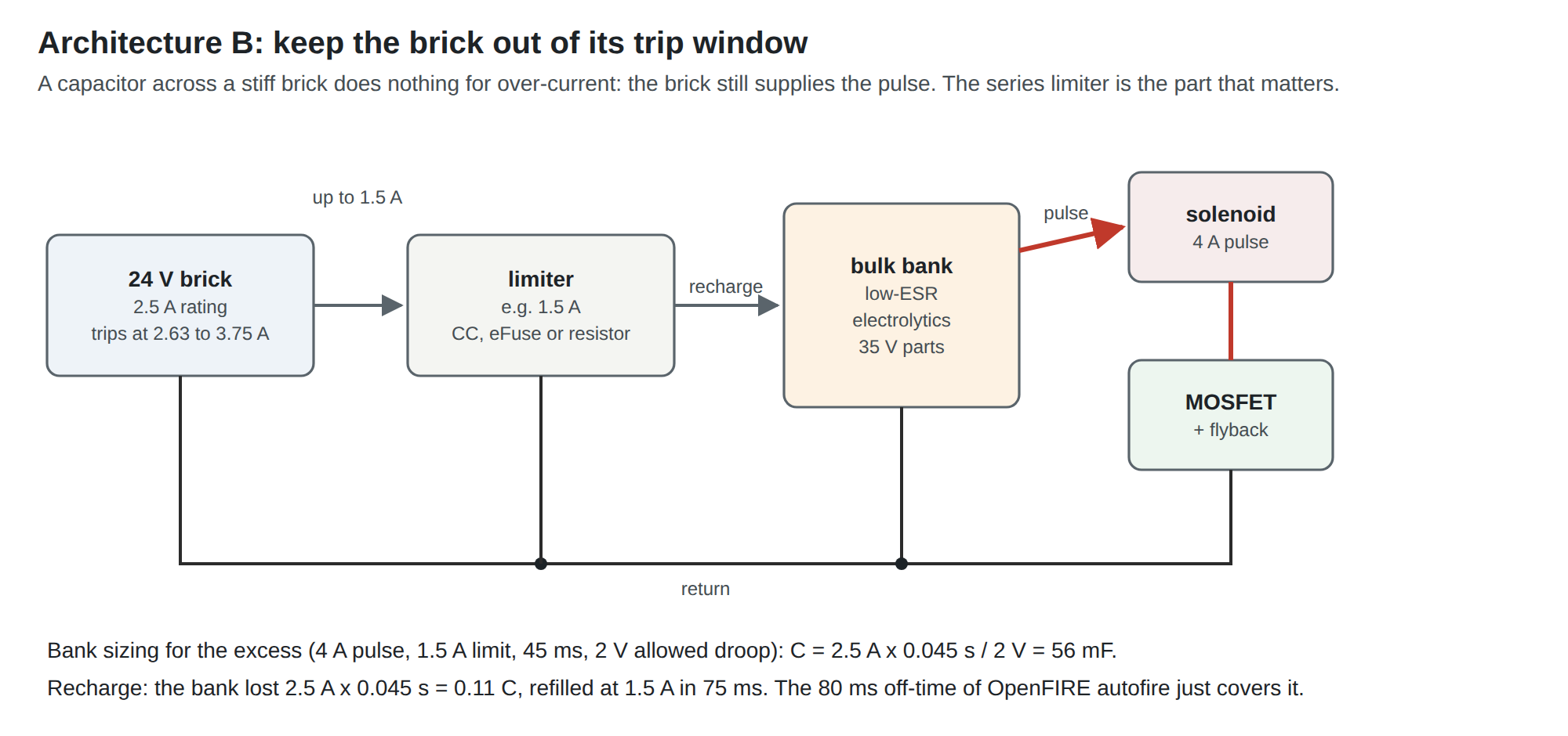
Three ways to build the limiter, in order of sophistication:
Table 2 — Three ways to build the limiter, in order of sophistication
| Limiter | How it limits | Advantage | Drawback |
|---|---|---|---|
| Series resistor | I = (V_source − V_bank) / R | Trivial; no failure modes worth naming | Current depends on droop; recharge is exponential with τ = RC; dissipates during recharge |
| eFuse or current-limited switch | Constant current at a set limit | Flat recharge current; also protects against a shorted bank | Dissipates (V_source − V_bank) × I while limiting; needs a part rated for the voltage |
| Constant-current charger (buck or boost) | Switch-mode, regulated current | Efficient; sets voltage and current independently | Most complex |
For architecture B with a stiff brick, a resistor is usually enough. In the example above, with the bank allowed to fall 2 V below 24 V, a series resistor of 2 V / 1.5 A ≈ 1.3 Ω limits the brick to 1.5 A at the worst point of droop and recharges the 56 mF bank with τ = 1.3 Ω × 56 mF ≈ 75 ms. The resistor carries pulses, not continuous current, and should be chosen for its pulse rating. The brick never sees more than 1.5 A, comfortably below the bottom of its trip band, and the coil gets its 4 A from the bank.
Two rules keep architecture B safe. The bank and every part on it must be rated for the source’s over-voltage protection point, not its nominal voltage: the GST60A24’s over-voltage protection is specified at 25.2 to 32.4 V, so a 35 V bank is the minimum.2 And the bank must not be connected to the brick’s output connector in a way a user can short; a few millifarads at 24 V will arc a barrel plug.
4.6 Choosing Electrolytics
The bank for architectures B and C is aluminium electrolytic capacitors. What to look for, in roughly this order:
- Voltage rating above the highest voltage the bank can ever reach: the source’s over-voltage trip for architecture B, the boost converter’s over-voltage protection (not its set point) for architecture C. A margin above that is good practice; electrolytics are not tolerant of over-voltage.
- Ripple current rating. Each shot discharges the bank in tens of milliseconds and each recharge refills it. The RMS of that current heats the capacitor through its ESR. Compute the RMS current of the worst firing pattern and compare it with the maker’s ripple rating at the relevant frequency and temperature. Low-ESR, high-ripple series exist for exactly this job.
- ESR. A few tens of milliohms is typical of large cans. At 4 A it costs a fraction of a volt, small compared with the cable drop of Vol 2, but it is lost on every shot.
- Size. Large-value, high-voltage cans are large. In an MP7-sized shell the bank competes with the solenoid, the camera and the board for space. Several smaller cans in parallel can fit irregular cavities and share the ripple current.
- Temperature. Electrolytic life halves for roughly every 10 °C rise; a bank mounted against a hot solenoid ages fast. Keep them apart.
The specific parts belong in the BOM of the Reference Electronics dive, chosen from the maker’s ripple-current tables once the coil and firing pattern are fixed.
4.7 Supercapacitors
A supercapacitor (electric double-layer capacitor) stores far more charge than an electrolytic of the same size but at a much lower voltage: a single cell is rated about 2.7 V. Eaton’s HV series is typical:3
Table 3 — Supercapacitors
| Part | Capacitance | Max initial ESR | Pulse current (1 s) | Continuous current | Size (D × L) |
|---|---|---|---|---|---|
| HV1030-2R7106-R | 10 F | 34 mΩ | 10 A | 3.3 A | 10 × 31.5 mm |
| HV1625-2R7256-R | 25 F | 27 mΩ | 20 A | 3.4 A | 16 × 28.4 mm |
| HV1860-2R7107-R | 100 F | 12 mΩ | 61 A | 11 A | 18 × 60.5 mm |
All are rated 2.7 V with a 3.0 V surge rating and a capacitance tolerance of −10 % to +30 %; Eaton’s life rating is 1,000 hours at 65 °C and 2.7 V, after which capacitance may have fallen by up to 30 % and ESR doubled, and cycle life is 500,000 cycles under the same end-of-life criteria.3
Eaton also makes two-cell packs. The PHB-5R0V505-R is a 5.0 F pack rated 5.0 V (5.5 V surge), with a maximum ESR of 0.12 Ω at 1 kHz, 10.5 × 20.8 × 32 mm.4 Its ESR is roughly double that of two discrete HV cells of similar capacitance, and its datasheet says nothing about internal balancing.
A two-cell stack of HV1625 cells is 12.5 F at up to 5.4 V, 54 mΩ. Discharged from 5.0 V to 3.0 V it releases 100 J: about 39 shots of 2.16 J after an 85 % efficient boost, or about 157 shots of the 12 V coil’s 0.54 J. That is a very deep burst in a package two 16 mm cells in size.
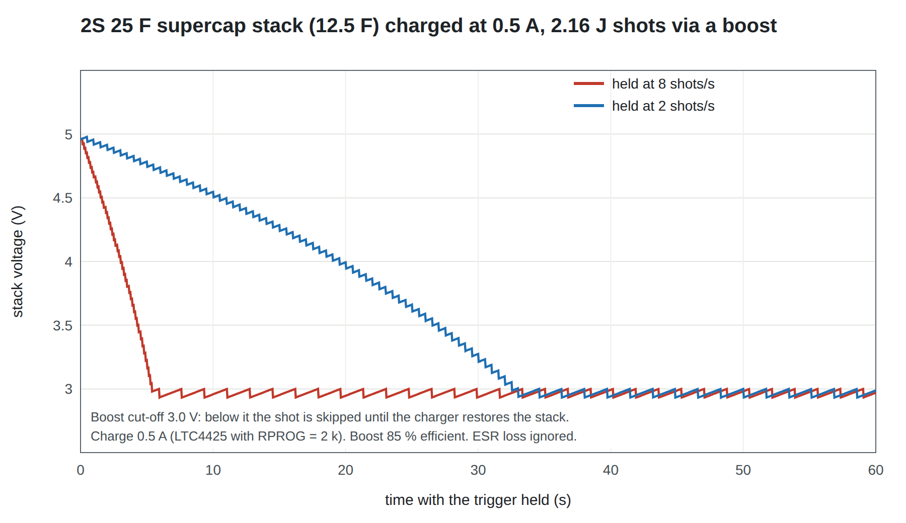
The chart repeats the lesson of the electrolytic bank at larger scale: the stack sets the burst, the charger sets the floor.
Charging a stack from USB is a solved problem. Analog Devices’ LTC4425 is a linear charger for exactly this: it “charge[s] a 2-cell supercap stack from either a Li-Ion/Polymer battery, a USB port, or a 2.7V to 5.5V current-limited supply,” with a programmable current limit, a built-in cell balancer, and selectable 2.45 V or 2.7 V per-cell clamps (4.9 V or 5.4 V for the stack).5 The charge current is set by a single resistor: 2 A with 0.5 kΩ, 0.2 A with 5 kΩ, so about 2 kΩ gives the 0.5 A a USB 2.0 port allows. Its “smart charge current profile” cuts the current to a tenth while the stack is more than 750 mV below the input, limiting inrush, and its 50 mΩ ideal-diode path lets the stack feed loads directly.5
Charging takes time. At 0.5 A, a fully discharged 12.5 F stack takes about two minutes to reach 5 V, and a stack emptied to 3 V takes nearly a minute to refill. A gun built around a supercap will not have full recoil for the first minutes after it is plugged in, and the firmware should know it.
4.8 Balancing a Series Stack
Two supercap cells in series share a charge, not a voltage. Each takes a voltage inversely proportional to its capacitance. With Eaton’s −10 % to +30 % tolerance, the worst pair is one cell at 0.9 × 25 = 22.5 F and one at 1.3 × 25 = 32.5 F. Charged to 5.4 V together, the smaller cell takes 5.4 × 32.5 / 55 = 3.19 V, above its 3.0 V surge rating, let alone its 2.7 V working rating, while the larger takes 2.21 V. Leakage current differences then push the imbalance further over time.
A stack of two cells therefore needs balancing, and there are three common ways to do it:
- Passive resistors across each cell. Simple, but they draw current permanently and only correct imbalance slowly.
- Active shunt clamps that conduct only when a cell exceeds its limit. This is what the LTC4425 includes internally, with shunt currents of about 140 to 160 mA at its datasheet test condition.5
- A lower stack voltage. Charging the pair to 4.9 V (2.45 V per cell nominal) rather than 5.4 V gives margin for capacitance mismatch at the cost of about a quarter of the energy usable above 3 V. The LTC4425’s pin-selectable 2.45 V clamp exists for this reason.
Eaton’s PHB two-cell pack does not state whether it includes balancing, so treat it as unbalanced.4
4.9 Getting the Energy Out: The Boost Problem
A supercap stack at 3 to 5 V cannot drive a 24 V coil directly. It needs a boost converter between stack and coil, and that converter must supply the pulse, not a trickle. For the 48 W pulse of the 24 V, 12 Ω coil at 85 % efficiency, the boost draws 11.3 A from the stack at 5 V and 18.8 A at 3 V. That is a substantial converter: a boost controller with external MOSFETs and an inductor rated for 20 A peak, not a module. At 15 A, the stack’s own 54 mΩ costs 0.8 V and 12 W, which is why the low-ESR cells above are preferred to the pack.
The alternative is to change the coil. A solenoid wound for 5 V with a resistance around half an ohm draws about 10 A from the stack directly and dissipates the same 48 W as the 24 V coil; the force depends on ampere-turns, not voltage, so a coil with fewer turns of heavier wire at higher current can produce the same kick. Such coils are not common light-gun parts; whether one can be bought or must be wound is a question for the Solenoid Recoil dive. If one can be had, architecture D loses its hardest block.
This is why architecture D is listed last in Vol 1. The supercap is easy; the high-current boost is not. It becomes much more attractive in a battery-powered gun, where the LiPo can supply the boost directly and the supercap is unnecessary, which is the LiPo Batteries dive’s subject.
4.10 Stored Energy and Safety
The banks in this volume are modest by the standards of a photoflash or a coilgun, but they are not trivial:
Table 4 — The banks in this volume are modest by the standards of a photoflash or a coilgun, but they are not trivial
| Bank | Stored at full charge |
|---|---|
| 22 mF at 24 V | 6.3 J |
| 56 mF at 24 V (architecture B example) | 16 J |
| 14.8 mF at 50 V (burst example) | 18.5 J |
| 12.5 F at 5.4 V (2S 25 F stack) | 182 J |
The hazards are of three kinds.
Short circuits. A bank shorted by a dropped screwdriver or a misplaced probe dumps its energy in a spark that can weld tool tips and burn fingers. Eaton gives a short-circuit current of 100 A for its 25 F cell, “for safety information only.”3 A supercap stack can deliver tens of amps through a fault for seconds; a fuse between the stack and everything else is good practice.
Voltage. Banks at 24 V present no shock hazard. A bank charged to 50 V or 63 V is still below the 60 V DC threshold that product-safety standards commonly use for the boundary of safe-to-touch circuits, but the margin is small; the exact limits should be checked in IEC 62368-1 before a design is fixed. Banks above that level are outside what a light gun needs.
Charge that remains after unplugging. A bank holds its charge long after the cable is removed. Add a bleeder resistor across every bank, sized so the bank falls below a safe level within a stated time (τ = RC; three time constants takes it to about 5 %), and accept the small continuous loss. Before working inside the gun, check the bank with a meter. Supercaps should be shorted through a resistor for storage and shipping, which is also what makes them legal to ship.
Polarity matters for both technologies. A reversed electrolytic can vent; a reversed supercap is damaged. Polarised connectors (the XT30 of Vol 2) and keyed footprints remove the possibility.
4.11 Why This, and Why Not the Others
The storage choice depends on the architecture, so it is made per architecture. The criteria: energy per litre at the voltage the coil needs; whether the stored energy can reach the coil without another converter; balancing and inrush; behaviour on a short; and whether the part has a maker’s datasheet with a ripple or pulse rating.
A regulated rail changes the sizing. The Solenoid Recoil dive’s rail, now decided (D13, D14), regulates the coil current and ends the pulse at landing. Two numbers in this volume move as a result. Energy per shot falls: the sibling dive’s model draws about 0.65 J from 24 V for a pulse ended 2 ms after landing, against 2.16 J for the fixed 45 ms pulse used above. And the usable window widens: under regulation the kick does not change as the bank droops, as long as the rail stays above about 1.5 times the coil’s hot I·R, which for a coil chosen at half the rail is about 18 V. One shot from 24 V down to 18 V then needs 2 × 0.65 / (24² − 18²) ≈ 5.2 mF, against 47 mF for one fixed-voltage shot allowed to fall only to 22 V. The bank becomes a can, not a drink can. These figures come from a model, not a measurement; T1 and T7 of Vol 6 replace them.
Table 5 — Why This, and Why Not the Others
| Architecture | Pick | Status | Why | Why not the others |
|---|---|---|---|---|
| A, brick direct (Stages 1 and 2) | Local reservoir only: the Reference Electronics board’s 1000 µF polymer at the input plus 1 µF per stage | Proposed | Supplies the edges and the regulator’s chopping current locally; the brick, sized below its trip band (Vol 2), supplies the pulse | A bulk bank across a stiff brick does not stop a trip (section 4.5) and adds a plug-in spark and inrush for nothing; a supercap stack is the wrong voltage |
| B, brick through a limiter | Aluminium electrolytic bank at the rail voltage, low-ESR, high-ripple series, behind a series resistor | Proposed for any gun whose pulse exceeds its brick | Stores the pulse at the coil’s own voltage, so no converter sits between bank and coil; no balancing; a resistor limiter has no failure mode worth naming | Supercaps need a 20 A boost out (section 4.9) and balancing; polymer capacitors are the reservoir part at the board; bank-sized polymer values and prices were not checked for this dive, so they are not recommended here |
| C, USB only | Electrolytic bank charged above the rail (35–50 V class) through a current-limited boost | Deferred to the Fully Wired dive | E ∝ V²: the bank shrinks by an order of magnitude at 50 V (section 4.2) | A supercap at 5 V holds more energy but cannot reach a 24 V coil without the boost of section 4.9 |
| D, USB to a supercap stack | 2S supercap, LTC4425-charged, only if a low-voltage coil is found | Rejected for now | Deepest burst per volume, and USB charging and balancing are solved in one chip | The high-current boost out is the hardest block in the dive, and the 182 J short-circuit energy is the largest |
| Battery builds | LiPo, no bank | Deferred | A pack is a better store than any capacitor here | Its own dive: LiPo Batteries |
The voltage rating of any capacitor on the rail is set by the source’s over-voltage protection, not the nominal rail. The 24 V GST60A shuts down somewhere between 25.2 and 32.4 V,2 so a 35 V part is above it. The NSP-75-24, once the two-stage option, shuts down between 28 and 36 V,6 which a 35 V part is not above; with the stages sequenced (decision D16) the GST60A24 class is the brick (Vol 2, section 2.11) and the NSP case falls away. Any source whose band reaches past 35 V would still need 50 V parts. The Reference Electronics board’s 35 V polymer is right for the GST.
Footnotes
-
Sinden Lightgun wiki, “Recoil Issues,” last edited 29 December 2022, Internet Archive capture of 6 March 2026. https://web.archive.org/web/20260306211156/https://www.sindenwiki.org/wiki/Recoil_Issues ↩ ↩2
-
Mean Well, GST60A series specification, file GST60A-SPEC 2026-04-03 (over-voltage protection 25.2 to 32.4 V on the 24 V model). https://www.meanwell.com/Upload/PDF/GST60A/GST60A-SPEC.PDF (downloaded 2026-10-18). ↩ ↩2
-
Eaton, HV supercapacitors, cylindrical cells data sheet, effective January 2020 (specification and performance tables, short-circuit current note). https://www.eaton.com/content/dam/eaton/products/electronic-components/resources/data-sheet/eaton-hv-supercapacitors-cylindrical-cells-data-sheet.pdf (downloaded 2026-10-18). ↩ ↩2 ↩3
-
Eaton, PHB supercapacitors, cylindrical pack data sheet, effective June 2017. https://www.eaton.com/content/dam/eaton/products/electronic-components/resources/data-sheet/eaton-phb-supercapacitors-cylindrical-pack-data-sheet.pdf (downloaded 2026-10-18). ↩ ↩2
-
Analog Devices (Linear Technology), LTC4425 Linear SuperCap Charger with Current-Limited Ideal Diode and V/I Monitor, data sheet 4425fa, LT 0216 Rev A (features, description, electrical characteristics ICHG and shunt current). https://www.analog.com/media/en/technical-documentation/data-sheets/4425fa.pdf (downloaded 2026-10-18). ↩ ↩2 ↩3
-
Mean Well, NSP-75 series specification, file NSP-75-SPEC 2026-03-13 (over-voltage protection 28 to 36 V on the 24 V model). https://www.meanwell.com/Upload/PDF/NSP-75/NSP-75-SPEC.PDF (downloaded 2026-10-18). ↩
Comments (0)